Note: Descriptions are shown in the official language in which they were submitted.
CA 03031843 2019-01-24
1
PALLET HAVING PANELS AND TUBE SEGMENTS
The invention relates to a pallet, in particular for the transport of goods.
Transport pallets according to EN 13698-1 and UIC 435-2 (Europool pallets) are
known
from the prior art. These comprise three floor boards, each connected by three
blocks to
three transverse boards on which five cover boards are arranged. The
corresponding
boards are formed of solid wood.
A disadvantage of solid wood pallets is their relatively high weight (20 to 24
kg, depending
on wood moisture content, with dimensions of 1200 x 800 x 144 mm).
This results in the objective of providing a pallet which, compared to the
state of the art,
has a reduced weight with the same stability.
This objective is attained by the pallet of the present invention according to
claim 1, the
foot of the present invention according to claim 15, the runner of the present
invention
according to claim 17, the sandwich block of the present invention according
to claim 18
and the method of the present invention according to claim 23. Specific
embodiments of
the pallet are specified in dependent claims 2 to 14, a specific embodiment of
the foot is
specified in dependent claim 16, specific embodiments of the sandwich block
are specified
in claims 19 to 22 and specific embodiments of the method are specified in
claims 24 and
25. The embodiments are described hereafter.
A first aspect of the invention relates to a pallet, comprising a basic body
that comprises
at least the following components:
- a first panel and a second panel arranged parallel to the first panel, the
first panel and
the second panel each extending in the direction of a pallet width and a
pallet depth, the
pallet comprising a pallet height perpendicular to the pallet width and the
pallet depth,
- a layer arranged between the first panel and the second panel, the layer
comprising a
plurality of tube segments, the tube segments each comprising two cut ends
which delimit
the tube segments in the circumferential direction, the tube segments each
comprising a
CA 03031843 2019-01-24
2
segment depth, a segment width and a segment height, wherein the segment depth
corresponds to the maximum extension of the tube segment in the longitudinal
extension
direction, and wherein the segment width corresponds to the maximum extension
of the
tube segment along an (imaginary) connecting line between the cut ends
perpendicularly
to the longitudinal extension direction (that is in the cross-sectional
direction of the tube
segment), and wherein the segment height corresponds to the maximum extension
perpendicular to the segment depth and the segment width, and wherein the tube
segments are arranged in the layer such that the segment depth runs in the
direction of
the pallet height, the segment width runs in the direction of the pallet width
and the
segment height runs in the direction of the pallet depth, wherein the layer
comprises at
least one cutout which is continuous in the direction of the pallet height,
and wherein the
first panel comprises at least one first opening which at least partially
overlaps with the at
least one cutout.
.. This means in particular that the at least one first opening has the same
dimensions as
the at least one cutout, wherein the at least one first opening is coincident
with the at least
one cutout, or that the at least one first opening is smaller than the at
least one cutout,
part of the at least one cutout being coincident with the at least one first
opening.
.. A first sub-aspect of the first aspect of the invention relates to a pallet
comprising a basic
body which comprises at least the following components:
- a first panel and a second panel arranged parallel to the first panel, the
first panel and
the second panel each extending in the direction of a pallet width and a
pallet depth, the
pallet comprising a pallet height perpendicular to the pallet width and the
pallet depth,
.. - a layer arranged between the first panel and the second panel, the layer
comprising a
plurality of tube segments, the tube segments each comprising two cut ends
which delimit
the tube segments in the circumferential direction, and wherein each of the
tube segments
comprises a segment depth, a segment width and a segment height, wherein the
segment
depth corresponds to the maximum extension of the tube segment in the
longitudinal
.. extension direction, and wherein the segment width corresponds to the
maximum
extension of the tube segment along an (imaginary) connecting line between the
cut ends
perpendicularly to the direction of longitudinal extension (that is in the
cross-sectional
CA 03031843 2019-01-24
3
direction of the tube segment), and wherein the segment height corresponds to
the
maximum extension perpendicular to the segment depth and the segment width,
and
wherein the tube segments are arranged in the layer such that the segment
depth runs in
the direction of the pallet height, the segment width runs in the direction of
the pallet width
and the segment height runs in the direction of the pallet depth, wherein the
layer
comprises at least one cutout which is continuous in the direction of the
pallet height,
wherein the at least one cutout comprises an extension in the direction of the
pallet width
which corresponds at least to the segment width and an extension in the
direction of the
pallet depth which corresponds at least to the segment height, and wherein the
first panel
comprises at least one first opening which at least partially overlaps with
the at least one
cutout.
A second sub-aspect of the first aspect of the invention relates to a pallet
comprising a
basic body comprising at least the following components:
- a first panel and a second panel arranged parallel to the first panel, the
first panel and
the second panel each extending in the direction of a pallet width and a
pallet depth, the
pallet comprising a pallet height perpendicular to the pallet width and the
pallet depth,
- a layer arranged between the first panel and the second panel, the layer
comprising a
plurality of tube segments, the tube segments each comprising two cut ends
which delimit
the tube segments in the circumferential direction, wherein each of the tube
segments
comprises a segment depth, a segment width and a segment height, wherein the
segment
depth corresponds to the maximum extension of the tube segment in the
longitudinal
extension direction, and wherein the segment width corresponds to the maximum
extension of the tube segment along an (imaginary) connecting line between the
cut ends
perpendicularly to the direction of longitudinal extension (that is in the
cross-sectional
direction of the tube segment), and wherein the segment height corresponds to
the
maximum extension perpendicular to the segment depth and the segment width,
and
wherein the tube segments are arranged in the layer such that the segment
depth runs in
the direction of the pallet height, the segment width runs in the direction of
the pallet width
and the segment height runs in the direction of the pallet depth, wherein the
layer
comprises at least one cutout which is continuous in the direction of the
pallet height, the
at least one cutout comprising an extension in the direction of the pallet
width which is less
CA 03031843 2019-01-24
4
than the segment width and an extension in the direction of the pallet depth
which is less
than the segment height, and wherein the first panel comprises at least one
first opening
which at least partially overlaps with the at least one cutout.
The pallet according to the invention is characterized by a very low weight
and high
mechanical stability, in particular due to the wood composite used and the
cavities in the
layer. Furthermore, additional components, e.g. the feet of a pallet, can be
advantageously
inserted into the cutouts.
In the context of this invention, the term tube segment refers to a part of a
real or imaginary
tube with a longitudinal direction of extension. The cross-section of the tube
perpendicular
to its longitudinal extension direction comprises a circumference, i.e. an
imaginary line,
which delimits the cross-section on its outside. The cross-section is not
necessarily
circular, but can also be angular or elliptical. The circumferential direction
of the tube runs
(also in the case of a tube with an angular cross-section) along an imaginary
circle, which
defines the cross section of the tube perpendicularly to the longitudinal
direction of
extension.
The tube segments each comprise a wall which is delimited in the
circumferential direction
by the cut ends, wherein the wall is open in the circumferential direction.
Therein, the wall
is continuously open in longitudinal extension direction. The circumferential
direction of
the tube segment means the circumferential direction of the associated real or
imaginary
tube which has a closed wall. The tube segment can be particularly formed by
cutting of
a tube, but can also be formed in other ways, in particular by mechanically
connecting
several strips or by an extruder process.
The cut ends of the tube segment delimit the tube segment in the
circumferential direction.
The wall of the tube segment is thus delimited in the circumferential
direction by the cut
ends. The cross-section of the tube segment is thus formed by an open profile.
In
particular, the open profile can be circular segment shaped, e.g.
semicircular, U-shaped
or V-shaped.
CA 03031843 2019-01-24
The tube segments further comprise two cut surfaces, which delimit the tube
segments in
the longitudinal extension direction. In particular, the cut surfaces run
perpendicular to the
longitudinal extension direction.
5 According to an embodiment, the tube segments are each connected to the
first panel by
one of the cut surfaces and/or mechanically connected to the second panel by
the
respective other cut surface.
According to a further embodiment, the tube segments are perpendicular to the
first panel
and the second panel with regard to their longitudinal extension direction.
In particular, the connecting line between the cut ends runs along the common
direction
of the cut ends, in particular in cross section with respect to the
longitudinal extension
direction of the tube segment. In cases where the cut ends are not parallel to
each other
in cross-section, the connecting line is defined between the points of the cut
surfaces with
the largest extension in circumferential direction.
The tube segments each form a cavity which is delimited by the inner surface
of the wall.
Therein, the segment width (i.e. the outer width of the tube segment)
corresponds to the
sum of the maximum extension of the cavity in the direction of the connecting
line between
the cut ends perpendicular to the longitudinal extension direction (i.e. in
cross-section)
and twice the wall thickness. The segment height corresponds to the sum of the
maximum
extension of the cavity perpendicular to the segment width and the wall
thickness.
In the context of this invention, the term 'cutout' can therefore refer either
to the said cavity
formed by the interior of the tube segments or to a gap between two adjacent
tube
segments of the layer. The extension of the cavity inside the tube segments
is, as
described above, twice as much as the wall thickness smaller than the segment
width and
smaller by one wall thickness than the segment height and is therefore a
cutout in the
sense of the invention.
CA 03031843 2019-01-24
6
The at least one cutout comprises an extension in the direction of the pallet
width and an
extension in the direction of the pallet depth. In the event that the at least
one cutout has
a shape in which the extension in the direction of the pallet width or the
pallet depth is not
constant, the term 'extension of the cutout' refers to the minimum extension
in the
respective direction in the context of the present invention.
According to an embodiment of the pallet, the at least one cutout comprises an
extension
at least equal to the segment width in the direction of the pallet width, and
the at least one
cutout comprises an extension at least equal to the segment height in the
direction of the
pallet depth.
In this case, the corresponding cavities inside the tube segments are smaller
in both
directions (in the direction of the pallet width and in the direction of the
pallet depth) than
the cutout. Herein, a cutout is formed in particular by omitting tube segments
at certain
positions of the layer.
According to a further embodiment, the at least one cutout comprises an
extension which
is smaller than the segment width in the direction of the pallet width, and
the at least one
cutout comprises an extension that is less than the segment height in the
direction of the
pallet depth.
In this case, the cavities inside the tube segments in particular also form
cutouts in the
sense of the invention, into which e.g. a foot of the pallet can be inserted.
According to a further embodiment, the at least one cutout comprises an
extension which
corresponds to at least twice the segment width in the direction of the pallet
width.
According to a further embodiment, the at least one cutout comprises an
extension which
corresponds to at least twice the segment height in the direction of the
pallet depth.
CA 03031843 2019-01-24
7
According to a further embodiment, the extension of the cutout in the
direction of the pallet
width is at least 50 mm, wherein the extension in the direction of the pallet
depth is at least
30 mm.
The cutout is therefore sufficiently large for the insertion of a foot.
The at least one first opening of the first panel comprises an extension in
the direction of
the pallet width and an extension in the direction of the pallet depth.
According to an
embodiment, the at least one first opening has a rectangular shape. In the
event that the
at least one first opening has a shape in which the extension in the direction
of the pallet
width or the pallet depth is not constant, the minimum extension in the
respective direction
is meant with the term 'extension of the first opening' in the context of the
present
invention.
According to an embodiment, the pallet comprises a wood composite or is formed
of a
wood composite. According to an embodiment, the tube segments comprise a wood
composite or are formed of a wood composite. According to a further
embodiment, the
first panel and/or the second panel comprises a wood composite. According to a
further
embodiment, the first panel and/or the second panel is formed of a wood
composite.
In the context of the present invention, the term wood composite refers to a
material which
comprises comminuted wood, in particular wood chips, wood veneers, wood veneer
strips,
wood wool, wood fibres or wood dusts, or other lignocellulosic materials.
Furthermore, the
wood composite may in particular contain binders, adhesives and/or additives.
Additives
can in particular be hydrophobizing agents, wood preservatives, flame
retardants,
hardeners or paint particles. Binders include in particular urea glue,
synthetic resins, e.g.
phenolic resins, isocyanates, plastics and/or bioplastics. Wood veneers and/or
wood
veneer strips are used in particular for the production of plywood and/or
coarse particle
boards (OSB boards).
Wood composites include in particular solid wood composite, e.g. solid wood
panels (in
accordance with DIN EN 12775) or laminated wood panels, cross laminated
timber, glued
CA 03031843 2019-01-24
8
laminated timber, plywood and/or laminated timber, veneer wood composites,
e.g. veneer
plywood (FU), veneer laminated timber, veneer strip wood, bending plywood,
wood chip
materials, e.g. flat pressed boards (P2), extruded boards, chipboard
mouldings, coarse
chipboard (OSB boards, according to DIN EN 300) and/or chipboard strip (LSL),
wood
fibre materials, e.g. wood fibre insulation boards (HFD), porous fibre boards,
soft boards
(SB), medium hard fibreboards (MB), hard fibreboards (HB or HFH), hard
fibreboards,
extra hard fibreboards (HFE), medium density fibreboards (MDF), high density
fibreboards
(HDF) and/or ultra light fibreboards (ULDF), arboform or liquid wood.
The term fibreboard refers to the wood composites specified in DIN EN 622. The
term
chipboard refers to the wood composites specified in the standards DIN EN 309
and DIN
EN 312. The term plywood refers to the wood composites specified in the
standards DIN
68708 and DIN EN 313.
As a basic material for shell construction and interior construction, wood
composites have
the advantage of high material strength and mechanical load-bearing capacity
while being
lightweight at the same time.
According to an embodiment, the wood composite has a lignin content of >5%, in
particular
>10% by weight. This means that in particular paper and cardboard do not
represent wood
composites in the sense of the present invention, since the lignin of the wood
raw materials
used is largely removed during paper production, e.g. by chemical bleaching
agents.
According to a further embodiment, the wood composite is free of chemical
bleaching
agents.
According to a further embodiment, the wood composite is produced in a drying
process
at a wood moisture of < 20 %. Therein, the percentage refers to the ratio of
the water
weight to the absolutely dry wood mass. In a drying process, the wood
particles are dried
before fleece formation and pressing to yield the product and the product
comprises a
wood moisture of under 20%. Glue can be applied before or after drying.
CA 03031843 2019-01-24
9
According to a further embodiment, the wood composite comprises wood fibres
pressed
under pressure and/or heat. According to a further embodiment, the wood
composite
comprises a density of > 800 kg/m3. High-density fibreboards, for example,
have a density
in this range.
According to a further embodiment, the tube segments are formed of a material
of a high
density fibreboard (HDF). High density fibreboard (HDF) has a particularly
high strength.
According to a further embodiment, the tube segments are formed from a
plurality of strips.
The strips run in the longitudinal extension direction of the tube segment. In
this
embodiment, in particular a tube segment with an angular cross-section is
formed.
According to an embodiment, the strips comprise a wood composite or are formed
of a
wood composite.
According to an embodiment, the tube segments are formed of pressed wood, in
particular
pressed wood fibres or wood chips. For example, the tube segments can be
produced by
cutting tubes from pressed wood. The production of such a tube can, for
example, be
carried out by pressing a wood mass comprising shredded wood, in particular
wood fibres
or wood shavings, into a press forming channel with a tubular cutout and
hardening of the
wood mass. Alternatively, a half tube or tube segment can also be produced
directly by
pressing a wood mass, in particular in a press forming channel with a tube
segment
shaped cutout or by a flat pressing tool with a suitable contour.
According to a further embodiment, the wood composite is produced from a wood
mass,
in particular a dendro mass, by means of an extruder process.
The use of pressed wood allows the cost-effective production of tubes or tube
segments
of almost any shape and dimension, whereby a very uniform dimensioning of the
tubes or
tube segments can be achieved in comparison to natural products.
CA 03031843 2019-01-24
According to a further embodiment, the tube segments comprise an angular cross-
section,
in particular an octagon segment shaped cross-section.
Tube segments with an octagon segment cross-section achieve a particularly
5 advantageous distribution of forces when exerting forces on the basic
body of the pallet
according to the invention, which results in increased mechanical stability of
the pallet.
According to a further embodiment, the tube segments comprise a U-shaped cross-
section. According to a further embodiment, the tube segments comprise a
trapezoidal
10 cross-section.
A trapezoidal cross section has the advantage of being particularly easy to
manufacture
and at the same time has good stability properties.
According to a further embodiment, the tube segments are formed of a plate, in
particular
an HDF plate, which is folded into a U-shape or a trapezoidal segment shape.
Therein, the tube segments are formed in particular by milling out V-shaped
mitres in the
plate, folding the plate at the mitres and gluing at the mitres.
According to a further embodiment, all tube segments of the layer essentially
comprise a
uniform segment depth.
According to a further embodiment, all tube segments of the layer essentially
comprise a
uniform segment width.
According to a further embodiment, all tube segments of the layer essentially
comprise a
uniform segment height.
According to a further embodiment, the at least one cutout is completely
surrounded by
tube segments in the direction of the pallet width and pallet depth.
CA 03031843 2019-01-24
11
According to a further embodiment, the layer comprises at least one row of
tube segments
extending in the direction of the pallet width, wherein particularly adjacent
tube segments
within the at least one row are mechanically connected.
The mechanical stability of the pallet is advantageously increased by a
mechanical
connection of adjacent tube segments.
According to a further embodiment, the layer comprises at least one first row
of tube
segments extending in the direction of the pallet width and at least one
second row of tube
segments extending in the direction of the pallet width.
According to a further embodiment, the layer comprises at least one first row
of tube
segments extending in the direction of the pallet width, at least one second
row of tube
segments extending in the direction of the pallet width and at least one
strip, wherein the
.. tube segments of the at least one first row and the tube segments of the at
least one
second row are mechanically connected via the at least one strip, wherein
particularly the
tube segments of the at least one first row are mechanically connected to a
first strip side
of the at least one strip by means of their cut ends, and the tube segments of
the at least
one second row are mechanically connected by means of their cut ends to a
second strip
side of the at least one strip opposite the first strip side.
Such strips mechanically connect and stabilize the tube segments of two rows,
thus
increasing the mechanical stability of the basic body of the pallet.
According to a further embodiment, the second panel comprises at least one
second
opening which at least partially overlaps with the at least one cutout.
This means in particular that the at least one second opening comprises the
same
dimensions as the at least one cutout, the at least one second opening being
coincident
with the at least one cutout, or that the at least one second opening is
smaller than the at
least one cutout, part of the at least one cutout being coincident with the at
least one
second opening.
CA 03031843 2019-01-24
12
According to a further embodiment, the second panel has at least one second
opening
which at least partially overlaps with the at least one cutout, wherein the at
least one
second opening comprises a smaller extension in the direction of the pallet
depth or in the
direction of the pallet width, in particular in the direction of the pallet
depth, than the at
least one first cutout with which the at least one second opening overlaps.
The at least one second opening of the second panel each comprises an
extension in the
direction of the pallet width and an extension in the direction of the pallet
depth. According
to an embodiment, the at least one second opening has a rectangular shape. In
the event
that the at least one second opening has a shape in which the extension in the
direction
of the pallet width or the pallet depth is not constant, the term 'extension
of the second
opening' refers to the minimum extension in the respective direction in
connection with the
present invention.
According to a further embodiment, the at least one second opening comprises a
smaller
extension in the direction of the pallet depth than the corresponding at least
one cutout
with which the at least one second opening overlaps.
According to a further embodiment, the at least one second opening comprises a
smaller
extension in the direction of the pallet width than the corresponding at least
one cutout
with which the at least one second opening overlaps.
Such an at least one second opening is located on the opposite side of the
pallet to the
feet or runners (i.e. the upper side). By means of such openings, in
particular, it is possible
to advantageously stack several pallets in a stable and space-saving manner by
inserting
the feet of another pallet according to the invention into the second
openings.
The smaller extension of the second opening in the direction of the pallet
depth or pallet
width creates at least one additional space between the second panel and the
adjoining
tube segments of the layer of the pallet. This has the advantage that an
additional
component of the pallet, e.g. a foot or a block of a runner, can be placed, in
particular
CA 03031843 2019-01-24
13
wedged, in the said additional space. In particular, this allows a
particularly simple
mechanical connection between the additional component and the basic body of
the pallet.
According to a further embodiment, the pallet further comprises at least one
foot,
particularly according to the second aspect of the invention, which is
mechanically
connected to the basic body.
According to a further embodiment, the at least one foot is formed of a wood
composite.
Advantageously, it is possible to store a pallet according to the invention on
such feet. In
addition, the pallet according to the invention can be used as a four-way
pallet and picked
up in particular using a forklift truck assuming that respective distances
between the feet
are provided.
According to a further embodiment, the at least one foot is at least partially
arranged in
the at least one cutout, in particular to mechanically connect the foot to the
basic body.
According to a further embodiment, the at least one foot comprises at least
two supporting
elements, in particular exactly two supporting elements, for mechanically
connecting the
at least one foot to the basic body and at least one joining element, in
particular exactly
one joining element, the at least two supporting elements being mechanically
connected
by means of the at least one joining element, in particular in each case on a
first side.
The said mechanical connection of the foot to the basic body can take place,
for example,
by clamping or wedging the foot, in particular the supporting elements, in the
respective
cutout of the layer. As an option, the foot can additionally be glued with
components of the
basic body of the pallet.
According to a further embodiment, the at least two supporting elements and
the at least
one joining element are each formed of a board of a wood composite, e.g. of an
HDF
board. In particular, the at least two supporting elements and the at least
one joining
element are formed from a single board, the board comprising mitres on the
connecting
surfaces (in particular first sides) between the at least two supporting
elements and the at
least one joining element.
CA 03031843 2019-01-24
14
According to a further embodiment, the at least two supporting elements
comprise a base
area with a first side and a second side arranged parallel to the first side,
wherein the at
least two supporting elements are each mechanically connected via their first
side to the
at least one joining element, and wherein the length of the first side
represents the
minimum extension of the respective supporting element in the direction of the
respective
first side, and wherein the length of the second side represents the maximum
extension
of the respective supporting element in the direction of the respective second
side.
Therein, in particular, the first side and the second side comprise different
lengths. The
base area, therein, is delimited in particular by the first side and the
second side.
The supporting element thus becomes narrower from the second side to the first
side. The
joining element of the at least one foot forms the bearing surface on the
ground when the
at least one foot is connected to the basic body of the pallet and the pallet
stands on the
.. at least one foot. Such an arrangement has the advantage that pallets
equipped with such
feet are easily stackable, the feet of a first pallet being insertable into
the second openings
of the second panel of a second pallet when the first pallet is stacked on the
second pallet.
According to the embodiment of the foot, the at least two supporting elements
comprise a
trapezoidal base area.
According to a further embodiment of the foot, the at least two supporting
elements
comprise a base area in the form of an isosceles trapezoid.
A trapezoidal shape represents the simplest form of a supporting element
described
.. above. In this case, the first and second sides of the base area are
connected by two
further straight sides.
According to a further embodiment, the at least one joining element has a
rectangular
base area.
According to a further embodiment, the at least two supporting elements are
rotatable or
foldable against the at least one joining element about the respective first
side of the
CA 03031843 2019-01-24
respective supporting element, so that an angle between the extension plane of
the
respective supporting element and the at least one joining element is
variable, in particular
so that, when the angle is reduced in a specific angular range, a mechanical
stress arises
between the respective supporting element and the at least one joining
element. This is
5 .. possible, for example, if the respective supporting element and the at
least one joining
element are formed of a board, e.g. an HDF board, and are connected to each
other by a
mitre which is configured accordingly.
According to a further embodiment, the second sides of at least two supporting
elements
10 are mechanically connected to the second panel of the basic body.
According to a further
embodiment, the second sides of the at least two supporting elements are
arranged in the
direction of the pallet width, the second sides each comprising a length
corresponding at
most to the maximum extension, in particular substantially the maximum
extension, of the
at least one second opening of the second panel in the direction of the pallet
width. In this
15 arrangement it is advantageously possible to insert the at least one
foot through the at
least one second opening into the at least one cutout of the layer.
According to a further embodiment, the extension in the direction of the
pallet depth of the
at least one second opening is smaller than the extension in the direction of
the pallet
.. depth of the at least one cutout of the layer overlapping the at least one
second opening.
This creates spaces between the second panel and the tube segments surrounding
the
corresponding cutout or the inner surfaces of the wall of the tube segment
forming the
cutout, into which spaces, in particular, the supporting elements of a foot
according to the
invention can be introduced.
According to a further embodiment, the second sides of the at least two
joining elements
are arranged in the direction of the pallet depth, the second sides each
comprising a length
which corresponds at most to the extension, in particular substantially the
extension, of
the at least one second opening of the second panel in the direction of the
pallet depth.
According to a further embodiment, the extension in the direction of the
pallet width of the
at least one second opening is smaller than the extension in the direction of
the pallet
CA 03031843 2019-01-24
16
width of the at least one cutout of the layer overlapping with the at least
one second
opening.
When, upon insertion of the at least one foot through the at least one first
opening, the
foot is configured such that the at least two supporting elements can be
folded or rotated
around the at least one joining element, and the at least one foot is
introduced through the
at least one second opening into the at least one cutout, the foot opens after
the passage
of the at least one second opening with enlargement of the said angle and the
supporting
elements shift in the direction of the pallet depth (in the case that the
second sides of the
supporting elements are arranged in the direction of the pallet width) or
pallet width (in the
case that the second sides of the supporting elements are arranged in the
direction of the
pallet depth).
If the extension of the at least one second opening in the direction of the
pallet depth or
pallet width is less than the extension of the corresponding at least one
cutout which
overlaps with the corresponding at least one second opening, the supporting
elements
each enter a corresponding space formed by the second panel and the tube
segments
surrounding the at least one cutout. In particular, when the at least one foot
and the at
least one cutout are correspondingly designed, in the state in which the
supporting
elements are inserted into the at least one cutout, there is a mechanical
stress by which
the supporting elements exert a force on the second panel and the adjacent
tube
segments, or the inner surfaces of the wall of the tube segment forming the
cutout, which
force advantageously favors a fixed mechanical connection of the at least one
foot to the
basic body.
Alternatively, the at least one first opening and the at least one second
opening may also
comprise the same extension in the direction of the pallet width. If the foot
is dimensioned
accordingly, sufficient mechanical anchoring of the foot is also provided in
this case.
According to a further embodiment, the extension of the at least one first
opening of the
first panel in the direction of the pallet width is smaller than the extension
of the
corresponding at least one cutout with which the at least one first opening
overlaps,
CA 03031843 2019-01-24
17
wherein particularly the said extension of the at least one first opening is
designed in such
a way that the at least two supporting elements of the at least one foot bear
against the
boundary of the at least one first opening when the at least one foot is
inserted into the
corresponding at least one cutout.
According to a further embodiment, the extension of the at least one first
opening of the
first panel in the direction of the pallet depth is smaller than the extension
of the
corresponding at least one cutout with which the at least one first opening
overlaps,
wherein particularly the said extension of the at least one first opening is
designed in such
a way that the at least two supporting elements of the at least one foot bear
against the
boundary of the at least one first opening when the at least one foot is
inserted into the
corresponding at least one cutout.
The latter two embodiments have the advantage of allowing a more stable
mechanical
connection between the basic body and the at least one foot. Moreover, due to
the
mechanical connection with the first panel, the at least one foot cannot slip
out of the at
least one cutout through the first opening. This locking is achieved in
particular by the at
least two supporting elements widening from the first side to the second side.
Alternatively, the at least one first opening and the at least one second
opening may also
comprise the same extension in the direction of the pallet depth. If the foot
is dimensioned
accordingly, sufficient mechanical anchoring of the foot is also provided in
this case.
According to a further embodiment, the pallet comprises at least one runner,
particularly
according to the third aspect of the invention, which is mechanically
connected to the basic
body.
According to a further embodiment, the runner comprises a wood composite or is
formed
of a wood composite.
According to a further embodiment, the runner comprises a bottom board
arranged parallel
to the first panel and at least one block mechanically connected to the bottom
board.
CA 03031843 2019-01-24
18
According to a further embodiment, the block comprises a wood composite or is
formed
of a wood composite.
According to a further embodiment, the at least one block is at least
partially arranged in
the at least one cutout.
According to a further embodiment, the at least one block is mechanically
connected to
the basic body, in particular to the first panel.
On runners, it is advantageously possible to transport, in particular pull,
push, roll or drive,
the pallet according to the invention over the floor, conveyors and roller
conveyors.
According to a further embodiment, the at least one block is mechanically
connected to
the second panel, in particular by means of a positive connection. In
particular, the at least
one block is mechanically connected to that side of the second panel which is
adjacent to
the respective cutout of the layer. Therein, in particular, the second panel
comprises no
second opening overlapping the at least one cutout. In this case, the second
panel is
closed at the position of the respective cutout. The second panel in this case
delimits the
respective cutout on one side.
According to a further embodiment, the second panel is completely closed. This
means
that the second panel in this embodiment has no openings.
According to a further embodiment, the at least one block lies at least
partially positively
against at least one tube segment, in particular a plurality of tube segments,
of the layer.
By such an arrangement the block is advantageously stabilized by the tube
segments of
the layer against shear forces acting on the runner.
According to a further embodiment, the at least one block is completely
surrounded by
tube segments in the plane of the pallet width and pallet depth.
Alternatively, the at least
one block rests on the inner surfaces of the tube segment forming the cutout.
CA 03031843 2019-01-24
19
A second aspect of the invention relates to a foot, in particular for a basic
body of a pallet
according to the first aspect of the invention, wherein the foot comprises at
least two
supporting elements for mechanically connecting the foot to the basic body and
at least
one joining element, and wherein particularly the at least two supporting
elements and the
at least one joining element are formed of a board of a wood composite, e.g.
an HDF
board, and wherein the at least two supporting elements comprise a base area
with a first
side and a second side arranged parallel to the first side, the at least two
supporting
elements each being mechanically connected via their first side to the at
least one joining
element, and the length of the first side representing the minimum extension
of the
respective supporting element in the direction of the respective first side,
and the length
of the second side representing the maximum extension of the respective
supporting
element in the direction of the respective second side. Therein, in
particular, the first side
and the second side comprise different lengths.
A first sub-aspect of the second aspect of the invention relates to a foot for
a pallet, in
particular according to the first aspect of the invention, wherein the foot
comprises at least
two supporting elements, in particular for mechanically connecting the foot to
a basic body
of the pallet, and at least one joining element, wherein particularly the at
least two
supporting elements and the at least one joining element are formed from a
board of a
wood composite, wherein the at least two supporting elements comprise a base
area with
a first side and a second side arranged parallel to the first side, wherein
the at least two
supporting elements are each mechanically connected via their first side to
the at least
one joining element, and wherein the length of the first side represents the
minimum
extension of the respective supporting element in the direction of the
respective first side,
and wherein the length of the second side represents the maximum extension of
the
respective supporting element in the direction of the respective second side,
wherein the
foot is adapted, in particular for mechanically connecting the foot to the
basic body, to be
arranged at least partially in a cutout of the basic body, wherein
particularly the second
sides of the supporting elements are adapted to be mechanically connected to a
second
panel of the basic body.
CA 03031843 2019-01-24
The said mechanical connection of the foot with the basic body can take place,
for
example, by clamping or wedging the supporting elements in the respective
cutout of the
layer. Optionally, the supporting elements can also be glued with components
of the pallet
basic body.
5
According to an embodiment of the foot, the at least two supporting elements
comprise a
trapezoidal base area.
According to a further embodiment of the foot, the at least two supporting
elements
10 comprise a base area in the form of an isosceles trapezoid.
According to a further embodiment, the at least one joining element comprises
a
rectangular base area.
15 According to a further embodiment, the at least two supporting elements
are rotatable or
foldable against the at least one joining element about the respective first
side of the
respective supporting element, so that an angle between the plane of extension
of the
respective supporting element and that of the at least one joining element is
variable, so
that in particular a mechanical stress arises between the respective
supporting element
20 and the at least one joining element when the angle is reduced. This is
the case, for
example, if the respective supporting element and the at least one joining
element are
formed of a board and are connected to one another at an appropriately
designed mitre.
A third aspect of the invention relates to a runner, in particular for a
pallet according to the
first aspect of the invention, wherein the runner comprises a bottom board and
at least
one block mechanically connected to the bottom board, and wherein the at least
one block
comprises a first cover plate, a second cover plate and a core layer arranged
between the
first cover plate and the second cover plate, wherein the core layer comprises
at least a
first partial layer and at least a second partial layer each formed from a
plurality of tube
segments arranged in parallel in a row, the tube segments each comprising a
wall and two
cut ends circumferentially delimiting the tube segments. In particular, the at
least one block
is mechanically connected to the bottom board of the runner by means of the
first cover
plate or the second cover plate. Such blocks can be inserted into cutouts in
the basic body
CA 03031843 2019-01-24
21
of a pallet according to the invention. In particular, the first cover plate
or the second cover
plate of a respective block is mechanically connected to the second panel of
the basic
body, in particular to the side of the second panel adjacent to the respective
cutout.
According to an embodiment of the runner, the tube segments of the first
partial layer are
mechanically connected to the first cover plate by their cut ends and the tube
segments
of the second partial layer are mechanically connected to the second cover
plate by their
cut ends.
The blocks according to the invention show a high mechanical stability with
low weight
due to the used partial layers of tube segments.
A fourth aspect of the invention relates to a sandwich block, in particular
for producing a
layer of a pallet according to the first aspect of the invention, wherein the
sandwich block
comprises a block width, a block depth perpendicular to the block width and a
block height
perpendicular to the block width and the block depth, and wherein the sandwich
block
comprises at least one ply extending in the direction of the block width, in
particular a
plurality of plies extending in the direction of the block width and stacked
in the direction
of the block height, wherein the ply or plies each comprise a plurality of
tube segments,
wherein the tube segments each comprise two cut ends which delimit the tube
segments
in the circumferential direction, and wherein the tube segments comprise a
segment depth
in the longitudinal extension direction of the respective tube segment, a
segment width
along a connecting line between the cut ends perpendicular to the longitudinal
extension
direction and a segment height perpendicular to the segment depth and the
segment
width, and wherein the tube segments are arranged in the plies such that the
segment
depth of the tube segments extends in the direction of the block depth, the
segment width
of the tube segments extends along the block width, and the segment height of
the tube
segments extends along the block height, wherein the sandwich block comprises
at least
one through hole continuous in the direction of the block depth.
A first sub-aspect of the fourth aspect of the invention relates to a sandwich
block, in
particular for forming a layer of a pallet according to the first aspect of
the invention,
CA 03031843 2019-01-24
22
wherein the sandwich block comprises a block width, a block depth
perpendicular to the
block width and a block height perpendicular to the block width and the block
depth, and
wherein the sandwich block comprises at least one ply extending in the
direction of the
block width, in particular a plurality of plies extending in the direction of
the block width
and stacked in the direction of the block height, wherein the ply or plies
each comprise a
plurality of tube segments, wherein the tube segments each comprise two cut
ends which
delimit the tube segments in the circumferential direction, and wherein the
tube segments
comprise a segment depth in the longitudinal extension direction of the
respective tube
segment, a segment width along a connecting line between the cut ends
perpendicular to
the longitudinal extension direction and a segment height perpendicular to the
segment
depth and the segment width, and wherein the tube segments are arranged in the
plies in
such a manner that the segment depth of the tube segments extends in the
direction of
the block depth, the segment width of the tube segments extends along the
block width,
and the segment height of the tube segments extends along the block height,
the
.. sandwich block comprising at least one through hole which is continuous in
the direction
of the block depth and which, in the direction of the block height, comprises
an extension
which corresponds at least to the segment height of the tube segments and, in
the
direction of the block depth, comprises an extension which corresponds at
least to the
segment width of the tube segments.
A layer for a pallet according to an invention can be formed from such a
sandwich block
by separating the sandwich block, wherein the at least one cutout in the
direction of the
pallet width comprises an extension which corresponds at least to the segment
width and
in the direction of the pallet depth comprises an extension which corresponds
at least to
the segment height.
A second sub-aspect of the fourth aspect of the invention relates to a
sandwich block, in
particular for producing a layer of a pallet according to the first aspect of
the invention,
wherein the sandwich block has a block width, a block depth perpendicular to
the block
.. width and a block height perpendicular to the block width and the block
depth, and wherein
the sandwich block comprises at least one ply extending in the direction of
the block width,
in particular a plurality of plies extending in the direction of the block
width and stacked in
CA 03031843 2019-01-24
23
the direction of the block height, and wherein the ply or plies each comprise
a plurality of
tube segments, wherein the tube segments each comprise two cut ends which
delimit the
tube segments in the circumferential direction, and wherein the tube segments
comprise
a segment depth in the longitudinal extension direction of the respective tube
segment, a
segment width along a connecting line between the cut ends perpendicular to
the
longitudinal extension direction and a segment height perpendicular to the
segment depth
and the segment width, and wherein the tube segments are arranged in the plies
in such
a manner that the segment depth of the tube segments extends in the direction
of the
block depth, the segment width of the tube segments extends along the block
width, and
the segment height of the tube segments extends along the block height, the
sandwich
block comprising at least one through hole continuous in the direction of the
block depth
and which, in the direction of the block height, comprises an extension which
is smaller
than the segment height of the tube segments and, in the direction of the
block depth, an
extension which is smaller than the segment width of the tube segments.
A layer for a pallet according to an invention can be formed from such a
sandwich block
by separating the sandwich block, wherein the at least one cutout in the
direction of the
pallet width comprises an extension which is smaller than the segment width
and in the
direction of the pallet depth comprises an extension which is smaller than the
segment
height.
The terms 'tube segment', 'segment depth', 'segment width' and 'segment
height' are
defined in the description of the first aspect of the invention and are used
interchangeably
here.
In the context of this invention, the term "through hole" may refer to the
cavity formed by
the interior of the tube segments. As described above, the extension of this
cavity is
smaller than the segment width by twice the wall thickness and smaller than
the segment
height by one wall thickness. Thus, the corresponding cavity is smaller than
the through
hole in both directions. Alternatively, a through hole in the sense of the
invention can also
be formed by omitting tube segments at certain positions of certain plies of
the sandwich
block. Therein, the through hole can be formed by a gap between two adjacent
tube
CA 03031843 2019-01-24
24
segments. By separating sandwich block according to the invention in the
direction of the
block width perpendicular to the longitudinal extension direction of the tube
segments, a
large number of layers for the pallet according to the invention can be
produced
advantageously in a simple way. At the position of the at least one through
hole, cutouts
are formed in the layer. By omitting tube segments, layers with cutouts of
various
arrangements can be formed in this way.
According to a further embodiment, the extension of the through hole in the
direction of
the block height is at least 50 mm, wherein the extension of the through hole
in the
direction of the block width is at least 30 mm.
After creating the layer of the pallet by cutting the sandwich block, such
dimensioned
through holes result in sufficiently dimensioned cutouts into which feet can
be inserted.
According to a further embodiment, all tube segments of the plies essentially
comprise a
uniform segment depth.
According to a further embodiment, all tube segments of the plies essentially
comprise a
uniform segment width.
According to a further embodiment, all tube segments of the plies essentially
comprise a
uniform segment height.
According to an embodiment of the sandwich block, the plies are mechanically
connected
to each other.
According to an embodiment of the sandwich block, the through hole comprises
an
extension in the direction of the block height which corresponds to at least
twice the
segment height of the tube segments.
According to an embodiment of the sandwich block, the through hole comprises
an
extension in the direction of the block width that corresponds to at least
twice the segment
width of the tube segments.
CA 03031843 2019-01-24
According to a further embodiment, the sandwich block comprises at least one
first ply, at
least one second ply and at least one intermediate plate, wherein the at least
one first ply
and the at least one second ply each extend in the direction of the block
width and the
5 block depth and each comprise a plurality of tube segments, wherein the
tube segments
of the at least one first ply and the tube segments of the at least one second
ply are
mechanically connected via the at least one intermediate plate, wherein
particularly the
tube segments of the at least one first ply are mechanically connected by
their cut ends to
a first plate side of the at least one intermediate plate, and wherein the
tube segments of
10 the at least one second ply are mechanically connected by their cut ends
to a second plate
side of the at least one intermediate plate opposite the first plate side.
By inserting at least one intermediate plate between two adjacent plies of the
sandwich
block, layers with strips can be easily formed by separating the sandwich
block in the
15 direction of the block width perpendicular to the longitudinal extension
direction of the tube
segments, with strips mechanically connecting two adjacent rows of tube
segments, the
strips being produced by separating the at least one intermediate plate. This
makes it easy
to create a particularly stable layer for a pallet according to the invention.
20 A fifth aspect of the invention relates to a method for manufacturing a
pallet, in particular
according to the first aspect of the invention, the method comprising at least
the following
steps:
- providing a sandwich block according to the fourth aspect of the invention,
- forming a layer by separating the sandwich block in the direction of the
block width
25 perpendicular to the longitudinal extension direction of the tube
segments, wherein at least
one cutout of the layer is formed by a portion of the at least one through
hole,
- arranging the layer on a first panel, and mechanically connecting the layer
to the first
panel,
- arranging a second panel on the layer on a side opposite the first panel
parallel to the
first panel and mechanically connecting the second panel to the layer, wherein
the basic
body is formed, wherein particularly the second panel comprises at least one
second
CA 03031843 2019-01-24
26
opening, and wherein the second panel is arranged on the layer in such a way
that the at
least one second opening at least partially overlaps with the at least one
cutout.
By means of the method described, a plurality of layers for a pallet according
to the
invention can be easily produced. The cutouts do not have to be formed after
the layers
have been produced, but are already formed by the through holes of the cut
sandwich
block. The method according to the invention thus enables the production of
layers for
pallets at lower manufacturing costs and shorter production times.
According to an embodiment of the method, the first panel on which the layer
is placed
comprises at least one first opening and the layer is placed on the first
panel in such a
way that the at least one cutout in the layer at least partially overlaps with
the at least one
first opening.
Alternatively, according to a further embodiment, after mechanically
connecting the layer
to the first panel, at least one first opening is produced in the first panel.
According to a further embodiment, after mechanically connecting the second
panel to the
layer, at least one second opening is produced in the second panel.
This has the advantage that the dimensioning of the openings of the first
and/or second
panel can be adapted to different arrangements of the cutouts of the core
layer.
According to an embodiment of the method, at least one foot, in particular
according to
the second aspect of the invention, or at least one block of a runner, in
particular according
to the third aspect of the invention, is introduced into the at least one
cutout, which
overlaps with the at least one first opening, through the at least one opening
of the first
panel, wherein particularly the at least one foot or at least one block is
mechanically
connected to the basic body. Therein, in particular, the at least one foot or
the at least one
block is mechanically connected to the second panel of the basic body.
CA 03031843 2019-01-24
27
According to a further embodiment of the method, at least one foot, in
particular according
to the second aspect of the invention, is introduced through the at least one
second
opening of the second panel into the at least one cutout which overlaps with
the at least
one second opening, wherein particularly the at least one foot is mechanically
connected
to the basic body.
According to a further embodiment of the method, at least one foot, in
particular according
to the second aspect of the invention, or at least one block of a runner, in
particular
according to the third aspect of the invention, is mechanically connected to
the basic body
of the pallet, in particular to the first panel.
A sixth aspect of the invention relates to a further method for manufacturing
a pallet, in
particular according to the first aspect of the invention, the method
comprising at least the
following steps:
- providing a sandwich block, wherein the sandwich block comprises a block
width, a block
depth perpendicular to the block width and a block height perpendicular to the
block width
and the block depth, and wherein the sandwich block comprises a plurality of
plies
extending in the direction of the block width and stacked in the direction of
the block height,
the plies each comprising a plurality of tube segments, the tube segments each
comprising
two cut ends delimiting the tube segments in the circumferential direction,
and wherein the
tube segments comprise a segment depth in the longitudinal extension direction
of the
respective tube segment, a segment width along a connecting line between the
cut ends
perpendicular to the longitudinal extension direction and a segment height
perpendicular
to the segment depth and the segment width, and wherein the tube segments are
arranged in the plies such that the segment depth of the tube segments extends
in the
direction of the block depth, the segment width extends along the block width,
and the
segment height of the tube segments extends in the direction of the block
height,
- forming a layer by separating the sandwich block in the direction of the
block width
perpendicular to the longitudinal extension direction of the tube segments,
- producing at least one cutout in the layer which is continuous in the
direction of the pallet
height,
CA 03031843 2019-01-24
28
- arranging the layer on a first panel, and mechanically connecting the layer
to the first
panel,
- arranging a second panel on the layer on a side opposite to the first panel
parallel to the
first panel and mechanically connecting the second panel to the layer, thereby
forming the
basic body. Such a method has the advantage that the cutouts in this case are
not formed
by omitting tube segments in the layer or in the sandwich block, such that the
dimensions
of the cutouts (e.g. for special productions of smaller quantities) are freely
selectable.
A first sub-aspect of the sixth aspect relates to a method for manufacturing a
pallet, in
particular according to the first aspect of the invention, the method
comprising at least the
following steps:
- providing a sandwich block, the sandwich block comprising a block width, a
block depth
perpendicular to the block width and a block height perpendicular to the block
width and
the block depth, and wherein the sandwich block comprises a plurality of plies
extending
in the direction of the block width and stacked in the direction of the block
height, the plies
each comprising a plurality of tube segments, the tube segments each
comprising two cut
ends delimiting the tube segments in the circumferential direction, and
wherein the tube
segments comprise a segment depth in the longitudinal extension direction of
the
respective tube segment, a segment width along a connecting line between the
cut ends
perpendicular to the longitudinal extension direction and a segment height
perpendicular
to the segment depth and the segment width, and wherein the tube segments are
arranged in the plies such that the segment depth of the tube segments extends
in the
direction of the block depth, the segment width extends along the block width,
and the
segment height of the tube segments extends in the direction of the block
height,
- forming a layer by separating the sandwich block in the direction of the
block width
perpendicular to the longitudinal extension direction of the tube segments,
- producing at least one cutout in the layer which is continuous in the
direction of the pallet
height, wherein the at least one cutout comprises, in the direction of the
pallet width, an
extension which corresponds at least to the segment width, and comprises, in
the direction
of the pallet depth, an extension which corresponds at least to the segment
height,
- arranging the layer on a first panel, and mechanically connecting the layer
to the first
panel,
CA 03031843 2019-01-24
29
- arranging a second panel on the layer on a side opposite to the first panel
parallel to the
first panel and mechanically connecting the second panel to the layer, thereby
forming the
basic body.
A second sub-aspect of the sixth aspect relates to a method for manufacturing
a pallet, in
particular according to the first aspect of the invention, the method
comprising at least the
following steps:
- providing a sandwich block, the sandwich block comprising a block width, a
block depth
perpendicular to the block width and a block height perpendicular to the block
width and
the block depth, and wherein the sandwich block comprises a plurality of plies
extending
in the direction of the block width and stacked in the direction of the block
height, the layers
each comprising a plurality of tube segments, the tube segments each
comprising two cut
ends which delimit the tube segments in the circumferential direction, and
wherein the
tube segments comprise a segment depth in the longitudinal extension direction
of the
respective tube segment, a segment width along a connecting line between the
cut ends
perpendicular to the longitudinal extension direction and a segment height
perpendicular
to the segment depth and the segment width, and wherein the tube segments are
arranged in the plies such that the segment depth of the tube segments extends
in the
direction of the block depth, the segment width extends along the block width,
and the
segment height of the tube segments extends in the direction of the block
height,
- forming a layer by separating the sandwich block in the direction of the
block width
perpendicular to the longitudinal extension direction of the tube segments,
- producing at least one cutout in the layer which is continuous in the
direction of the pallet
height, wherein the at least one cutout comprises an extension in the
direction of the pallet
width which is smaller than the segment width and comprises an extension in
the direction
of the pallet depth which is smaller than the segment height,
- arranging the layer on a first panel, and mechanically connecting the layer
to the first
panel,
- arranging a second panel on the layer on a side opposite to the first panel
parallel to the
first panel and mechanically connecting the second panel to the layer, thereby
forming the
basic body. Therein, the at least one cutout can be formed for example by
sawing or
milling.
CA 03031843 2019-01-24
In the method described, a sandwich block can also be used which does not
comprise a
through hole continuous in the direction of the block depth, which in the
direction of the
block height comprises an extension which corresponds at least to the segment
height of
5 the tube segments and in the direction of the block width comprises an
extension which
corresponds at least to the segment width of the tube segments. In this case
the sandwich
block is not formed according to the invention.
According to an embodiment of the method, the at least one cutout is formed
before the
10 layer is arranged on the first panel.
According to a further embodiment of the method, the at least one cutout is
formed after
the layer has been arranged on the first panel, wherein particularly at least
one first
opening of the first panel is produced in one step with the at least one
cutout of the layer,
15 so that the at least one cutout and the at least one first opening
overlap at least partially.
According to a further embodiment of the method, the at least one cutout is
produced after
arranging the second panel on the layer, wherein particularly at least one
second opening
of the second panel is produced in one step with the at least one cutout of
the layer, so
20 that the at least one cutout and the at least one second opening at
least partially overlap.
Therein, the at least one cutout and the at least one first opening or second
opening,
respectively, are jointly sawn out or milled out, for example.
Further details and advantages of the invention are explained by the following
description
25 of embodiments on the basis of figures. These show:
Fig. 1 shows a schematic representation of a tube segment;
Fig. 2 is a schematic representation of a layer of a pallet according
to the
invention;
30 Fig. 3 is a schematic representation of a first panel of a
pallet according to the
invention;
CA 03031843 2019-01-24
31
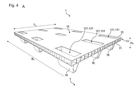
Fig. 4 are schematic representations of a pallet according to the
invention with
feet;
Fig. 5 are schematic representations of a pallet according to the
invention with
runners;
Fig. 6 is a schematic representation of a sandwich block according to the
invention;
Fig. 7 is a schematic representation of feet according to invention;
Fig. 8 are schematic representations of blocks of a runner according
to the
invention.
Figure 1 shows in detail a tube segment 14, which extends along a longitudinal
extension
direction I and comprises a wall 145 as well as two cut ends 141, 142
delimiting the wall
145 in the circumferential direction of the tube segment 14. In addition, the
tube segment
14 comprises two cut surfaces 143, 144, which delimit the tube segment 14 in
the
longitudinal extension direction I.
The tube segment 14 comprises a segment depth t in the direction of the
longitudinal
extension direction I, a segment width b corresponding to the maximum
extension in the
direction of a connecting line between the cut ends 141, 142, and a segment
height h
corresponding to the maximum extension in the third spatial direction
perpendicular to the
segment width b and the segment depth t.
In the embodiment shown here, the tube segment 14 comprises an octagon segment
shaped cross-section transversely to the longitudinal extension direction I.
The tube
segment 14 is composed of five strips running along the longitudinal extension
direction I,
which each have an angle of 45 to the adjacent strip or strips.
As an alternative to the embodiment shown in Figure 1, the tube segment 14 may
also
comprise a differently shaped cross-section, in particular a circular-segment-
shaped
cross-section, e.g. semicircular, trapezoidal-segment-shaped or U-shaped cross-
section.
Figure 2 shows a layer 13 of a pallet 1 according to the invention composed of
tube
segments 14 and strips 15. Tube segments 14 are arranged in a plurality of
rows 132 in
CA 03031843 2019-01-24
32
the direction of pallet width Bp, rows 132 being stacked in the direction of
pallet depth Tp.
The tube segments 14 are positioned in such a way that the segment widths b
run in the
direction of the pallet width Bp and the segment heights h run in the
direction of the pallet
depth T. The segment depths t run in the third spatial direction not shown.
The
designations for segment width b, segment height h and segment depth t are to
be taken
from the illustration of the tube segment 14 in Figure 1.
In each case a first row 132a and a second row 132b are mechanically connected
to a
corresponding strip 15, wherein the cut ends 141,142 (see Fig. 1) of the tube
segments
14' of the first row 132a are mechanically connected to a first strip side 151
of the strip 15,
and wherein the tube segments 14" of the second row 132b are mechanically
connected
to a second strip side 152 of the strip 15 opposite the first strip side 151.
Therein, the tube
segments 14' of the first row 132a are rotated 180 about an axis which runs
along the
longitudinal extension direction I with respect to the tube segments 14" of
the second row
132b. The tube segments 14" of the second row 132b are mechanically connected
to the
tube segments 14 of an adjacent row 132, whereby the walls 145 (see Fig. 1) of
the tube
segments 14" of the second row 132b are connected to the walls 145 of the tube
segments
14 of the adjacent row 132.
Layer 13 comprises a plurality of cutouts 131, each formed by omitting tube
segments 14.
The cutouts 131 shown here are formed by omitting three or four tube segments
14 in the
direction of pallet width Bp and two tube segments 14 in the direction of
pallet depth Tp.
Accordingly, the cutouts 131 each have an extension of three or four segment
widths b in
the direction of the pallet width Bp and an extension of two segment heights h
in the
direction of the pallet depth T.
Figure 3 shows a first panel 11 for a pallet 1 according to the invention. The
first panel 11
comprises a plurality of first openings 111 arranged in such a way that they
can be at least
partially aligned with the cutouts 131 of a layer 13 of pallet 1. In the case
of pallet 1
embodiments where the second panel has 12 second openings 121, the second
panel 12
may be formed in the same way as the first panel 11 shown here.
CA 03031843 2019-01-24
33
Figure 4A shows a pallet 1 according to the invention in an embodiment with
feet 16 in a
perspective view from the top of pallet 1. Pallet 1 comprises a layer 13
arranged between
a first panel 11 and a second panel 12. Layer 13 is structured in the same way
as layer
13 shown in Figure 2. The segment depths t of the tube segments 14 of layer 13
run in
the direction of a pallet height Hp. Furthermore, cutouts 131 of layer 13 are
shown, which
overlap with second openings 121 of the second panel 12. Therein, the second
openings
121 are narrower in the direction of pallet depth Tp than the corresponding
cutouts 131 in
the direction of pallet depth Tp. As a result, the supporting elements 161 of
the feet 16
(see Figure 7) are arranged in corresponding gaps between the second panel 12
and the
tube segments 14 adjacent to the corresponding cutout 131. When stacking
several
pallets 1 according to the invention, for example, the feet 16 of another
pallet 1 can be
inserted into the cutouts 131, which are open at the top, which allows space-
saving
stacking.
Figure 4B shows a perspective view of the underside of pallet 1 shown in
Figure 4A. This
view shows the first openings 111 of the first panel 11 in which the feet 16
are inserted.
Figures 5A and 5B show a pallet 1 according to the invention in an embodiment
with
runners 17 in a perspective view, whereas Figure 5A shows a view from the top
and Figure
5B shows a view from the bottom of pallet 1. Layer 13 is structured in the
same way as
layer 13 shown in Figure 2.
The runners 17 each comprise a bottom board 171 mechanically connected to
three
blocks 172. The blocks 172 are inserted into the (hidden) first openings 111
of the first
panel 11, which are not shown here.
Figure 6 shows a sandwich block 2 with a block width BB, a block depth TB and
a block
height HB.
The sandwich block 2 comprises a plurality of plies 20 of tube segments 14,
the plies being
stacked on top of each other in the direction of the block height HB. The tube
segments 14
are positioned in such a way that the longitudinal extension direction I of
the tube
CA 03031843 2019-01-24
34
segments 14 or the segment depth t runs in the direction of the block depth TB
and the
segment width b runs in the direction of the block width BB.
In each case a first ply 20a and a second ply 20b are mechanically connected
to a
corresponding intermediate plate 22, wherein the cut ends 141,142 (see Fig. 1)
of the tube
segments 14" of the first ply 20a are mechanically connected to a first plate
side 221 of
the intermediate plate 22, and wherein the tube segments 14" of the second ply
20b are
mechanically connected to a second plate side 222 of the intermediate plate 22
opposite
the first plate side 221. Therein, the tube segments 141" of the first ply 20a
are rotated 1800
about an axis running along the longitudinal extension direction I with
respect to the tube
segments 14' of the second ply 20b. The tube segments 14" of the second ply
20b are
mechanically connected to the tube segments 14 of an adjacent ply 20, whereby
the walls
145 (see Fig. 1) of the tube segments 14" of the second ply 20b are connected
to the
walls 145 of the tube segments 14 of the adjacent ply 20.
Sandwich block 2 comprises a plurality of through holes 21 continuous in the
direction of
the pallet depth Tp, each formed by omitting tube segments 14. The through
holes 21
shown here are formed by omitting three or four tube segments 14 in a ply 20,
with the
tube segments 14 omitted at respective positions of two adjacent superimposed
plies 20.
This results in through holes 21 with an extension of three or four segment
widths b in the
direction of the block width BB and two segment heights h in the direction of
the block
height HB.
By separating the sandwich block 2 shown here transversely to the longitudinal
extension
direction I of the tube segments 14, i.e. in a plane running between the block
width BB and
the block height HB, a layer 13 can be created for a pallet 1 according to the
invention.
Such a layer 13 is shown in Figure 2. In particular, a slice is cut off from
sandwich block
2, where layer 13 is formed by the slice. When cutting, new cut surfaces
143,144 (see Fig.
1) of the tube segments 14 are formed. The pallet width Bp of a pallet 1
formed by means
of the layer 13 created corresponds to the block width BB, the pallet depth Tp
corresponds
to the block height HB and the pallet height Hp is freely selectable during
cutting and is
defined in particular by the thickness of a disc cut off from the sandwich
block 2.
CA 03031843 2019-01-24
Figure 7A shows two perspective views of a foot 16 for a pallet 1 according to
the invention
in a folded form. The foot 16 comprises two supporting elements 161 and a
joining element
162, which mechanically connects the supporting elements 161. Figure 7B shows
foot 16
5 in an unfolded form. In the embodiment shown here, the foot 16 is formed
of strips of a
wood composite, whereby the supporting elements 161 and the joining element
162 can
be formed of a single strip, which has mitres sawn or milled between the
supporting
elements 161 and the joining element 162, as shown in Figure 7B. The
supporting
elements 161 in the embodiment shown here are trapezoidal and have two
parallel sides
10 .. s1,s2, the first side sl being shorter than the second side s2. The
first sides si are
mechanically connected to the joining element 162.
If the foot 16 is folded or rotated as shown in Figure 7A, a preload of the
foot 16 can be
generated by applying a force, so that in particular the foot 16 can be
inserted into the
15 cutout 131 under the preload through the at least one second opening 121
of the second
panel 12. When the preload is released, the foot 16 opens at least partially
so that the
supporting elements 161 form a positive connection with the inside of the
second panel
12 or with the tube segments 14 of the layer 13.
20 Figure 8A shows two versions of a block 172 according to the invention
for a runner 17 of
a pallet 1 according to the invention and Figure 8B shows an intermediate
product from
which several blocks 172 can be produced by cutting.
The blocks comprise a first cover plate 173, a second cover plate 174 and a
core layer
25 175 arranged between the cover plates 173, 174, which comprises a first
partial layer 176
and a second partial layer 177 of tube segments 14. The tube segments 14 of
the first
sublayer 176 are mechanically connected to the first cover plate 173 by their
cut ends 141,
142 (see Fig. 1) and the tube segments 14 of the second sublayer 177 are
mechanically
connected to the second cover plate 174 by their cut ends 141, 142. The first
and the
30 second sub-layer 176, 177 are mechanically connected via the walls 145
(see Fig. 1) of
the tube segments 14. The embodiments shown comprise three or four parallel
tube
segments 14 per sublayer 176,177.
CA 03031843 2019-01-24
36
List of reference numerals
1 Pallet
Basic body
11 First panel
111 First opening
12 Second panel
121 Second opening
13 Layer
131 Cutout
132 Row
132a First row
132b Second row
14,14`,14",14¨,14" Tube segment
141,142 Cut ends
143,144 Cut surface
145 Wall
Strip
151 First strip side
152 Second strip side
16 Foot
161 Supporting element
_
162 Joining element
17 Runner
171 Bottom board
4-
172 Block
173 . First cover plate
174 Second cover plate
175 Core layer
176 First partial layer
177 Second partial layer
-
2 Sandwich block
CA 03031843 2019-01-24
37
20 Ply
20a First ply
20b Second ply
21 Through hole
22 Intermediate plate
221 First plate side
222 Second plate side
Longitudinal direction
Segment breadth
Segment depth
Segment height
Bp Pallet breadth
Tp Pallet depth
Hp Pallet height
BB Block breadth
TB Block depth
HB Block height
Si First side
Second side