Note: Descriptions are shown in the official language in which they were submitted.
CA 03032311 2019-01-29
WO 2017/024360 PCT/AU2016/050749
LIQUID COLLECTION DEVICE
Field of the invention
This invention relates generally to the collection of liquid samples for
analysis and more particularly to microfluidic devices for collecting blood or
other fluid samples from patients for simultaneous or subsequent diagnosis. In
one or more embodiments, the invention provides a pen format liquid collection
device that has application to the collection of blood micro samples from pin
prick blood spots.
Background to the invention
The conventional method of obtaining diagnostic blood samples from
patients necessarily involves a medical professional who either employs a
hypodermic syringe or fits a temporary cannula to the patient's arm and draws
off a succession of discrete samples into separate vials, each typically
dedicated to one or more specific analyses. With a trend to smaller sample
volumes, a number of microfluidic point of care diagnostic devices have been
developed for a range of analytic purposes. Most such devices are relatively
costly and complex to operate and, while avoiding the need to transport blood
samples for analysis in laboratory settings, still require operation by
skilled
medical staff. It would be advantageous to the delivery of healthcare if
microfluidic blood samples could be collected by relatively untrained
personnel
or even by patients themselves. Devices for self-testing of blood sugar level
and
home pregnancy kits are examples of successful products in which untrained
individuals can perform diagnostic tests on themselves, in one case utilising
finger prick blood spots and in the other urine collection.
In a paper entitled lab-in-a -pen: a diagnostics format familiar to
patients for low-resource settings' at Lab Chip 2014, 14, 957, Gong et al
describe a pen format device that incorporates a finger actuable lancet and a
paper assay with a collection pad adjacent the lancet blade. Prior to and
after
deployment, an end cap covers the exposed lancet blade and collection pad.
US patent 4,360,016 discloses a not dissimilar pen format blood
collection device for the specialised purpose of foetal blood sampling. The
finger actuable lancet pierces the skin on the head of the foetus and blood is
collected in an adjacent capillary tube. This tube is detachably mounted by
clips
at a fixed position, that places an open end of the tube below the lancet
blade
when deployed.
1
CA 03032311 2019-01-29
WO 2017/024360 PCT/AU2016/050749
It is an object of the invention to provide a pen format liquid collection
device that provides one or more advantages relative to the aforedescribed
devices.
Reference to any prior art in the specification is not an acknowledgment
or suggestion that this prior art forms part of the common general knowledge
in
any jurisdiction or that this prior art could reasonably be expected to be
combined with other pieces of prior art by a skilled person in the art.
Summary of the invention
It has been appreciated that prior proposed devices such as those
discussed above have significant limitations, most notably exposure of the
blood collection element to potential contamination. There is also a potential
for
needle stick injuries from the lancet components of the devices.
In a first aspect, the invention provides a pen format liquid collection
device that includes an elongate generally tubular housing able to be held by
hand and having an opening at one end, and at least one liquid take-up element
mounted in the housing so as to be positioned or positionable to project at
the
opening, the at least one liquid take-up element then further postionable by
hand manipulation of the housing to contact a volume of liquid to thereby take-
up a sample of the liquid to be analysed. At least one retention element is
supported in the housing. The at least one liquid take-up element and the at
least one retention element are arranged whereby they are relatively movable
into contact, and the at least one retention element is adapted on contact to
in
turn take-up the sample and retain the sample or a component thereof for in
situ
analysis or later recovery while protected within the housing.
In an embodiment, the at least one retention element is supported in a
carrier that is mounted in the housing for sliding movement to bring the at
least
one retention element into contact with the at least one liquid take-up
element.
The carrier may be a cartridge recoverable from the housing for subsequent
analysis of the sample or component thereof.
The device may further include a detachable cover about the projecting
portion of the at least are liquid take-up element. This cover may also
provide a
base for supporting the device upright on a surface.
In an embodiment, the cover includes interengagable formations for
locking the cover to the housing after a sample has been taken-up to prevent
re-use of the device.
2
CA 03032311 2019-01-29
WO 2017/024360 PCT/AU2016/050749
Preferably, the at least one liquid take-up element and the at least one
retention element are arranged whereby they are relatively movable into
contact
by hand action.
In an embodiment liquid take-up element is mounted for respective first
and second movements, wherein the first movement is from a first retracted
condition within the housing to an extended condition at the opening in which
the liquid take-up element is postionable, by hand manipulation of the
housing,
to contact a volume of liquid to thereby take-up a sample of the liquid to be
analysed, and wherein the second movement is from the extended condition to
a second retracted condition within the housing in contact with the at least
one
retention element. The respective first and second retracted conditions may be
co-incident.
In an embodiment, the at least one liquid take-up element may be an
absorbent body of material selected to absorb a sample of the liquid on
contact
with the volume of liquid.
In another embodiment, the at least one liquid take-up element is a
capillary open at a first or distal end that in operation contacts said volume
of
liquid and at a second or proximate end that in operation contacts the at
least
one retention element.
The at least one retention element is preferably an absorbent body
selected to absorb the whole of the sample from the at least one liquid take-
up
element when the two contact.
The sample may be of a pre-determined or prescribed volume.
In an embodiment, there are plural said liquid take-up elements within
the housing, for example three or more equi-angularly arranged about the
housing. Plural said retention elements may be contactable with the respective
liquid take-up elements.
In a second aspect, the invention provides a pen format liquid collection
device, that includes an elongate generally tubular housing able to be held by
hand and having an opening at one end, and a plurality of capillary liquid
take-
up elements in the housing postionable, by hand manipulation of the housing,
to
contact a volume of liquid to thereby take-up a predetermined total volume of
a
sample of the liquid to be analysed, wherein the capillary liquid take-up
elements are configured to take-up by capillary action respective
predetermined
volume portions of the sample and notwithstanding gravity to retain the
portions
in any orientation of the respective elements. At least one retention element
is
supported in the housing positional3le to contact the capillary take-up
elements
CA 03032311 2019-01-29
WO 2017/024360 PCT/AU2016/050749
and adapted on contact to in turn take-up the sample and retained the sample
or a component thereof for in situ analysis or later recovery while protected
within the housing.
The at least one retention element may be supported in a carrier that is
mounted in the housing for sliding movement to bring the at least one
retention
element into contact with the plurality of capillary liquid take-up elements.
The
carrier may be a cartridge recoverable from the housing for subsequent
analysis
of the sample or component thereof.
Each capillary liquid take-up element is preferably open at a first or
distal end that in operation contacts said volume of liquid and at a second or
proximate end that in operation contacts the at least one retention element.
In another aspect of the invention, the capillary liquid take-up elements
may each have a liquid collection volume in the range 1 to 10 pL, for example
in
the range 2 to 5 pL.
In a third aspect, the invention provides a pen format liquid collection
device, comprising:
an elongate generally tubular housing able to be held by hand
and having an opening at one end;
a liquid take-up element mounted for respective first and
second movements, wherein the first movement is from a first retracted
condition within the housing to an extended condition at said opening in
which the liquid take-up element is positionable, by hand manipulation
of the housing, to contact a volume of liquid to thereby take up a sample
of the liquid to be analysed,
and wherein said second movement is from the extended
condition to a second retracted condition within said housing in which
the sample taken up is retained for in situ analysis or later recovery
while protected within the housing from contamination; and
a hand operable actuator for effecting said first and second
movements.
In an embodiment, the liquid take-up element is an absorbent body of
material selected to absorb a sample, preferably a prescribed volume thereof,
of
the liquid on contract with said volume of liquid. In an alternative
embodiment,
preferred for applications such as blood collection, the liquid take-up
element is
a capillary tube open at a distal end that contacts said volume of liquid in
its
extended condition and is arranged to contact a respective absorbent body in
its
4
CA 03032311 2019-01-29
WO 2017/024360 PCT/AU2016/050749
second retracted condition, the absorbent body being selected to absorb the
whole of the sample from the capillary tube when the tube is in the second
retracted condition. With this arrangement, a pre-determined sample volume is
taken up, determined by the retention volume of the capillary tube.
The respective first and second retracted conditions are preferably co-
incident.
Preferably, there are plural liquid take-up elements within said housing,
for example three or more equi-angularly arranged about the housing. There
may be separate actuators for each element or a single actuator mechanism
with respective selectable settings corresponding to each element.
In an advantageous embodiment of the invention, in any of its aspects,
the pen format liquid collection device further includes a lancet mechanism
including a blade projectable from the opening at said one end of the housing.
A
device thus configured may be employed to effect a finger prick and
immediately collect a plurality of blood samples corresponding to the number
of
liquid take-up elements provided in the housing, or alternatively be employed
to
collect separate blood samples from different locations or at different times.
Advantageously, the device is configured so that the blood sample(s)
can only be recovered by a designated person employing a designated tool.
Preferably, in the device containing plural liquid take-up capillary tubes,
the
absorbent bodies are contained within a discrete sub-housing from which they
are removable for recovery of the samples and analysis thereof. For this
purpose, the housing is in plural separate parts and slidably receives the
absorbent body sub-housing.
The invention also extends to any combination of the first, second and
third aspects, or of their optimal and preferred features.
As used herein, except where the context requires otherwise the term
'comprise' and variations of the term, such as 'comprising', 'comprises' and
'comprised', are not intended to exclude other additives, components, integers
or steps.
Brief description of the drawings
The invention will now be further described, by way of example only,
with reference to the accompanying drawings, in which:
Figure 1 is an axial cross sectional view of a pen format blood
collection device according to a first embodiment of the invention, depicted
CA 03032311 2019-01-29
WO 2017/024360 PCT/AU2016/050749
before, during and after deployment to recover a blood sample from a pin prick
volume of blood;
Figure 2 is a perspective view of a pen format blood collection device
according to a second embodiment of the invention, capable of recovering and
retaining four discrete blood samples;
Figures 3A and 3B are a pair of exploded views of the device
illustrated in Figure 2;
Figure 4 is a fragmentary cross section of the device illustrated in
Figures 2, 3A and 3B, depicted before and during deployment;
Figure 5 is a perspective view of a pen format blood collection device
according to a third embodiment of the invention incorporating a lancet for
obtaining a pin prick volume of blood;
Figure 6 is an exploded view of the device depicted in figure 5,
Figure 7 is a perspective view of a pen format blood collection device
according to a fourth embodiment of the invention, together with a dual
purpose
cover and support base and an associated package for delivery of the device to
a point of use and return for analysis of one or more contained blood samples;
Figure 8 shows the embodiment of Figure 7 and its mode of
engagement with the dual purpose cover and support base;
Figure 9 is an axial cross-section of the device of Figures 7 and 8;
Figure 10, 11 and 12 are respective 3-dimensional component views of
the capillary tube sub-assembly, the cartridge containing the absorbent pads,
and the integral spring structure; and
Figure 13 is a fragmentary englargement of region A in Figure 9.
Detail description of embodiments
The pen format blood collection device 10 illustrated in Figure 1 is
designed to recover and retain a single blood sample of a predetermined micro
volume, for example in the range 5 to 30p1. A volume of 15p1, e.g, is commonly
accepted as necessary but sufficient for dry blood spot analysis. The
embodiment is essentially a ballpoint pen modified by replacing the ink ball
with
a liquid take-up element in the form of a liquid take-up element comprising a
cylindrical body of absorbent material selected, both as to substance and
dimensions, to absorb 15l of blood. A suitable such material is a porous
polymer substrate, a hydrophilic cellulose paper, a monolith polymer, or any
equivalently performing inert porous material.
6
CA 03032311 2019-01-29
WO 2017/024360 PCT/AU2016/050749
Other than absorbent liquid take-up element 30, the device 10 includes
the usual features of a pen mechanism, including a generally tubular housing
or
barrel 12 that is of substantially uniform diameter at its rear end and gently
tapers at its front end to a conical tip 14 with a central end opening 15. The
mechanism includes a coaxial plunger 16 (which in a pen also serves as the
ink-containing tube), a return spring 19 under compression between respective
shoulders 19a and 19b on housing 12 and plunger 16, and a push button
mechanism 22. Mechanism 22 has an internal cam device 26 whereby, when
push stem 23 is depressed by finger or thumb, the plunger 16 is pushed to and
held in an extended position and when push stem 23 is again depressed this
position is unlatched and spring 19 pushes the plunger back to its retracted
position.
The forward end of plunger 16 is sealed off and fitted with a liquid
absorbent to form liquid take-up element 30, which is slidably smoothly guided
by a bore 28 of complementary radius extending back from opening 15. In the
retracted position of plunger 16 and therefore of liquid take up element 30,
the
liquid take-up element is disposed as illustrated in Figure 1(a): it is
protected
from contamination prior to use by having its front tip recessed along bore 28
behind opening 15.
When it is time to collect the blood sample from a finger or thumb 80 or
any other suitable location on the skin surface of an individual, a suitable
lancet
(not shown) is employed to puncture the skin to form a pin prick 82 from which
a
small volume of blood 84 pools on the skin 81 (Figure 1(b)). Collection device
is prepared to recover a blood sample by depressing push stem 23 to move
liquid take-up element 30 forwardly so that it reaches its extended condition
at
and protruding from opening 15. The housing of device 10 is now manipulated
to bring element 15 into contact with the volume of pooled blood 84 whereupon
the absorbent material of element takes up therefrom a sample of the blood
(Figure 1(b)). After an appropriate time, the device is withdrawn and push
stem
23 is pushed to retract liquid take up element 30 and its entrained blood
sample
into housing 12 behind opening 15. In this retracted condition (Figure 1(c)),
element 30 now serves as a retention or absorbent element retaining the taken
up blood sample for later recovery and analysis while in the meantime
protected
from contamination.
The embodiment of Figurel is satisfactory for more qualitative
applications, e.g. analysis as to whether a blood sample does or does not
contain a particular virus or other marker. For more quantitative analyses,
e.g.
detection of protein markers such as haemoglobin Al c (HbAl c), where a known
7
CA 03032311 2019-01-29
WO 2017/024360 PCT/AU2016/050749
volume of blood is required, the application of the embodiment of Figure 1
will
be reliant upon the take-up or absorbent element 30 consistently taking up a
prescribed volume of blood. While certain manufacturers claim that this is so,
it
is found in practice that the actual volume taken up by liquid absorbent
material
is dependent upon the haematocrit of the blood, which varies considerably
between individuals within a wide normal range. The embodiment 110 of
Figures 2 to 4 addresses this uncertainty by providing the take-up element as
a
glass capillary tube and providing an absorbent retention element as a
separate
component. This embodiment also demonstrates a more complex device
capable of recovering and retaining four discrete samples.
Continuing the pen format, the four sample device 110 of Figures 2-4
has a structure inspired by a 4 colour ballpoint pen. In Figures 2-4,
corresponding elements relative to the embodiment of Figure 1 are depicted
with similar reference numerals preceded by a "1".
Device 110 includes a generally tubular housing or barrel 112 of
"rounded square" cross section with a main section 113 and a separate nozzle
cap 114. Nozzle cap 114 has a slight taper and a rearward skirt 114a by which
it fits into the end of the main section 113 of housing 112. Nozzle cap 114,
which is somewhat more blunt nosed than the tip 14 of housing 112 retains
within it a glass capillary mount 140 and a blotting paper support 160. The
whole structure has a 4-way angular symmetry with an identical discrete
mechanism for each quarter to recover and retain a discrete blood sample.
To this end, glass capillary mount 140 is a moulded unitary piece with a
base wall 141 and a cross-shaped partition structure 142 that defines four
longitudinally extending compartments 143. Each compartment 143 slidably
mounts a sector block 144 with an inner and outer bore. The inner bore
receives and is fixed to an open-ended liquid take-up element in the form of a
glass capillary tube 130 of an internal volume equal to the desired volume of
blood, e.g. 15p1. This glass capillary tube 130 projects slightly rearwardly
from
end wall 141.
The outer bore in sector block 144 is a blind bore at its rear, located
axially outwardly of glass capillary tube 130. This blind bore receives and is
fixed to the forward end of a plunger 116 that is slidable to move sector
block
144 and therefore glass capillary tube 130 forwardly and rearwardly in chamber
143.
Blotting paper carrier or cartridge 160 is a rounded square integral plate
with a peripheral rim 161 at its rear against which abuts the skirt 114a of
nozzle
cap 114. Blotting paper carrier 16Cshas four equiangular spaced inner bores
CA 03032311 2019-01-29
WO 2017/024360 PCT/AU2016/050749
162 that mount cylindrical retention elements, ie. absorbent bodies 130a, and
are aligned to be contacted by the rear open end of glass capillary tubes 130,
when in their rearmost or retracted position. In this case, absorbent
retention
elements 130a are blotting papers selected to absorb and retain blood samples.
Four outer bores 163 in carrier 160 slidably receive plungers 116.
The rear face of blotting paper carrier 160 mounts a hydrophilic silica
gel capsule 165 for absorbing moisture from the blood samples on blotting
paper absorbent retention elements 130a, for drying the blood samples while
they are in situ within the device and readying them for dried blood spot
analysis.
The respective plunger mechanisms for selectively moving the glass
capillary tubes 130 are similar to those in a standard 4-colour ballpoint pen
and
include a retracting spring 119 about each glass capillary tube 130 and
respective push clips 123 in side slots 123a of housing 112. Plungers 116 are
located and guided by a central plunger guide 125 within the housing. The
mechanism further includes a cam interaction 123b between the push clips 123
whereby depressing one will release and cause retraction of an already
extended plunger under the action of its respective spring 119.
Figure 4a illustrates the device of Figures 2 and 3 in a fully retracted
condition ready for deployment. When it is desired to collect a blood sample,
a
selected clip 123 is depressed and pushed forwardly to push the corresponding
plunger 116 and sector block 144 to move the associated glass capillary tube
130 against its spring 119 through a respective opening 115 in the blunt tip
of
nozzle cap 114. The glass capillary tube is now in its extended condition at
opening 115 and is positionable by hand manipulation of housing 112 to contact
a volume of blood obtained by a pin prick to take-up, through its open front
end,
a sample of the blood by capillary action. The sample fills the capillary tube
and
is of a fixed and predictable volume determined by the tube.
On depression of a different push clip 123, the projected plunger is
released and the glass capillary tube retracted by its spring 119 from the
extended condition to its retracted condition in which the open rear end of
the
glass capillary tube contacts respective blotting paper absorbent element
130a,
which promptly takes up the entire blood sample and empties the glass
capillary
tube. The blood sample is thereby now retained within the housing for later
recovery while protected in the meantime from contamination. Nozzle cap 114
is at least partly transparent to allow clear sighting of the filling and
emptying of
the capillary tube.
9
CA 03032311 2019-01-29
WO 2017/024360 PCT/AU2016/050749
When the desired number of blood samples, at least one up to four in
the embodiment as illustrated, have been collected, the device can be opened
onsite by an authorised person or forwarded to another site for opening.
Typically, this will require removal of nozzle cap 114 in a suitable
environment,
recovery of the blotting paper carrier 160 and extraction or punching out of
the
blotting paper absorption elements 130a by known means. The engagement of
nozzle cap 114 to close the housing may desirably entail use of a specialised
tool not readily available to the person originally collecting the blood.
Figures 5 and 6 depict a third embodiment of pen format liquid
collection device 210 which includes a central lancet device 270 for obtaining
the pin prick blood volume to be taken up by the capillary tubes 230. In these
figures, like parts relative to the first and second embodiments are indicated
by
like reference numerals preceded by a "2". The details of the mechanism are
not fully illustrated but it is noted that this embodiment includes a
rotatable
lancet depth adjustment dial 272 and a lancet actuator button 274 on the side
of
the main housing 212. Rather than having separate push clips 123 as in the
second embodiment, the rear of the housing is fitted with an actuator button
223
that is rotatable to select a glass capillary tube and then depressed to move
the
selected glass capillary tube 230 to its extended or deployed position for
taking
up blood from the volume extracted by the lancet device 270. As in the
previous embodiment, the liquid absorbent retention elements are in the form
of
blotting paper elements 230a retained in a separate carrier component 260.
The device 10, 110 or 210 preferably includes a feature that prevents
deployment of the liquid take-up element 30, 130, 230 more than once.
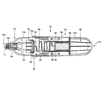
Figures 7 to 13 depict a fourth embodiment of pen format liquid
collection device 310 which uses a single mechanism to transfer the contents
of
four blood capillaries simultaneously onto four independent absorbent pads. In
this embodiment, like parts relative to the earlier illustrated embodiments
are
indicated by like reference numerals preceded by a "3". The pen 310 is
positioned in a cover/base 400 in a disengaged position and is transported in
a
plastics package 311 that includes a sealing lid 311a ¨ the pen and base are
held in position together using an adhesive patch 402. Once the pen is removed
from the package 311 it is placed on the base 400 in an upright position
(Figure
8).
This embodiment differs from the earlier embodiments in that a blotting
paper carrier or cartridge 360 and the glass capillary tubes 330 are
relatively
movable to bring the absorbent retention elements 330a into contact with the
inner ends of the glass capillary tu'iloG 330, whereas in the earlier
embodiments,
CA 03032311 2019-01-29
WO 2017/024360 PCT/AU2016/050749
the absorbent retention elements were fixed in position and the capillary
tubes
were longitudinally individually movable.
Device 310 includes a generally tubular housing or barrel 312 with
opposed side flats 312a to facilitate manual gripping. The housing is in two
parts: a main section 313 with a rounded closed rear end 313e and an open
front rim 313a that receives a cylindrical skirt 314a of a front cap section
314.
Engagement between respective peripheral shoulders 361a, 361b on housing
sections 313, 314 (Figure 13) prevent their separation except when snapped
apart by force but the two sections can telescopically move towards each other
for a purpose that will become clearer.
In this case, the four liquid take-up elements in the form of glass
capillary tubes 330 are carried by a glass capillary amount 340 best seen in
Figure 10 to form a capillary tube sub-assembly 335. Mount 340 has four
peripherally spaced identical segments that retain the glass capillary tubes
in a
rearwardly splayed fashion in front press fit notches 340a and rearward
appropriately apertured integral holders 340b. The glass capillary mount is
fixedly retained within an open neck portion 314c of housing cap section 314
so
that, in this embodiment, the four tubes protrude from the front neck portion
opening 315 of the housing to form a close spaced square array at their tips
330d.
Blotting paper carrier or cartridge 360 is generally similar to that of the
second embodiment: a rounded square integral plate 361 with four angularly
spaced tubular cup supports 362a. These supports define bores 362b lined with
longitudinal ribs 363c that in turn define seats for disc-like liquid
absorbent
retention elements or pads 330a of one of the materials discussed earlier, or
other suitable material. The ribs 362c are flared and aligned to receive the
rear
open ends of glass capillary tubes 330 when the support 360 is at its foremost
position. Again in this case, retention elements or pads 330a may be blotting
papers selected to absorb and retain blood samples.
The rib structure allows the pads 330a some adjustment along the
bores to compensate for different alignments that cause the pads to be
contacted by tubes 330 at different times. Other arrangements might include
providing individual spring loading for cup supports 362a or cross-balancing
them in pairs.
Blotting paper carrier or cartridge 360 is detachably retained, by
opposed resiliently deflectable hooks 382, on a front circular pad 384 of a
complex spring structure 380. Spring structure 380 is an integral moulded
piece
of the form depicted in Figure 12. iihas a rear end plate 386 located on a
ledge
CA 03032311 2019-01-29
WO 2017/024360 PCT/AU2016/050749
defined by ribs 313d of housing section 313, and also has a box-like pedestal
387 that defines a central chamber 388 for retaining a hydrophilic silica gel
desiccant capsule 365. This capsule is for absorbing moisture from the blood
samples on blotting paper retention elements 330a, for drying the blood
samples while they are in situ within the device and readying them for dried
blood spot analysis. The interior of housing section 313 behind end plate 386
is
a suitable chamber 385 for any desired control or recordal electronics, e.g
for
time and date stamping use of the device.
Spring structure 380 has three resilient elements to smoothly bias
cartridge 360 into contact with capillary tubes 330 while also allowing for
variations in the relative positions of the blotting papers and the inner ends
of
the capillary tubes. These features include a zig-zag central web structure
383
atop pedestal 387 integrally connecting the pedestal and pad 384, and
substantially sinusoidal filament elements 389 at each side.
The device 310 is delivered in package 311, protected from
contamination. It is prepared for use by removal from the package and placed
in an upright position on dual purpose cover/base 400, retained by adhesive
patch 402. This cover/base 400 engages an overhanging rim 313a of housing
section 313 to extend about and protect the projecting ends of capillary tubes
330.
A sample of liquid such as blood is collected by removing the pen
format device 310 from its base 400 and bringing its capillaries 330 into
contact
with the pin prick blood drop. Once the capillary tubes are filled, the pen is
returned into position in base 400 and forced into the base by pushing down on
the housing 312. The force of the plunge engages a locking feature 390 (Figure
8) to lockingly engage housing 312 with the base 390, and telescopically moves
housing segments 313, 314 together to bring the blotting papers of carrier 360
into firm resiliently supported contact with the inner open ends of the
capillary
tubes 330: the tubes are received into the bores 362b into engagement with the
blotting paper pads 330a. The spring structure 380 provides adequate but
gentle and transversely variable responsive bias to minimise risk of damage to
the tubes or pads.
Once contact between tube and pad is made, the whole of the liquid in
the tube is wicked into, i.e. flows into and is taken-up by the blotting paper
pad,
where it is safely retained for subsequent recovery and analysis.
Once thus lockingly reengaged in its cover/base, the device 310 cannot
be reused and is typically irretrievable from the base at the blood collection
site.
It must be delivered to an analysisnte where special tooling is employed to
disengage locking feature 390 and allow retrieval of the cartridge 360 from
within the housing. In a preferred configuration, the array of absorbent pads
is
dimensioned to be automatically receivable in one or more standard analytical
instruments. In other arrangements, cartridge 360 may include holes to allow
ejection of pads 330a, or may be configured to serve as a sample well in
analytic processes; or may include electromechanical elements.
In a particular application of the invention, the capillary tubes may be
designed to take up the target liquid by pure capillary action and to retain
the
liquid during subsequent movement or transport notwithstanding the effects of
gravity. It is known that the height a liquid travels inside a capillary,
using
capillary force, is governed by a number of parameters including the
interfacial
tension between the surface of the capillary, the liquid involved, and the
air, the
density of the liquid, and the gravitational force. It can thereby be shown
that,
for a given volume of a liquid (such as blood) to be collected, there are
dimensions of the capillary at which the capillary force is overcome by the
gravitational force. For example, for a larger volume such as 10pL or 20pL,
there are specific capillary dimensions for which the capillary force is
overcome
by the gravitational force and others for which it is not.
A consequence of this observation is that a commonly sought sample
micro-volume, e.g. in the range 10 to 30pL can be collected using a device
such
as device 310 in which the capillary tubes contribute a portion of the desired
liquid volume, e.g. portions of 3pL or 5 pL, for which the capillary draw
action is
more predictable and controllable. Depending on the end application, the
portions of the desired volume can be collected separately, or in an
alternative
embodiment, the blotting paper support 360 may be modified to collect all of
the
liquid portions on a single blotting paper, or the four portions in pairs on
two
blofting papers.
In this fashion, a multiple capillary sub-assembly may be a good
pathway to collect accurate and precise larger volumes of liquid. For example,
a unitary borosilicate glass capillary body might contain 10 bores of 3 pL
each.
The suction of blood within these capillaries can if desired occur via
capillary
action only, until the 10 bores are entirely filled, resulting in 30 pL of
liquid
collected. Indeed, use of the device in an upright orientation would be
recommended. The employment of the 3 pL bores has a number of
advantages: the device can be used at any inclination since capillary force is
the sole suction mechanism, and if used upright there is no risk of air bubble
13
Date Recue/Date Received 2022-08-16
CA 03032311 2019-01-29
WO 2017/024360 PCT/AU2016/050749
formation while collecting liquid. There is no dislodgement of the liquid out
of the
capillary bores when the device is agitated.
More generally, it has been found that aspirating into one end of a
capillary and dispensing at the other end to a contacting retention element
such
as a liquid absorbent paper is an especially effective method of achieving
precision and accuracy in analysis of very small volumes of liquid. This is
all
the more so for liquids such as blood that have a high surface tension.
Aspiration and dispensing from the same end, such as occurs with a pipette,
risks lack of precision arising from minute liquid droplets retained at the
outside
of the orifice, and the contact with a wicking material removes this source of
imprecision at the dispensing orifice.
In a further modification, any of the above described embodiments may
include an in situ analysis element, e.g. a marker responsive strip or optical
analyser, and a display for preceding a result of the analysis. For example,
the
liquid absorbent elements (30, 130, 230a; 330a) may be biosensor elements.
An analysis of particular interest in this context is the protein marker
haemoglobin Al c [HbAl c], now officially endorsed by the American Diabetes
Association (ADA), International Diabetes Federation (IDF), and the European
Association for the Study of Diabetes (EASD) to diagnose diabetes. Other
examples include:
a modified porous substrate for the storage of biological samples such as
described in US patent application 20140127669;
a modified porous substrate that enables separation of the plasma from whole
blood such as described in US patent application 20150211967 Al;
the incorporation as part of the liquid absorbent element of an element for
effecting blood plasma separation e.g. a Vivid plasma separation membrane
(available from Pall Corporation);
the incorporation of a sensor to detect an analyte at the appropriate
concentration in the collected volume of blood or plasma for monitoring
diseases such as diabetes. Examples of appropriate sensors are:
= a glucose sensor as described by Delaney et al, Anal.
Chem. 2011, 83, 1300-1306
= an immunological sensor for monitoring HbAl c using
antibodies like those provided by AbD Serotec
(http://www. abdserotec.cornihba I c-hemaglobin-al C-
antibody. html).
14
CA 03032311 2019-01-29
WO 2017/024360 PCT/AU2016/050749
= a biosensor such as a modified optical fibre equipped with
an appropriate microsphere for "Whispering Gallery Mode"
detection as described by Francios et al, 2013, Optics
Express 21, (19), 22566-22577.
It will be appreciated that the invention is applicable to the collection of
precise and accurate very small (e.g. micro) volumes of a wide range of
liquids
for analysis. It is particularly useful for collecting blood samples,
especially in
the form of the third or fourth embodiment. It will be further appreciated
that
the device can be employed by an individual to collect blood samples from
themselves, or more generally by relatively unskilled personnel to collect
samples without any presence of skilled medical personnel. The liquid take-up
element is maintained in a protected position prior to deployment and the
sample is in turn retained in a manner that protects it from contamination
between collection and recovery for analysis.