Note: Descriptions are shown in the official language in which they were submitted.
CA 03032414 2019-01-29
WO 2018/023107 PCT/US2017/044614
BIOCULAR COMPACT COLLIMATION APPARATUS
RELATED APPLICATION
[0001] This Application claims priority benefit from U.S. Provisional
Application, Serial
Number 62/368,842, filed on July 29, 2016, the disclosure of which is
incorporated herein in its
entirety.
BACKGROUND
1. Field
[0002] The disclosed invention relates to optical imaging systems for
relaying images
rendered on a display.
2. Related Art
[0003] There is always a need for more compact visual systems, especially
in confined
spaces such as a vehicle. An example of such system includes head down display
systems
which include optical imaging that relay an image rendered on a display screen
to a user's eye
in a collimated fashion. One design for such an optical system is described in
US Patent
6,075,651, which relays an image for a single-eye viewing, i.e. monocular.
However, there is
also a need to provide such compact optical systems that enable viewing with
both eyes, i.e.,
binocular system.
SUMMARY
[0004] The following summary is included in order to provide a basic
understanding of
some aspects and features of the invention. This summary is not an extensive
overview of the
invention and as such it is not intended to particularly identify key or
critical elements of the
invention or to delineate the scope of the invention. Its sole purpose is to
present some
concepts of the invention in a simplified form as a prelude to the more
detailed description that
is presented below.
[0005] Disclosed embodiments provide a compact design form that allows for
a small
overall size, while enabling viewing the image with both eyes. In this design
form, to achieve
good optical performance, the system generates a flat field, collimated light,
that is provided on
an aperture sufficiently large to be viewable with both eyes simultaneously.
1
CA 03032414 2019-01-29
WO 2018/023107 PCT/US2017/044614
[0006] In the disclosed embodiments a field flattener lens is used to
generate an image that
is sharp from center to edge, even when utilizing large aperture viewed with
two eyes.
Additionally, a collimating arrangement is used to generate a collimated
display, i.e., the image
is focused at infinity. The design allows for a compact package that utilizes
a thin packaging,
while the collimated nature of the system allows the user to be very close to
the system thus
allowing use in very tight situations (i.e. vehicle). The collimated nature of
the system allows
for insensitivity in high motion environments. Because the display distance is
effectively a
large distance away from the user (collimated) it is not susceptible to
motions and vibrations
that may be experienced in a vehicle.
[0007] According to disclosed aspect, an optical collimating apparatus for
focusing an
image at infinity or at a desired finite distance as viewed by an observer is
provided, the
apparatus comprising: an observation aperture configured for enabling viewing
with two eyes
simultaneously; an image source for producing said image with light of at
least a first rotary
sense of circular polarization; an optical element having a first side
proximate to said image
source; a partially reflective coating deposited on a surface of said optical
element; a field
flattener lens interposed between the image source and the observation
aperture; a quarter wave
plate proximate to a second side of said optical element, said quarter wave
plate altering said
first rotary sense of circular polarization to a first linear sense of
polarization; and a
polarization selective optical element proximate to said quarter wave plate,
said polarization
selective optical element substantially reflecting light of said first linear
sense of polarization
without altering said first linear sense of polarization, and said
polarization selective optical
element substantially transmitting light of a second linear sense of
polarization, wherein said
second linear sense of polarization is orthogonal to said first linear sense
of polarization.
[0008] The surface of said optical element may be concave. The surface of
said optical
element may be equivalent to said first side of said optical element. The
surface of said optical
element may be equivalent to said second side of said optical element. The
optical element
may comprise: a first optical singlet having a first surface and a second
surface; and a second
optical singlet having a first surface and a second surface, said first
surface of said first optical
singlet coupled to said first surface of said second optical singlet, wherein
said partially
reflective coating is interposed between said first surface of said first
optical singlet and said
first surface of said second optical singlet.
2
CA 03032414 2019-01-29
WO 2018/023107 PCT/US2017/044614
[0009] The first surface of said first optical singlet may be concave, said
second surface of
said first optical singlet may be plano, said first surface of said second
optical singlet may be
convex, and said second surface of said second optical singlet may be plano.
The image source
may be comprised of a liquid crystal display transmitting linearly polarized
light and a circular
polarizer for converting said linearly polarized light to at least said first
rotary sense of circular
polarization.
[0010] The image source may be comprised of a liquid crystal display
transmitting linearly
polarized light and a quarter wave retarder element for converting said
linearly polarized light
to at least said first rotary sense of circular polarization. Also, the image
source may be
comprised of a non-polarizing source, a linear polarizing element, and a
circular polarizer for
converting linearly polarized light to at least said first rotary sense of
circular polarization. The
image source may be also comprised of a non-polarizing source, a linear
polarizing element,
and a quarter wave retarder element for converting linearly polarized light to
at least said first
rotary sense of circular polarization.
[0011] The apparatus may further comprise a polarizing element bonded to an
exit surface
of said polarization selective optical element. The apparatus may further
comprise an anti-
reflection coating bonded to an exit surface of said polarizing element. The
apparatus may
further comprise a combiner element to combine said image with a second image
produced by
a second image source, said second image source in the line-of-sight of the
observer, said
combiner element interposed between said second image source and said first
side of said
optical element. The apparatus may further comprising a combiner element to
combine said
image with a second image produced by a second image source, said second image
source in
the line-of-sight of the observer, said combiner element interposed between
said second image
source and said second surface of said first optical singlet.
[0012] The field flattener lens may be interposed between the image source
and the optical
element. The image source may be adhered to the field flattener lens.
[0013] According to further disclosed embodiments, an optical apparatus for
combining a
first image and a second image is provided, the apparatus comprising: a flat
panel display
producing said first image; an inlet aperture for admitting said second image;
a viewing
window configured to enable viewing with both eyes simultaneously; a field
flattener lens
3
CA 03032414 2019-01-29
WO 2018/023107 PCT/US2017/044614
interposed between the flat panel display and the viewing window; a first
optical singlet having
a first surface and a second surface; a second optical singlet having a first
surface and a second
surface, said first surface of said first optical singlet coupled to said
first surface of said second
optical singlet; a partially reflective coating interposed between said first
surface of said first
optical singlet and said first surface of said second optical singlet; a
combiner configured for
reflecting light from the flat panel display and transmitting light from the
inlet aperture; a
circular polarizer proximate to said second surface of said first optical
singlet, wherein said
circular polarizer converts light of said first linear polarization to light
of said first rotary sense
of circular polarization; a quarter wave plate proximate to said second
surface of said second
optical singlet, said quarter wave plate altering said first rotary sense of
circular polarization to
a first linear sense of polarization; and, a polarization selective optical
element proximate to
said quarter wave plate, said polarization selective optical element
substantially reflecting light
of said first linear sense of polarization without altering said first linear
sense of polarization,
and said polarization selective optical element substantially transmitting
light of a second linear
sense of polarization, wherein said second linear sense of polarization is
orthogonal to said first
linear sense of polarization.
[0014] The combiner may comprise: a polarizing beam splitter interposed
between said flat
panel display and said second surface of said first optical singlet, wherein a
portion of said light
of said first linear polarization and within said first wavelength band from
said flat panel
display is reflected by said polarizing beam splitter toward said first
optical singlet, wherein at
least a portion of light from said second image source is transmitted by said
polarizing beam
splitter toward said first optical singlet. The field flattener lens may be
interposed between the
flat panel display and the combiner. The field flattener lens may be adhered
to the flat panel
display.
BRIEF DESCRIPTION OF THE DRAWINGS
[0015] The accompanying drawings, which are incorporated in and constitute
a part of this
specification, exemplify the embodiments of the present invention and,
together with the
description, serve to explain and illustrate principles of the invention. The
drawings are
intended to illustrate major features of the exemplary embodiments in a
diagrammatic manner.
4
CA 03032414 2019-01-29
WO 2018/023107 PCT/US2017/044614
The drawings are not intended to depict every feature of actual embodiments
nor relative
dimensions of the depicted elements, and are not drawn to scale.
[0016] FIG. 1 is an illustration of an embodiment of the invention
utilizing a field flattener
lens, a PS element and a single optical element;
[0017] FIG. 2 is an illustration of an embodiment similar to that shown in
FIG. 1 except
that it uses an optical doublet;
[0018] FIG. 3 is an illustration of another embodiment utilizing a field
flattener lens, a PS
element and an optical doublet;
[0019] FIG. 4 is an illustration of another embodiment using single lens;
[0020] FIG. 5 is an illustration of an embodiment of the present invention
which allows an
image from a first source to be combined with an image from a second source.
DETAILED DESCRIPTION
[0021] Embodiments of the inventive binocular system will now be described
with
reference to the drawings. Different embodiments or their combinations may be
used for
different applications or to achieve different benefits. Depending on the
outcome sought to be
achieved, different features disclosed herein may be utilized partially or to
their fullest, alone or
in combination with other features, balancing advantages with requirements and
constraints.
Therefore, certain benefits will be highlighted with reference to different
embodiments, but are
not limited to the disclosed embodiments. That is, the features disclosed
herein are not limited
to the embodiment within which they are described, but may be "mixed and
matched" with
other features and incorporated in other embodiments.
[0022] A compact, multi-wavelength display system which can be used as a
collimating
display assembly viewable with both eyes simultaneously is provided. In one
embodiment the
optical system is implemented as a small monitor that is collimated to be
presented to the user as
a larger monitor by having the image focused at infinity. Some of the benefits
of this system are
compact size, use a small display to make effectively a larger monitor and the
collimated nature
of the system allows for it to be motion insensitive in locations such as
vehicles.
CA 03032414 2019-01-29
WO 2018/023107 PCT/US2017/044614
[0023] The system utilizes a polarization selective optical element, or PS
element, that
reflects one linear polarization state while transmitting radiation of the
orthogonal linear
polarization state. The PS element is used in combination with a quarter wave
plate and an
optical element, the optical element including a partially reflective surface.
The optical element
may either be a single element or an optical doublet. In the latter
configuration, the partially
reflective surface is at the interface between the two singlets that comprise
the doublet. The
system also includes an image source that either alone, or in combination with
other optical
elements, produces circularly polarized light of the desired rotary sense.
[0024] A field flattener lens is used to improve the image projected from
the viewing screen.
Notably, contrary to using the field flattener lens in a single eye-piece
configuration, here the
field flattener lens is used in a system wherein the image is projected from a
viewing screen that
is viewable by both eyes simultaneously. The field flattening lens is added to
the system to
remove aberrations that may be introduced by the lenses, especially at the
edges of the image.
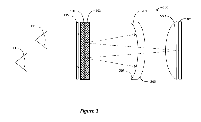
[0025] Figure 1 illustrates the simplest embodiment of the optical device,
showing both
eyes (111) viewing the image on the image source (109), e.g., a flat panel
display, LCD,
OLED, etc. In this particular example the source 109 produces circularly
polarized light. A
combining element (201) is provided with AR coating (205) and partially
reflective coating
(203). In this particular embodiment coating 203 is a dielectric coating with
a transmittance of
approximately 50 percent and a reflectance of approximately 50 percent in the
wavelength
range of interest. The curvature of the surfaces of element 201 is designed to
produce a
collimated image from source 109, for example at a viewing window 115.
Although the
production of a collimated image is the preferred application of the
invention, the system can
also be used for other applications. In addition, there is a retarding element
(103) and a
reflective polarization selective element (101). The retarding element (103)
and a reflective
polarization selective element (101) are made to match the size of the viewing
window 115.
Viewing window 115 is sufficiently large to enable viewing with both eyes
simultaneously.
[0026] In this embodiment a field flattener lens (900) is positioned in
front of display (109).
The addition of field flattener lens (900) with positive power at this
location in the system
flattens the field and makes the image look more like a picture on a wall and
less like a picture
on a curved surface. That is, in this design the goal is to project the flat
image from the flat
6
CA 03032414 2019-01-29
WO 2018/023107 PCT/US2017/044614
image source 109 with minimum aberration at the image's edges. The insertion
of the field
flattener lens ahead of the image source 109 helps achieve this goal.
[0027] In operation, the light from the image source 109 passes through the
field flattener
lens 900 and is preconditioned for the aberrations that will be introduced by
lend 201. A
portion of the light passing through field flattener lens 900 will pass
unheeded through coating
203. The amount of light passed is dependent upon the reflectivity of coating
203. The
polarization of the light passing through coating 203 is unaltered. The
circularly polarized light
passing through coating 203 passes through quarter wave plate 103 causing the
circularly
polarized light to become linearly polarized. The system is designed such that
PS element 101
reflects the particular polarization of the linearly polarized light passing
through polarizer 103.
As the light reflected by PS element 101 passes through quarter wave plate 103
again (in the
reverse direction), the polarization is changed from linear polarization to
circularly polarized
light of the same handedness as the light produced by source 109. A portion of
this light is
reflected by coating 203, the amount reflected being dependent upon the
reflectivity of coating
203. The polarization of the light reflected by coating 203 will be reversed,
thus allowing it to
pass virtually unheeded through the combination of PS element 101 and quarter
wave plate
103. The image created by the light passing through the system depends
primarily upon the
curvature of the surfaces of lens 201. For example, lens 201 can be designed
to form a
collimated image.
[0028] Figure 2 is an embodiment showing lens 201 replaced by a doublet 100
with the
partially reflective surface coating (113) embedded in a doublet (100) that is
made up of two
lens elements (105 and 107) that may or may not be of the same material.
Otherwise the design
is the same as that shown in Figure 1. The curvature of the optical doublet
100 is designed to
produce a collimated image from source 109. Although the production of a
collimated image is
the preferred application of the invention, the system can also be used for
other applications.
Notably, since in this system the doublet 100 introduces fewer element-to-air
interfaces, it is
more efficient than the embodiment of Figure 1.
[0029] In operation, the light from the image source 109 passes through the
field flattener
lens 900 and is preconditioned for the aberrations that will be introduced by
lens 201. A
portion of the light passing through field flattener lens 900 will pass
unheeded through coating
7
CA 03032414 2019-01-29
WO 2018/023107 PCT/US2017/044614
113. The amount of light passed is dependent upon the reflectivity of coating
113. The
polarization of the light passing through coating 113 is unaltered. The
circularly polarized light
passing through coating 113 passes through quarter wave plate 103 causing the
circularly
polarized light to become linearly polarized. The system is designed such that
PS element 101
reflects the particular polarization of the linearly polarized light passing
through polarizer 103.
As the light reflected by PS element 101 passes through quarter wave plate 103
again, the
polarization is changed from linear polarization to circularly polarized light
of the same
handedness as the light produced by source 109. A portion of this light is
reflected by coating
113, the amount reflected being dependent upon the reflectivity of coating
113. The
polarization of the light reflected by coating 113 will be reversed, thus
allowing it to pass
virtually unheeded through the combination of PS element 101 and quarter wave
plate 103. The
image created by the light passing through the system depends primarily upon
the curvature of
coated surface 113. For example, surface 113 can be designed to form a
collimated image.
[0030] Figure 3 illustrates an alternative embodiment employing a field
flattener lens (900)
for enhanced imaging. In this embodiment a field flattener lens (900) is
positioned in front of
image source (109). The addition of field flattener lens (900) with positive
power at this
location in the system flattens the field to avoid aberrations introduced by
the system's lenses.
Also, optionally the image source is adhered to the field flattener lens 900,
thereby eliminating
two element-to-air interfaces.
[0031] This embodiment, as in the embodiment illustrated in FIG. 2, is
comprised of a
plano-convex singlet 105, a plano-concave singlet 107, and a partially
reflective coating 113
interposed between singlets 105 and 107. It is understood that the 105/107
doublet can be
replaced with an element similar to element 201 of FIG. 1 while retaining the
distinctive
features of this embodiment. This embodiment also includes PS element 101 and
quarter wave
plate 103.
[0032] This embodiment of the invention uses an image source 109 that
produces randomly
polarized light. Any number of source types can be used in this embodiment,
for example
source 109 can be a cathode ray tube (CRT), LCD, OLED, etc. The light from
source 109 is
first passed through field flattener lens 900, and is then linearly polarized
with a polarizer 303
and then passed through a quarter wave retarder 305 which circularly polarizes
the image light
8
CA 03032414 2019-01-29
WO 2018/023107 PCT/US2017/044614
to the same rotary sense as that required by the PS element/quarter wave plate
combination. To
reduce reflectance losses, an anti-reflection (AR) coating 307 may be
optionally applied to the
outer surface of polarizer 303. The light which passes through the display
system, including
the PS element/quarter wave plate combination, then passes through an optional
coating stack
in order to improve image contrast and reduce ghosting. This stack is
comprised of a polarizer
309 and an AR coating 311. In an alternate embodiment, polarizer 303 and
retarder 307 are
coupled directly to field flattener lens 900, optionally via index matching
material.
[0033] Figure 3 illustrates an embodiment having a "monolithic" design
form, but its features
can be implemented in a design illustrated in Figure 4, having separate
elements, similar to that of
Figure 1. A polarizer (901) and retarder (902) are positioned in front of the
field flattener lens
(900). The polarizer (901) and quarterwave retarder (902) eliminate some
"unwanted" light in
the system that will not get magnified, which reduces the overall performance
of the system if
not absorbed or managed by these components. A combiner lens (201) with AR
surface
coating (205) and partially reflective surface (203), second retarder (103),
and reflective
selective polarizer (101) are arranged similar to embodiment of Figure 1. A
coverglass (903) is
provided in viewing window 115 for viewing with both eyes simultaneously.
While not shown
in Figure 4, the stack comprising a polarizer 309 and an AR coating 311 can be
implemented in
this embodiment as well.
[0034] Figure 5 illustrates an embodiment having a see though design, i.e.,
allowing an image
from a first source to be combined with an image from a second source. When
used for a heads-up
display, one source is an image source 509 (e.g., LCD, MOLED, etc.) and the
second is the
surrounding environment, which may be viewed via aperture 527.
[0035] The basic system in this embodiment is comprised of image source
509, field flattening
lens 800, plano-convex singlet 501, plano-concave singlet 503, partial
reflective coating 505
interposed between singlets 501 and 503, quarter wave plate 506, PS element
507, and combiner
511. The system also includes AR coating 513 (optional), linear polarizer 515,
and quarter wave
plate 517. Quarter wave plate 517 circularly polarizes the linearly polarized
source light so that it
has the appropriate rotary sense for the quarter wave plate 506/PS element 507
combination. For
improved performance the system also contains polarizer 519 and AR coating
521.
9
CA 03032414 2019-01-29
WO 2018/023107 PCT/US2017/044614
[0036] Many techniques are well known in the art for the fabrication of
combiner 511. For
example, combiner 511 can be a partial reflector which reflects the image from
source 509 into the
line of sight of an observer 525 while simultaneously passing the image of
source 527 to the
observer. Another type of combiner which can be used in this embodiment is a
combiner which has
a wavelength selective reflective coating. Such a combiner is ideally suited
for applications in
which only minimal information is required from source 509. For example,
source 509 may be used
to project markings (eg., targeting system) or instrumentation (e.g., fuel,
air speed, altitude, etc. on a
heads-up display) onto the image from source 527. In such applications only
one or two
wavelengths of light are necessary to provide the information from source 509.
Thus combiner 511
can be designed to only reflect these one or two wavelengths while passing all
other wavelengths of
light. The advantage of this technique is that the reflective coating can be
made very efficient, thus
reflecting most of the radiation of the predetermined wavelengths from source
509 while passing all
but a very small portion of the spectrum radiated by source 527.
[0037] If source 509 is an LCD, then the light emitted by source 509 is
linearly polarized.
Given this light source, in the preferred embodiment of this configuration
combiner 511 is a
polarizing beam splitter which is highly efficient in reflecting the polarized
light emitted by source
509. Given a 90/10 beam splitter, and further assuming that source 527 emits
unpolarized light,
approximately 50 percent of the light emitted by source 527 will be passed by
combiner 511. In this
configuration linear polarizer 515 is not required.
[0038] In general, those skilled in the art to which this invention relates
will recognize that
many changes in construction and widely differing embodiments will suggest
themselves without
departing from the spirit and essential characteristics thereof For example,
the curvature of singlets
105 and 107 may be varied in order to impart different optical powers to the
system. Further,
depending upon the desired application, the shape of the interface between
singlets 105 and 107
may be spherical, aspheric, or plano. Further still, the reflective coating
between the singlets need
not be a 50/50 dielectric coating. Further still, a singlet can be used
instead of the doublet as
previously noted.
[0039] Various embodiments were described above, wherein each embodiment is
described
with respect to certain features and elements. However, it should be
understood that features and
elements from one embodiment may be used in conjunction with other features
and elements of
CA 03032414 2019-01-29
WO 2018/023107 PCT/US2017/044614
other embodiments, and the description is intended to cover such
possibilities, albeit not all
permutations are described explicitly so as to avoid clutter.
[0040] It should be understood that processes and techniques described
herein are not
inherently related to any particular apparatus and may be implemented by any
suitable combination
of components. Further, various types of general purpose devices may be used
in accordance with
the teachings described herein. The present invention has been described in
relation to particular
examples, which are intended in all respects to be illustrative rather than
restrictive. Those skilled
in the art will appreciate that many different combinations will be suitable
for practicing the present
invention.
[0041] Moreover, other implementations of the invention will be apparent to
those skilled in
the art from consideration of the specification and practice of the invention
disclosed herein.
Various aspects and/or components of the described embodiments may be used
singly or in any
combination. It is intended that the specification and examples be considered
as exemplary only,
with a true scope and spirit of the invention being indicated by the following
claims.
11