Note: Descriptions are shown in the official language in which they were submitted.
FOAM-BASED RFID LABEL
TECHNICAL FIELD
[0011 The present invention relates generally to an RFID label for
identifying, tracking,
and/or sensing an article after manufacture, and more particularly, to foam-
based RFID labels
including an RFID device therein disposed between at least one foam layer and
at least one layer
of face material. In a particular application, the foam-based RFID label is
configured to be
affixed to a tire post-vulcanization and remain integral part of the tire
thereafter further aiding in
identifying, tracking, and/or sensing the tire.
BACKGROUND
[0021 Articles are commonly monitored during manufacture and thereafter
for inventory
control purposes, distribution, selling, fleet management, and maintenance. A
common practice
in many fields is to apply a label (e.g., a bar coded label) to an article
containing an identifier or
other information associated with the article (e.g., a tire) having an
identifier or other information
associated with the article.
[003] Tires and a wide array of other rubber-based articles can be
subjected to one or
more vulcanization processes in which the tire or tire components are fused or
molded together.
Vulcanization modifies the rubber-based composition by forming an extensive
network of
crosslinks within the rubber matrix, thereby significantly increasing the
strength and durability of
the article. Although numerous vulcanization techniques are known, many
depending on the type
of curing system in the rubber composition, nearly all techniques include the
application of high
pressure and elevated temperatures to the "green," i.e., non-vulcanized,
rubber-based article.
[004] Adhesive-based labels (e.g., bar coded labels) have been developed
that can be
applied to green rubber-based articles (e.g., tires), which can provide
information related to the
article pre-vulcanization and somewhat during vulcanization. However, during
vulcanization,
these adhesive-based labels are often degraded due to high temperatures and
pressures associated
1
CA 3032445 2019-02-01
with vulcanization and further suffer from "line of sight" limitations in
which a bar code reader
must be place directly over the bar code in order to properly read the label.
[005] While these adhesive-based labels (bar coded labels) are satisfactory
in many
respects, new adhesive labels (bar coded labels) are often required to be
affixed to the vulcanized
article due to the degradation of the original adhesive-based label during
vulcanization. In any
event multiple problems exist with the currently used adhesive-based labels.
For example,
adhesive labels applied pre-vulcanization are not able to remain inextricably
linked during the
lifetime of the tire, and this problem is further observed in the newly
applied adhesive labels (bar
coded labels) applied post-vulcanization of the rubber article as well.
Specifically, vulcanized
tires and/or other vulcanized rubber-based articles are subjected to
considerable stress during use.
Because most conventional adhesive-based labels (bar coded label) are
relatively rigid and
inflexible, the constant flexing, expansion, and contraction (e.g., associated
with movement,
temperature, external factors such as temperature, debris, bumps, water, snow,
ice, inflation
pressure) of the vulcanized rubber-based articles often degrade the adhesive
bond between the
adhesive-based label (bar coded labels) and the vulcanized rubber-based
article. Furthermore
and as mentioned above, these adhesive labels suffer from "line of sight"
limitations in which a
bar code reader must be placed directly over the bar code in order to properly
read the label.
[006] Thus, what is needed is an alternative to conventional adhesive
labels (e.g., bar
coded labels) that overcome the problems discussed above, and more
specifically, what is
needed are foam based RFID labels and methods of affixing these labels to
vulcanized tires such
that these foam based RFID labels remain attached to a rubber-based article
post-vulcanization
(e.g., vulcanized tires) while concurrently providing information about the
tire during
distribution, while in inventory, and/or during the tire's lifetime without
the "line of sight"
limitations of the currently used adhesive labels.
2
CA 3032445 2019-02-01
SUMMARY
[007] In one aspect, the inventive concepts disclosed herein are directed
to a foam-based
radio frequency identification (RFID) labels including an RFID device
disposed, encased, or
sandwiched between at least one layer of foam and at least one layer of face
material. The RFID
label can be applied on and in rubber-based articles, for example tires,
during manufacture (i.e.,
post-vulcanization), and remains inextricably linked thereafter.
[008] In another aspect, the inventive concepts disclosed herein are
directed to a method
of application of a foam-based RFID label during tire manufacture including an
adaptation to a
tire mold and/or post molding by milling a location in which the foam-based
RFID label in
applied.
[009] In a particular aspect, an RFID device may be sandwiched between at
least one or
several layers of foam tape and other materials and at least one layer of face
material. Suitable
face materials include, but are not limited to, polyester films treated to
promote adhesion to the
other layers. In certain aspects, the face layer thickness serves to provide
an appropriate level of
rigidity to the label without compromising overall performance. The face
material can be
printed on and/or colored for identification and branding.
[0010] In yet another aspect, foam and adhesive materials may include, but
are not
limited to, foam tapes such as 3M VHB Tape 4941 P and Avery Dennison Hotmelt
adhesive
TS8000, Acrylic adhesive S3100, and Hybrid adhesive S8049.
[00111 In yet another aspect, the foam-based RFID label is disposed within
a recess in the
tire such that the face of the label is flush with the tire surface.
[0012] In yet another aspect, a flexible curable fluid can be applied to
the space between
the foam-based RFID label and the tire to further attached the label to the
tire and prevent
3
CA 3032445 2019-02-01
separation therefrom.
[0013] In yet another aspect, with appropriate surface preparation, the
foam-based RFID
label can be attached to the inner wall of a tire and thereby not be visually
detectable removing
the potential for manual removal or destruction.
[0014] The foam-based RFID label and methods disclosed herein can be used
to track
production and inventory, among other purposes during the lifetime of the
article.
[0015] In certain aspects, the metallic antenna is an aluminum etched,
printed, wire,
and/or any other RF equipped antenna and integrated circuit or microchip
configured for at least
electronic communication, data memory, and control logic.
100161 Specifically disclosed are methods of installing a foam-based RFID
label in or on
a vulcanized tire including the steps of: (a) forming either during
vulcanization or post-
vulcanization a recess having a predetermined shape on an outermost or
innermost surface (inner
or outer sidewall) of the tire; (b) providing the foam-based RFID label
configured to identify the
tire and/or to sense conditions of the tire and communicate the same to an
RFID reader when
within a predetermined proximity of the RFID reader; and (c) affixing the foam-
based RFID
label within the recess of the vulcanized tire by contacting and adhering an
adhesive surface of
the foam-based RFID label to a surface of the recess to identify the tire
and/or sense conditions of
the tire, wherein: an RFID device is positioned within the RFID label and
disposed between a
foam layer and a face layer that are adhered to one another.
[0017] In certain aspects, the recess is formed during vulcanization by
molding a
predetermined shape within an outermost surface of a sidewall of the tire, the
recess being
defined/formed by a base, a plurality of connected sidewalls, and an opening
formed opposite the
base. In other aspects, the recess is formed by milling an outermost surface
of the tire into a
predetermined shape, the recess having a base, a plurality of connected
sidewalls, and an opening
4
CA 3032445 2019-02-01
formed opposite the base.
[0018] In certain aspects, the adhesive surface of the foam-based RFID
label is adhered to
the base of the recess and completely positioned within the recess such that
the face layer of the
RFID device is flush with or slightly depressed relative to other outermost
surfaces of the
sidewall of the tire. In certain aspects, the RFID device is flush with the
other outermost surfaces
of the sidewall of the tire. In certain aspects, RFID device is slightly
depressed relative to other
outermost surfaces of the sidewall of the tire.
[0019] In certain aspects, the peripheral edges of the foam-based RFID
label are spaced
apart from each sidewall of the plurality of sidewalls of the recess.
[0020] In certain aspects, the method further comprises (d) applying a
concealing
composition over the foam based RFID label to conceal the face layer of the
foam based RFID
label, as well as the all portions of the RFID label, within the
tire/vulcanized tire.
[0021] In certain aspects, the RFID device maintains RFID operability
between 300 MHz
to 3 GHz and identifies and/or senses conditions of the tire and further
communicates the same to
an RFID reader when within the predetermined proximity of the RFID reader.
[0022] In certain aspects, the foam-based RFID label disclose herein is
affixed and/or
adhered on an outer surface of the tire (e.g., a tire sidewall) without being
positioned in a recess.
[0023] In certain aspects, the foam-based RFID label used in the above
discussed method
further includes a first adhesive layer between the face layer and foam layer
that adhere the face
layer and foam layer to one another and further encase the RFID device
therein; a second foam
layer adhered to the foam layer by a second adhesive layer disposed between
the foam layers; a
rubber adhesion layer coating an outer surface of the second foam layer that
is opposite the
second adhesive layer, the rubber adhesion layer configured to adhere and
permanently affix the
CA 3032445 2019-02-01
foam-based RFID label to the vulcanized tire; and an optional removable liner
configured to be
removed from the foam-based RFID label before affixing the foam-based RFID
label to the
vulcanized tire.
[0024] Also disclosed is a foam-based RFID label including an RFID device
positioned
within the foam-based RFID label and disposed between a foam layer and a face
layer that are
adhered to one another, the RFID device configured to identify and/or sense
conditions of a
vulcanized tire and further communicate the same to an RFID reader when within
a
predetermined proximity of the RFID reader. In certain aspects, the RFID
device includes a
polyester planar substrate having an antenna and IC positioned thereon or
therein with the RFID
device configured to maintain operability between 300 MHz to 3 GHz to identify
and/or sense
conditions of a vulcanized tire and further communicates the same to an RFID
reader when
within a predetermined proximity of the RFID reader, and the face layer formed
of a polyester
planar substrate that is more rigid than the polyester planar substrate of the
RFID device.
[0025] In certain aspects, the foam-based RFID label further includes a
first adhesive
layer between the face layer and foam layer that adhere the face layer and
foam layer to one
another and further encase the RFID device therein; a second foam layer
adhered to the foam
layer by a second adhesive layer disposed between the foam layers; a rubber
adhesion layer
coating an outer surface of the second foam layer that is opposite the second
adhesive layer, the
rubber adhesion layer configured to adhere and permanently affix the foam-
based RFID label to
the vulcanized tire; and an optional removable liner configured to be removed
from the foam-
based RFID label before affixing the foam-based RFID label to the vulcanized
tire.
[0026] In certain aspects, each layer of the foam-based RFID label is
planar and
substantially parallel to one another within the foam-based RFID label.
[0027] Also disclosed herein is a vulcanized tire including a foam-based
RFID label
affixed within a recess of the vulcanized tire, wherein the foam-based RFID
label includes an
6
CA 3032445 2019-02-01
RFID device positioned within the foam-based RFID label and disposed between a
foam layer
and a face layer that are adhered to one another, the RFID device configured
to identify and/or
sense conditions of a vulcanized tire and further communicate the same to an
RFID reader
when within a predetermined proximity of the RFID reader. In certain, the RFID
device
included in the vulcanized tire includes a polyester planar substrate having
an antenna and IC
positioned therein with the RFID device configured to maintain operability
between 300 MHz
to 3 GHz to identify and/or sense conditions of a vulcanized tire and further
communicates the
same to an RFID reader when within a predetermined proximity of the RFID
reader, and the
face layer formed of a polyester planar substrate that is more rigid than the
polyester planar
substrate of the RFID device. In certain aspects, the foam-based RFID label
included in the
vulcanized tire further includes a first adhesive layer between the face layer
and foam layer
that adhere the face layer and foam layer to one another and further encase
the RFID device
therein; a second foam layer adhered to the foam layer by a second adhesive
layer disposed
between the foam layers; a rubber adhesion layer coating an outer surface of
the second foam
layer that is opposite the second adhesive layer, the rubber adhesion layer
configured to adhere
and permanently affix the foam-based RFID label to the vulcanized tire; and an
optional
removable liner configured to be removed from the foam-based RFID label before
affixing the
foam-based RFID label to the vulcanized tire. In additional aspects, the
vulcanized tire further
includes a concealing composition applied over the foam-based RFID label that
completely
conceals the foam-based RFID label within the vulcanized tire.
[0027a] In accordance with an aspect of the present invention, there is
provided a
method of installing a RFID label in or on a vulcanized tire, comprising the
steps of: (a)
forming either during vulcanization or post-vulcanization a recess having a
predetermined
shape on an outermost or innermost surface of a tire; (b) providing a RFID
label comprising a
foam layer, a face layer and a RED device disposed between the foam layer and
the face layer
that are adhered to one another, said RFID label, being configured to identify
the tire and/or to
sense conditions of the tire and communicate the same to an RFID reader when
within a
predetermined proximity of the RFID reader; and (c) affixing the RFID label
within the recess
of the vulcanized tire by contacting and adhering an adhesive surface of the
RFID label to a
surface of the recess to identify the tire and/or sense conditions of the
tire.
7
Date Recue/Date Received 2020-08-25
[0027b] In accordance with a further aspect of the present invention,
there is provided a
RFID label comprising a foam layer, a face layer and a RFID device disposed
between the
foam layer and the face layer that are adhered to one another, characterized
in that the RFID
device is configured to identify and/or sense conditions of a vulcanized tire
and further
communicate the same to an RFID reader when within a predetermined proximity
of the RFID
reader.
[0027c] In accordance with a further aspect of the present invention,
there is provided a
vulcanized tire characterized in that it comprises a RFID label affixed within
a recess of the
vulcanized tire, wherein the RFID label comprises a foam layer a face layer
and an RFID
device disposed between the foam layer and the face layer that are adhered to
one another, the
RFID device configured to identify and/or sense conditions of a vulcanized
tire and further
communicate the same to an RFD reader when within a predetermined proximity of
the RFID
reader.
[0028] Embodiments of the invention can include one or more or any
combination of
the above features and configurations.
[0029] Additional features, aspects and advantages of the invention will
be set forth in the
detailed description which follows, and in part will be readily apparent to
those skilled in the art
from that description or recognized by practicing the invention as described
herein. It is to be
understood that both the foregoing general description and the following
detailed description
present various embodiments of the invention, and are intended to provide an
overview or
7a
Date Recue/Date Received 2020-08-25
framework for understanding the nature and character of the invention as it is
claimed. The
accompanying drawings are included to provide a further understanding of the
invention, and are
incorporated in and constitute a part of this specification.
BRIEF DESCRIPTION OF THE DRAWINGS
[0030] These and other features, aspects and advantages of the present
invention are
better understood when the following detailed description of the invention is
read with reference
to the accompanying drawings, in which:
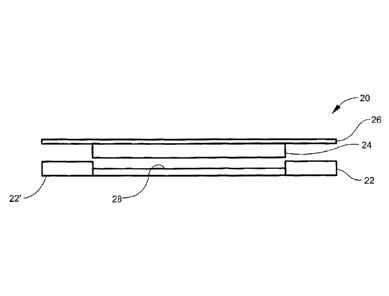
[0031] FIG. 1 schematically depicts a first embodiment of the foam-based
RFID label;
[0032] FIG. 2 is another schematic depiction of the first embodiment of
the foam-based
RFID label;
[0033] FIG. 3 schematically depicts a second embodiment of the foam-based
RFID label;
[0034] FIG. 4 depicts a tire mold and an insert positioned therein for
forming a recess in a
tire sidewall for subsequent affixing of a foam-based RFID label therein;
[0035] FIGs. 5A, 5B, and 5C sequentially depict providing a tire with a
recess (FIG. 5A),
inserting the foam-based RFID label within the recess and affixing the label
to the tire (FIG. 5B),
and subsequently concealing the affixed foam-based RFID label within the tire
with a concealing
composition (FIG. 5C);
[0036] FIG. 6 depicts a tire having a foam-based RFID label affixed to a
recess formed
with a tire sidewall; and
[0037] FIG. 7 depicts a tire having a foam-based RFID label affixed to an
outermost
surface of a tire sidewall without a recess being formed on the tire.
8
CA 3032445 2019-02-01
DETAILED DESCRIPTION
[0038] The present invention will now be described more fully hereinafter
with reference
to the accompanying drawings in which exemplary embodiments of the invention
are shown.
However, the invention may be embodied in many different forms and should not
be construed as
limited to the representative embodiments set forth herein. The exemplary
embodiments are
provided so that this disclosure will be both thorough and complete, and will
fully convey the
scope of the invention and enable one of ordinary skill in the art to make,
use and practice the
invention. Like reference numbers refer to like elements throughout the
various drawings.
[0039] RFID labels according to the present invention enable various tire
tracking
solutions that include electronic identification provisions such as, for
example, RFID devices
incorporated in/onto a foam substrate(s)/layer(s) such that the labels are
configured to withstand
temperatures and stresses associated with a wide variety of tire uses.
[0040] The foam-based RFID label can be affixed to and/or incorporated on
the sidewall
of a wide array of tires. Depending on the type of tire, the stretch of the
tire (sidewall) or the use
of the tire (e.g. racing tires), the thickness of the foam substrate may vary.
For example, the
thicker the tire sidewall, the lesser the stress and thinner the foam
substrate may be.
[0041] As will be appreciated, tires are typically used in combination
with rims of a
vehicle. The rubber-based tire provides support and gripping for the vehicle
with a road or
ground surface. The foam-based RFID label may be used with bias tires, belted
bias tires, radial
tires, solid tires, semi-pneumatic tires, pneumatic tires, airless tires,
truck and bus tires, airplane
tires, agro tires, racing tires, mining tires, etc.
[0042] In certain embodiments the foam-based RFID label can withstand
conditions/stresses typically associated with the environment of the article
(tire) encountered
throughout its lifetime. The articles disclosed herein constantly flex,
expand, contract, and/or are
constantly exposed to other external factors xtemal factors such as debris,
bumps, water/rain,
9
CA 3032445 2019-02-01
snow, and/or ice and can withstand these throughout the lifetime of its
attachment to the tire.
[0043] As discussed further below, the foam-based RFID label generally
includes at least
one RFID device. The at least one RFID device generally includes an antenna
for wirelessly
transmitting and/or receiving RF signals and analog and/or digital electronics
operatively
connected thereto. The RFID device can include passive RFID devices, or active
or semi-passive
RFID devices including a battery or other power source. The electronics can be
implemented via
an integrated circuit (IC) or microchip or other suitable electronic circuit
and inlay include, for
example, communications electronics, data memory, control logic, etc.
[0044] The RFID device can operate in a variety of frequency ranges
including, but not
limited to, a low frequency (LF) range (i.e., from approximately 30 kHz to
approximately 300
kHz), a high frequency (HF) range (i.e., from approximately 3 MHz to
approximately 30 MHz)
and an ultra-high frequency (UHF) range (i.e., from approximately 300 MHz to
approximately 3
GHz). A passive device can operate in any one of the aforementioned frequency
ranges. In
particular, for passive devices, LF systems can operate at about 124 kHz, 125
kHz or 135 kHz,
HF systems can operate at about 13.56 MHz, and UHF systems can use a band from
8601MHz to
960MHz. Alternately, passive device systems can use 2.45 GHz and other areas
of the radio
spectrum. Active RFID devices can operate at about 455 MHz, 2.45 GHz, or 5.8
GHz. Semi-
passive devices can operate at a frequency of about 2.4 GHz.
[0045] The read range of the RFID device (i.e., the range at which the
RFID reader can
communicate with the RFID device) can be determined by the type of device
(i.e., active,
passive, etc). Passive LF RFID devices (also referred to as LFID or LowFID
devices) can
typically be read from within approximately 12 inches (0.33 meters); passive
HF RFID devices
(also referred to as HFID or HighFID devices) can typically be read from up to
approximately 3
feet (1 meter); and passive UHF RFID devices (also referred to as UHFID
devices) can typically
be read from approximately 10 feet (3.05 lneters) or more. One factor
influencing the read range
for passive RFID devices is the method used to transmit data from the device
to the reader, i.e.,
CA 3032445 2019-02-01
the coupling mode between the device and the reader - which can be either
inductive coupling or
radiative/propagation coupling. Passive LFID devices and passive HFID devices
can use
inductive coupling between the device and the reader, whereas passive UHFID
devices can use
radiative or propagation coupling between the device and the reader.
[0046] Alternatively, in radiative or propagation coupling applications
(e.g., as are
conventionally used by passive UHFID devices), rather than forming an
electromagnetic field
between the respective antennas of the reader and device, the reader can emit
electromagnetic
energy that illuminates the device. In turn, the device gathers the energy
from the reader via an
antenna, and the device's IC or microchip uses the gathered energy to change
the load on the
device antenna and reflect back an altered signal, i.e., backscatter. UHFID
devices can
communicate data in a variety of different ways, e.g., increase the amplitude
of the reflected
wave sent back to the reader (i e., amplitude shift keying), shift the
reflected wave out of the
phase received wave (i.e., phase shift keying), or change the frequency of the
reflected wave (i.e.,
frequency shift keying). The reader in turn picks up the backscattered signal
and converts the
altered wave into data understood by the reader or adjunct computer. \
[0047] The antenna employed in the RFID device can be affected by numerous
factors,
e.g., the intended application, the type of device (i.e., active, passive,
semi-active, etc.), the
desired read range, the device-to-reader coupling mode, the frequency of
operation of the device,
etc. For example, insomuch as passive LFID devices are normally inductively
coupled with the
reader, and because the voltage induced in the device antenna is proportional
to the operating
frequency of the device, passive LFID devices can be provisioned with a coil
antenna having
many turns in order to produce enough voltage to operate the device IC or
microchip.
Comparatively, a conventional HFID passive device can be provisioned with an
antenna which is
a planar spiral (e.g., with 5 to 7 turns over a credit-card-sized form
factor), to provide read ranges
on the order of tens of centimeters. HFID antenna coils can be less costly to
produce (e.g.,
compared to LFID antenna coils), since they can be made using techniques
relatively less
expensive than wire winding, e.g, lithography or the like. UHFID passive
devices can be
11
CA 3032445 2019-02-01
radiatively and/or propagationally coupled with the reader antenna and
consequently can employ
conventional dipole-like antennas.
[0048] The foam-based RFID label of the present invention can utilize any
of the
aforementioned RFID devices, as well as others not specifically mentioned. In
one embodiment,
the RFID device is a passive or active device.
[0049] The foam-based RFID label according to the invention can be
installed during tire
manufacture (after vulcanization) such that the label becomes as integral,
inseparable part of the
tire. It should be noted that the phrases "during manufacture" and "during
tire manufacture" as
used herein specifically refer to any processes occurring post-vulcanization
of the tire. In the
event that the foam-based RFID label becomes inoperable, breaks or otherwise
fails, the existing
label can be removed (e.g., by milling out the old label) and inserting a new
label into the
existing recess of the article/vulcanized tire.
[0050] The foam-based RFID label can also be affixed to and/or
incorporated within a
wide array of tires. As discussed in detail below, the label can be
incorporated into the sidewall
to facilitate reading from alongside the tire as well as avoid damage impact
damage.
[0051] The foam-based RFID label is suitable for use with other articles,
including other
rubber-based and non-rubber-based articles. Non-limiting examples of other
rubber-based
articles include suspension components, cushions, shoe soles, hoses, hockey
pucks, conveyor
belts, musical mouth pieces, bowling balls, rubber mats, jewelry molds, etc.,
and may be affixed
to these articles using the installation methods further disclosed herein.
[0052] FIGs. 6 and 7 depict the foam-based RFID labels 20, 120 disclosed
herein affixed
to a tire 300. FIG. 6 specifically depicts a tire 300 having an outer sidewall
301 and an inner
sidewall (not shown) opposite the outer sidewall. A recess 302 is formed on
the outer sidewall
302 between the tire tread 33 and the portion of the tire immediately adjacent
the tire rim with
12
CA 3032445 2019-02-01
one of the foam-based RFID labels 20, 120 being permanently affixed within the
recess and
substantially flush or slightly depressed relative to other portions 305, 306,
307, 308 of the
sidewall immediately adjacent recess 302. In certain aspects and instead of
forming a recess on
the tire sidewall, FIG. 7 depicts one of the foam-based RFID labels 20, 120
directly and
permanently affixed to (on top of) a tire wall 301 such that the foam-based
RFID label protrudes
above and/or extends beyond an outermost surface of the sidewall 301.
[0053] Referring to FIGs. 1-3, various examples of the foam-based RFID
labels are
shownat reference numerals 20, 120, and each generally include an RFID device
24 disposed,
encased, or sandwiched between one or more foam substrate(s) 22 and a face 26
material. The
RFID device, such as a passive RFID device, generally includes an antenna and
an IC.
[0054] Referring to FIGS. 1 and 2, the foam-based RFID label 20 includes a
foam
substrate layer 22, an RFID device 24, and a face layer 26. The RFID device 24
is disposed
between/intermediate the foam substrate layer 22 (also referred to as a "foam
layer", the foam
layer, or the first foam layer herein) and the face layer 26. In a particular
embodiment, the foam
substrate layer 22 includes open cell foam such as reticulated foam,
polyalklylene foam (e.g.,
either a polyethylene foam or polypropylene foam), polyurethane foam or open
cell rubber, all of
which are resiliently deformable and flexible allowing the RFID label to
easily expand and
contract when affixed to a tire without the label being torn and/or damaged
and while
concurrently maintaining operability of the RFID device disposed within the
label such that the
RFID device may communicate with an RFID reader identifying and sensing
conditions of the
article/vulcanized tire throughout the life of the article vulcanized tire.
The foam substrate layer
22 can also include closed cell foam or at least one layer of open cell foam
and/or closed cell
foam in any layer arrangement. The foam substrate layer 22 can be in direct
physical contact and
adhesively bonded to the face layer 26. In one embodiment, the RFID device 24
encompasses
less than the total surface area of the foam substrate layer 22 and the
portion of the foam
substrate layer 22 "outside of' or surrounding the RFID device 24 is
adhesively bonded to the
face layer 26. The face layer 26 can have a larger surface area than the foam
substrate layer 22
13
CA 3032445 2019-02-01
such that portions of the face layer 26 overhang the underlying foam substrate
layer 26. In certain
aspects the face layer 26 comprises a planar layer of polyester and the RFID
device 24 may
further include a polyester planar substrate having an antenna and IC
positioned therein.
Although, the face layer 26 and RFID device 24 may include polyesters that
each aid in
maintaining operability and readability of the RFID device, it should be
further noted that the
polyester comprising the face layer 26 (regardless of overall layer thickness)
is preferably more
rigid and stronger than the polyester included in the RFID device to further
protect and support
the exterior of the label to prevent and/or reduce the likelihood of damage to
the RFID device
from external, physical stress(es). For example, the polyester of the face
layer 26 may be a
thermoforming type of polyester typically used in tire cord while the
polyester included RFID
device may be chosen from a staple fiber or non-woven type of polyester.
Polyester used within
the RFID device is an excellent insulator due to its low outgassing rate and
further aids in
insulating and protecting the RFID capabilities of the RFID device. The face
layer 26 and foam
substrate layer 22 are bonded/adhered to one another. In certain aspects and
in view of FIGs. 1,
2, 6, and 7, the outermost surface of foam substrate layer 22 further includes
an adhesive and/or
surface treatment 22' such that the label 20 may be affixed directly within a
recess 302 formed on
the tire sidewall 301 or directly on tire sidewall 301. As shown in FIG. 2,
the RFID device 24
may be positioned within a recess 28 formed in the foam substrate layer 22.
[0055] The foam-based RFID label 20 is preferably configured to be
permanently affixed
to the tire or other article. The terms "affix" or "affixed" as used herein
refers to attaching,
adhering or incorporating the label to or within or on an outer surface of the
article. Affixed also
includes embedding the label within the article such only the face layer 26 is
visible on the
finished article. For example, as shown in FIG. 6 and as previously discussed
above, the label 20,
120 is disposed on the tire such that the face layer 26 is aligned flush with
or slightly depressed
relative to the tire sidewall 302.
[0056] FIG. 3 depicts another foam-based RFID label 120 contemplated herein
that
includes the face layer 26 (e.g., made from and/or including polyester as
discussed above in view
14
CA 3032445 2019-02-01
of FIGs. 1 and 2), the RFID device 24, and a first foam substrate layer 22
(first foam layer). With
regard to the RFID device 24, FIG. 3 further depicts the antenna and IC 24'
positioned on a
planar substrate 24" (also referred to as polyester planar substrate as
previously discussed above
in view of FIGs. 1 and 2) that is preferably made from and/or includes
polyester with the RFID
device configured to maintain operability between 300 MHz to 3 GHz to identify
and/or sense
conditions of a vulcanized tire and further communicates the same to an RFID
reader when
within a predetermined proximity of the RFID reader, and the face layer 26
formed of a
polyester planar substrate that is more rigid than the polyester planar
substrate of the RFID
device. As further depicted in FIG. 3, the foam-based RFID label 120 further
includes a first
adhesive layer 121 between the face layer 26 and foam layer 22 that adhere the
face layer 26 and
foam layer 22 to one another and further encase the RFID device 24 therein.
The foam-based
RFID label 120 of FIG. 3 further includes a second foam layer 122 adhered to
the foam layer 22
(first foam layer) by a second adhesive layer (e.g., 22') disposed between the
two foam layers. In
certain aspects, the second adhesive layer (not shown) is an adhesive coating
that coats an outer
surface of either the foam layer 22 or second foam layer 122, thus allowing
foam layer and
second foam layer 122 to be adhered to one another. A rubber adhesion layer
coating 122' is
further included on an outer surface of the second foam layer 122 that is
opposite the second
adhesive layer, the rubber adhesion layer is configured to adhere and
permanently affix the foam-
based RFID label to the vulcanized tire. The foam-based RFID label 120 further
includes a
removable liner 126 configured to be removed from the foam-based RFID label
120 before
affixing the foam-based RFID label to the vulcanized tire. In certain aspects,
each layer included
within the labels 20, 120 of FIGs. 1-3 are substantially planar. Furthermore
each foam layer
disclosed herein may be a foam tape having a single-sided or double-sided
adhesive applied
thereon to adhere various layers of the labels 20, 120 as disclosed above.
[0057] In view of the above disclosures, FIGs. 5A-5C sequentially depict
methods of
installing and using the foam-based RFID label(s) 20, 120 in or on a sidewall
301 of a vulcanized
tire 300. As shown in FIG. 5A, the method includes forming either during
vulcanization or post-
vulcanization a recess 302 having a predetermined shape on an outermost or
innermost surface of
CA 3032445 2019-02-01
the tire (e.g., an outer sidewall 301 or an inner side wall (not shown) of
tire 300). Next, at least
one of the foam-based RFID labels 20, 120 that is configured to identify the
tire and/or to sense
conditions of the tire and communicate the same to an RFID reader when within
a predetermined
proximity of the RFID reader is provided. As further shown in FIG. 5B, the
foam-based RFID
labels 20, 120 are subsequently affixed within the recess 302 of the
vulcanized tire 300 by
contacting and adhering an adhesive surface of the foam-based RFID label to a
surface of the
recess 302 to subsequently identify the tire and/or sense conditions of the
tire.
[0058] As further depicted in FIGs. 4, 5A, 5B, and 6, in certain aspects,
the recess is
formed during vulcanization by molding a predetermined shape within an
outermost surface of a
sidewall 302 of the tire. Referring specifically to FIG. 4, a tire mold 200
for molding and
vulcanizing a "green", unvulcanized tire may be provided. Within the mold 200
of FIG. 4, plate
201 is further provided to form recess having a predetermined shape in tire
sidewall 301 as
shown for example in FIGs. 5B and 6. As shown in FIG. 5B, in certain aspects,
the recess 302 is
defined by/formed by a base, a plurality of connected sidewalls, and an
opening formed opposite
the base such that the recess has dimensions slightly larger than the label
20, 120 so that the label
may be placed therein and affixed to the tire such that gaps/clearance exists
between the
sidewalls of the recess and the sides of the label. In other alternative
aspects, the recess 302 is
formed by milling an outermost surface of the tire into a predetermined shape,
the recess formed
by milling also having a base, a plurality of connected sidewalls, and an
opening formed opposite
the base that form a predetermined shape with the milled recess having
dimensions slightly larger
than the label 20, 120 so that the label may be placed therein and affixed to
the tire.
[0059] As further shown in FIGs. 5B and 6, the adhesive surface of the
foam-based RFID
label is adhered to the base of the recess and completely positioned within
the recess such that
the face layer of the RFID device is either flush with or slightly depressed
relative to other
outermost surfaces 305, 306, 307, 308 of the sidewall that are immediately
adjacent the recess.
In certain aspects, the RFID device is flush with the other outermost surfaces
of the sidewall of
the tire. In certain aspects, RFID device is slightly depressed relative to
other outermost surfaces
16
CA 3032445 2019-02-01
of the sidewall of the tire
[0060] As further shown in FIGs. 5B and 5C, in certain aspects, it may be
aesthetically
desirable to conceal the RFID label within the tire. In this aspect and as
further shown in FIG.
5C, a concealing composition 50 (e.g., an epoxy resin mixed with a colorant
that matches the
color of the article/tire or a rubber based resin ¨ either a "green" rubber
based resin or a curable
rubber based resin) may be applied over the foam based RFID label to conceal
and further encase
the face layer of the foam based RFID label, as well as the all portions of
the RFID label, within
the tire. In each of the aspects discussed above, the RFID device preferably
maintains RFID
operability between 300 MHz to 3 GHz and identifies and/or senses conditions
of the tire and
further communicates the same to an RFID reader when within the predetermined
proximity of
the RFID reader.
[0061] The inventive concepts disclosed herein are further directed to
methods of
identifying a rubber-based article (e.g., tires post-vulcanization). The
methods can include
affixing one or more foam-based RFID labels to a rubber-based article, the
label including an
RFID component configured to provide a unique identifier or other information
upon being read
or otherwise interrogated. Once the label is affixed to the rubber-based
article, the unique
identifier is thus associated with that particular article. As further
disclosed herein, in certain
aspects, the inventive concepts further include a vulcanized tire having at
least one of the
disclosed foam-based RFID labels affixed thereon (e.g., within a recess of the
tire sidewall or
directly on top of the tire sidewall).
[0062] The article can be identified by use of an RFID reader as
previously described
herein. Identification of the article enables a wide array of applications to
be performed such as
tracking the article in a manufacturing or production system, monitoring the
location of the
article, performing inventory operations, etc.
[0063] The foregoing description provides embodiments of the invention by
way of
17
CA 3032445 2019-02-01
example only. It is envisioned that other embodiments may perform similar
functions and/or
achieve similar results. Any and all such equivalent embodiments and examples
are within the
scope of the present invention and are intended to be covered by the appended
claims.
18
CA 3032445 2019-02-01