Note: Descriptions are shown in the official language in which they were submitted.
1
RECESSED-MAGNET FLYWHEEL CONSTRUCTION FOR VERTICAL AXIS WIND
TURBINES
FIELD OF THE INVENTION
The present invention relates generally to wind turbines, and more
particularly to axial-flux generators of vertical axis wind turbines in which
permanent
magnets are recessed into the rotor of the generator.
BACKGROUND OF THE INVENTION
It is well known for a vertical axis wind turbine (VAVVT) to employ an
axial-flux generator in which a series of permanent magnets circumferentially
disposed around the central rotational axis of the rotor flywheel are situated
with
their poles facing axially toward a stator whose coils are likewise disposed
around
the same axis. The stator-facing poles of the permanent magnets alternate
between
North and South moving sequentially from one magnet to the next around the
central
axis. The rotor is driven for rotation about the central axis under the effect
of wind
currents acting on blades or foils coupled to the rotor, and the movement of
the
alternating stator-facing magnetic poles past the coils in close axial
proximity thereto
generates current in the coils.
An example of such a VAVVT generator is disclosed in PCT Application
Publication No. W02011/113143. This reference employs a surface-mounted
configuration of the magnets on the rotor flywheel, in which the permanent
magnets
are bonded to a flat face of the flywheel using suitable adhesive.
However, a potential risk with adhesive surface mounting is that the
adhesive bond will not hold up against centrifugal forces acting radially
outward
during rotation of the flywheel, introducing the risk of the magnets shearing
off the
face of the flywheel and being ejected outward from the perimeter edge
thereof.
One prior solution to better secure the permanent magnets in place is
shown in U.S. Patent Application Publication No. U52010/0194251 in which a
rotor
plate of magnetically attractive material provides a base to which the
permanent
magnets are magnetically secured, and a separate magnet index ring with
cutouts of
magnet conforming shape is adhesively secured to the rotor base plate to
positively
Date Recue/Date Received 2022-02-14
2
position the magnets according to the layout of the cutouts and to block
shifting of
the magnets along the face of the rotor base plate.
However, such a solution increases the number of separate
components in the rotor assembly by relying on a dedicated piece to retain the
magnets in place. While reliance on the index or retaining ring to determine
the
proper magnet positions eliminates the need to position with magnets with a
suitable
jig during production, the ring itself must be carefully installed and
precisely located
in order to ensure the proper final magnet positions.
Accordingly, there remains room for improved or alternate magnet-
mounting solutions for VAVVT generators.
Other references disclosing mounting of permanent magnets on rotors
of various rotational machines and devices include the following EP1014542,
J P2005094955, J P2007104820, US3762042, US4318019,
US5982070,
US6798103, US6891295, US6952058, US7145276, US7279819, US7973443,
US2005/0127767, US2007/0247017, US2010/0148516, US2010/0187934,
US2012/0286520, and US2013/0090203.
SUMMARY OF THE INVENTION
According to a first aspect of the invention there is provided a rotor for
a vertical axis wind turbine, the rotor comprising:
a flywheel having first and second faces located opposite one another
across a thickness of the flywheel so as to face opposite directions along a
central
axis passing through said first and second faces, and a circumferential
perimeter
edge joining the first and second faces together around the central axis at a
perimeter of the flywheel; and
a series of cavities spaced radially inward from the circumferential
perimeter edge and opening into the flywheel from the first face thereof on a
path
disposed circumferentially about the central axis to carry a series of
permanent
magnets in the series of cavities with poles of said magnets facing in an
axial
direction along the central axis.
Date Recue/Date Received 2022-02-14
3
According to a second aspect of the invention there is provided a rotor
for a vertical axis wind turbine, the rotor comprising:
a flywheel having first and second faces located opposite one another
across a thickness of the flywheel so as to face opposite directions along a
central
axis passing through said first and second faces, and a circumferential
perimeter
edge joining the first and second faces together around the central axis at a
perimeter of the flywheel; and
a series of cavities spaced radially inward from the circumferential
perimeter edge and opening into the flywheel from the first face thereof on a
path
disposed circumferentially about the central axis; and
a series of permanent magnets each seated within a respective one of
the series of cavities with poles of said magnets facing in an axial direction
along the
central axis.
In one embodiment, the series of permanent magnets are arranged in
adjacent pairs around the central axis with a north pole of one magnet in each
pair
and a south pole of another magnet in each pair facing a same axial direction
along
the central axis as the first face of the flywheel.
Preferably the magnets are positioned within the cavities in partially
recessed positions reaching outwardly beyond the first face of the rotor from
within
the cavities.
Preferably the magnets have a thickness exceeding a depth of the
cavities and the magnets reach axially outward of the cavities past the first
face of
the flywheel.
Preferably each cavity receives only a single magnet therein.
Preferably each magnet is adhesively secured in the respective cavity.
Preferably each cavity contains only part or all of the respective
magnet and adhesive securing said respective magnet in place in the cavity.
Each magnet may have a trapezoidal shape in planes normal the
central axis, with a shorter one of two parallel sides of the trapezoidal
shape of each
Date Recue/Date Received 2022-02-14
4
magnet located nearer to the central axis than an opposing longer one of said
two
parallel sides of the trapezoidal shape of each magnet.
In such instance, each cavity preferably has a trapezoidal shape in
planes normal the central axis, with a shorter one of two parallel sides of
the
trapezoidal shape of each cavity located nearer to the central axis than an
opposing
longer one of said two parallel sides of the trapezoidal shape of each cavity.
Alternatively, each magnet may have an arcuate shape in planes
normal the central axis, with a shorter one of two concentrically arcuate
edges of the
arcuate shape located nearer to the central axis than an opposing longer one
of said
concentrically arcuate edges of the trapezoidal shape.
In such instance, each cavity preferably has an arcuate shape in
planes normal the central axis, with a shorter one of two concentrically
arcuate
edges of the arcuate shape of each cavity located nearer to the central axis
than an
opposing longer one of said two concentrically arcuate edges of the arcuate
shape
of each cavity.
Preferably the cavities are pocket-shaped cavities recessed into the
flywheel from the first face thereof and terminating short of the second face
for
seating of the magnets against bottom surfaces of the pocket-shaped cavities
disposed intermediately between the first and second faces of the flywheel.
Preferably the thickness of the flywheel is at a maximum at the
circumferential perimeter edge thereof to define a full-thickness
circumferential
region of the flywheel between the series of cavities and the circumferential
perimeter edge.
Preferably the series of cavities are separated from one another
around the central axis by intact regions of the flywheel spanning from the
first face
to the second face at locations between the cavities.
Preferably the flywheel is a single unitary body that seamlessly and
integrally defines the first and second faces and all boundary walls of the
cavities
opening into the first face of the flywheel.
Preferably the unitary body is magnetically attractable.
Date Recue/Date Received 2022-02-14
5
Preferably the flywheel is steel.
According to a third aspect of the invention there is provided a vertical
axis wind turbine comprising:
a stator comprising coils carried thereon to reside around a vertical
rotational axis of the wind turbine;
a rotor according to the first or second aspect of the invention, which is
rotatably supported with a central axis of the rotor coincident with the
vertical
rotational for rotation of the rotor therearound and with the first face of
the rotor
facing toward the stator in close proximity thereto to position the north and
south
poles of the magnets near the coils of the stator; and
wind engagement members coupled to the rotor in a manner arranged
to drive rotation of the rotor about the vertical rotational axis under action
of wind
current on the wind engagement members, whereby movement of the poles of the
magnets past the coils induces current therein.
According to a fourth aspect of the invention there is provided a
method of producing a rotor for a vertical axis wind turbine, the method
comprising:
in a flywheel having opposing first and second faces and a
circumferential perimeter edge, machining pocket-shaped cavities into the
flywheel
from the first face thereof at locations inwardly from the circumferential
perimeter
edge thereof for receipt of a respective magnet into each pocket-shaped cavity
in an
installed position in which outwardly radial movement of the magnet toward the
perimeter edge of the flywheel under rotation of the flywheel is blocked by a
perimeter of the cavity.
Preferably the method includes machining the cavities as pocket-
shaped cavities that terminate short of the opposing second face to create a
seat in
each cavity at a plane disposed intermediately between the opposing faces of
the
flywheel for placement of a respective magnet into the pocket-shaped cavity in
a
seated position with one pole of said magnet facing said seat and an opposing
pole
of said magnet facing a same direction of the first face of the flywheel, and
the
flywheel has a unitary body construction of a material composition that
integrally and
Date Recue/Date Received 2022-02-14
6
seamlessly defines the opposing first and second faces and the circumferential
perimeter edge of the flywheel,
BRIEF DESCRIPTION OF THE DRAWINGS
In the accompanying drawings, which illustrate one or more exemplary
embodiments of the present invention:
Figure 1 is an overhead plan view of a rotor flywheel for an axial flux
generator of a vertical axis wind turbine, with recessed pockets in a face of
the
flywheel for mounting of magnets within the same.
Figure 2 is a partial closeup view of the rotor flywheel of Figure 1 as
marked at detail circle A thereof.
Figure 3 is an edge-on view of the rotor flywheel of Figure 1.
Figure 4 is partial cross-sectional view of an assembled rotor as taken
along line IV ¨ IV of the rotor flywheel of Figure 2, illustrating seating of
one magnet
of the assembled rotor in a partially recessed position in a machined pocket
of the
flywheel.
Figure 5 is partial plan view of another assembled rotor, which differs
from that in Figure 4 only in that the recessed pockets and the magnets seated
therein are trapezoidal, rather than rectangular, in shape.
Figure 6 is partial plan view of yet another assembled rotor, which
differs from those of Figures 4 and 5 only in that the recessed pockets and
the
magnets seated therein are arc-shaped.
Figure 7 is a schematic perspective elevational view of a vertical axis
wind turbine that may employ the inventive rotor flywheel of the present
invention.
DETAILED DESCRIPTION
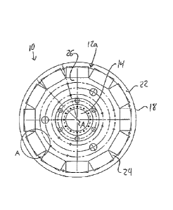
Figure 1 shows a flywheel 10 for a rotor of an axial flux generator for a
vertical axis wind turbine. The figure shows a plan view of the rotor from a
first face
12a thereof that faces toward the stator of the generator during use.
In a
conventional manner, the flywheel 10 is of a plate-shaped annular form of
circular
inner and outer peripheries, whereby a central opening 14 passing axially
through
the flywheel accommodates receipt of a vertically standing spindle
therethrough for
Date Recue/Date Received 2022-02-14
7
rotatable support of the flywheel on the spindle by a suitable bearing (not
shown). In
a known manner, the flywheel is thus configured with suitable mounting
features
around the central opening therein for mounting of a bearing on the flywheel
to
enable relative rotation between the flywheel and the spindle (not shown).
As known in the art, the flywheel may have its first face oriented
upward or downward toward the stator, depending on whether the rotor in
question
is mounted over or beneath the stator. A flywheel of the described type may be
employed for one or both rotors in a two-rotor generator in which a pair of
rotors are
respectively disposed above and below the stator. Likewise, a flywheel rotor
of the
present invention may be employed in a wind turbine having multiple stators
and
rotors. The aforementioned PCT application may be referred to for further
details of
the relative positioning of the rotors and stator and possible mounting
solutions for
same, although other mounting solutions known in the art may likewise be
employed.
Where the flywheel differs from conventional design is in the presence
of a series of pocket-shaped cavities 16 machined into the flywheel at the
first face
12a thereof to a depth reaching partially, and not fully, through the axial
thickness of
the flywheel. Each cavity 16 is thus recessed in the flywheel from the first
face 12a
thereof to extending toward, without reaching, the opposing parallel face 12b
of the
flywheel, which faces away from the stator in the final generator assembly. In
the
first embodiment, the cross-sectional shape of each recess in planes normal to
the
central axis A is rectangular, although other options are also contemplated,
for
example as exemplified by other embodiments referenced herein further below.
Each rectangular cavity has a depth D measured parallel to the central
rotational
axis A of the flywheel, a width W measured radially of the central axis A, and
a
length L measured tangentially of the central axis A at a radius that bisects
the cavity
at the mid-point of this length.
The pocket-shaped cavities are arranged on a circular path around the
central axis A at a radial distance outward therefrom, but inward from the
circumferential perimeter edge 18 that joins the two faces of the flywheel
together
Date Recue/Date Received 2022-02-14
8
around the outer periphery thereof. A thickness T of the flywheel is measured
between the two faces of the flywheel in a direction parallel to the central
axis A at
this circumferential perimeter edge 18. The identically sized and shaped
rectangular
pockets or cavities 16 of the first embodiment each closely conform in cross-
sectional size to a permanent magnet 20 that is to be respectively received in
the
pocket 16 during assembly of the rotor of the VAVVT generator. Accordingly,
mere
placement of each magnet into the respective pocket 16 acts to positively
position
this magnet in its appropriate position so that the series of magnets
occupying the
series of pockets are evenly distributed around the central axis at the same
radial
distance therefrom.
A flat bottom 16a of each pocket 16 lies in a plane parallel to the two
faces of the flywheel 10 at an intermediate location between these faces along
the
axial or thickness direction of the flywheel. The four side walls 16b, 16c,
16d, 16e of
each pocket may each be perpendicular to the plane of the flat bottom thereof
so
that the pocket boundaries defined by the four side walls and closed bottom of
the
pocket cooperate with the imaginary boundary defined by the plane of the
flywheel's
first face 12a o delimit a volume of rectangular cuboid form. As shown in
Figure 3,
the depth D of the pockets may be equal, or approximately equal, to half of
the
overall thickness T of the flywheel 10.
From the circumferential perimeter edge 18 of the flywheel to the
radially outermost one of the two tangential side walls 16c of each pocket, a
circumferential edge-adjacent region 22 of the flywheel 10 is intact over the
full
overall thickness T of the flywheel around the full outer circumference
thereof. This
intact full-thickness region 22 presents a barrier to radially outward
shifting of the
magnet in each pocket by centrifugal forces during rotation of the flywheel in
the final
VAVVT assembly. As best shown in Figure 2, the full flywheel thickness is also
left
intact between each adjacent pair of pockets in the series so that this intact
full-
thickness inter-pocket region 24 between each neighbouring pair of pockets
forms a
physical separation or barrier between the two pockets. Likewise, another full-
thickness region 26 of the flywheel is left intact at the radially innermost
one 16b of
Date Recue/Date Received 2022-02-14
9
the two tangential side walls of each pocket, spanning radially inward
therefrom
toward the bearing-supporting area of the flywheel around the central opening
14
therein.
Accordingly, each and every pocket machined into the flywheel is fully
surrounded on all sides by intact full-thickness areas of the flywheel. The
flywheel,
is formed by a single unitary body of magnetically attractable material that
seamlessly and integrally defines the two opposing flywheel faces of circular
perimeter, the circumferential perimeter edge joining the faces together, and
the
walls and bottom of each recessed pocket-shaped cavity. The flywheel, for
example, may be machined from a piece of ferromagnetic steel stock of uniform
material composition, for example a mild or soft steel such as W44. By
machining
magnet-accommodating pockets into a single-piece flywheel, the number of
pieces
to the overall rotor construction is reduced compared to use of a retaining
ring or
other separate component to define a barrier for blocking centrifugal or other
displacement of the magnets during driven rotation of the rotor by wind
currents
acting on wind engagement surfaces of blades or vanes coupled to the rotor.
Different vane or blade designs defining suitable wind engagement members are
known in the art, as are suitable solutions for coupling the same to the rotor
in
manner driving rotation of the same so as to operate the generator under the
action
of the wind. Accordingly, further details of such components are omitted
herein.
With reference to Figure 4, to assemble the rotor, a respective magnet
20 is lowered into each pocket 16 from the open end thereof at the first face
12a of
the flywheel 10. In a conventional manner, an even number of magnets may be
used and may be oriented such that for each pair of adjacent magnets around
the
flywheel, opposite poles of the two magnets in the pair face outwardly away
from the
first face 12a of the flywheel in the axial direction. That is, the poles of
the magnets
alternate around the flywheel axis A so that the north pole of one magnet in
each
adjacent pair and a south pole of the other magnet in this same pair face a
same
common direction along the central axis as the first face of the flywheel. The
axial
.. direction faced by the poles of each magnet is schematically illustrated by
magnet
Date Recue/Date Received 2022-02-14
10
axis A2 in Figure 4, which can be seen to be parallel to the central axis A of
the
flywheel 10. The alternating poles of the magnets are schematically
illustrated in
Figure 5, where N denotes a magnet's north pole, and S denotes the adjacent
magnet's south pole.
In the illustrated embodiments, the thickness of the magnet 20
(measured parallel to the flywheel thickness T) exceeds the depth D of the
pocket
16. As a result, insertion of the magnet into a seated position resting atop
the flat
bottom 16a of the pocket 16 leaves a portion of the magnet outside the pocket,
so as
to reach axially beyond the first face 12a of the flywheel, and onward toward
the
stator of the VAVVT generator once fully assembled. The magnets of the
illustrated
embodiments are thus partially recessed within the flywheel, as opposing to
being
fully recessed therein. In other embodiments, the magnets may be fully
recessed to
a level flush with, or recessed slightly from, the first face 12a of the
flywheel.
In addition to the magnetic attraction between the permanent magnet
20 and the ferromagnetic flywheel body, the magnet may be adhesively secured
in
place in the respective pocket, for example at least at the face-to-face
interface
between the underside of the magnet and the flat bottom 16a of the pocket.
Testing of prototypes of the invention has revealed that the partially
recessed magnet will exert greater magnetic forces in the axial direction on
the
stator-facing side 12a of the flywheel than are provided by use of the same
magnet
in a conventional surface-mounted application. Accordingly, not only does the
pocket-featuring flywheel reduce the number of components in the final
generator by
avoiding a separate magnet-retention ring or the like, but the recessed
magnets also
improve the performance of the generator. In addition, manual labour in
assembling
the generator can be reduced compared to prior art solutions in which a
retention
ring was manually placed and adhered, as the magnet-retaining pockets of the
present invention can be implemented on an automated basis, for example as
part
of a CNC machining process used to form other machined features of the
flywheel,
such suitable attachment points for the central bearing that carries the
finished rotor
on the spindle of the VAVVT generator.
Date Recue/Date Received 2022-02-14
11
While the first embodiment employs rectangular pockets and magnets,
other embodiments may employ alternate shapes. With reference to Figure 2, the
use of rectangular pockets and magnets results a non-uniform gap G between
each
adjacent pair of pockets, and thus between each adjacent pair of similarly
shaped
.. magnets. That is, the pockets, and thus the conformingly shaped magnets
received
therein, are closest together at the radially innermost sides 16b of the
pockets 16,
and grow further apart moving radially outward toward the circumferential
perimeter
edge 18 of the flywheel. As a result, the gap between the pockets/magnets at
the
radially outermost sides 16c of the pockets is notably greater than at the
innermost
sides 16b.
Figure 5 illustrates the use of trapezoidally shaped recesses 16' and
trapezoidally shaped magnets 20' to leave an inter-pocket flywheel region 24'
of
uniform width so as to provide a uniform gap size between the magnets in the
circumferential direction around the central axis A. The shorter one 116b of
the two
parallel tangentially-oriented sides 116b, 116c of the trapezoidal pocket 116'
lies
nearer the central axis A than the opposing one 116c of these sides that lies
nearer
the circumferential perimeter edge 18 of the flywheel. Each one of the two non-
parallel non-tangential sides 116d, 116e of the trapezoidal pocket 16' lies
parallel to
a matching side of the next pocket, each of which lie parallel to a radius of
the
flywheel that bisects the uniform gap between these two pockets. The sides of
the
trapezoidal magnets are related to one another in the same manner as the sides
of
the pockets of matching shape.
Figure 6 illustrates use of arcuately shaped recesses 16" and arcuately
shaped magnets 20" to likewise leave an inter-pocket flywheel region 24' of
uniform
width so as to provide a uniform gap size between the magnets in the
circumferential
direction around the central axis A. Each pocket, and each correspondingly
shaped
magnet, has two opposing arcuate sides 216b, 216c concentrically curving about
the
central axis A, and two opposite linear sides 216d, 216e that join the arcuate
sides
together at the respective ends thereof. The shorter one 216b of the two
concentric
arcuate sides of the pocket lies nearer the central axis A than the opposing
one 216c
Date Recue/Date Received 2022-02-14
12
of these edges that lies nearer the circumferential perimeter edge 18 of the
flywheel.
Each one of the two linear sides of the arcuate pocket 16' lies parallel to a
matching
side of the next pocket, each of which lie parallel to a radius of the
flywheel that
bisects the uniform gap between these two pockets. The sides of the arc-shaped
magnets are related to one another in the same manner as the sides of the
pockets
of matching shape.
Figure 7 illustrates an example of a vertical axis wind turbine 100
which may employ the forgoing rotor structure in its generator. The wind
turbine 100
features a vertically upright central pole 102, to which a stator 104 is
attached or
affixed in a stationary position centered on the axis of the pole 102. A rotor
106 of
the type disclosed herein above is carried on the pole in a position centered
on the
axis thereof and rotatable about said axis, with the first side of the rotor
facing
toward the stator to place the recessed magnets in close proximity to the
coils of the
stator. A plurality of blades 108 are coupled to the rotor 104 to engage the
wind and
thereby provide a drive source in the rotor, rotation of which induces current
in the
stator. It will be appreciate that various VAVVT designs employing this same
general
configuration of parts may likewise exploit the benefits of the inventive
rotor of the
present invention.
While the illustrated embodiment has an even number of magnets
arranged around the central axis with their poles alternating from one to the
next (i.e.
with the north pole of one magnet facing the same axial direction as the south
pole
of the next magnet), it will be appreciate that other embodiments may depart
from
such a configuration and instead have the magnets all facing a common
direction.
Since various modifications can be made in my invention as herein
above described, and many apparently widely different embodiments of same made
within the scope of the claims without departure from such scope, it is
intended that
all matter contained in the accompanying specification shall be interpreted as
illustrative only and not in a limiting sense.
Date Recue/Date Received 2022-02-14