Note: Descriptions are shown in the official language in which they were submitted.
CA 03032619 2019-01-31
WO 2017/024066
PCT/US2016/045412
1
1 TITLE
2 COMPUTERIZED TRAINING PUNCHING BAG
3 BACKGROUND OF THE INVENTION
4
1. Field of the Invention
6 This invention relates to an improved punching bag that can
7 be used to train boxers or to perform a new form of exercise
8 workout.
9
Boxing is a sport that requires lots of practice in order
11 to achieve proper accuracy and force. If there is a device
12 which can measure the performance of a boxer, then boxers will
13 understand their movements and will be helped in improving their
14 boxing skill.
16 2. The Prior Art
17 A known punching bag is shown in FIG. 1A and has no
18 electronics to communicate with the boxer or to give feedback
19 about the training or punching performance. An exercise
ProStrike@ Free Standing Heavy Punch Bag shown in FIG. 1G and a
21 training shield to be punched shown in FIG. 1F have similar
22 deficiencies. A Sporteq@ bob dummy is shown in FIG. 1B and has
23 no electronics. A training device shown in FIG. 1C has no
CA 03032619 2019-01-31
WO 2017/024066
PCT/US2016/045412
2
1 display screen. Devices shown in FIGS. 1D, 1H, 11, and IJ have
2 simple electronics and are battery-powered and do not have
3 continuous display screens. The Eastpoint Sports Majik@ Jab and
4 Bob is shown in FIG. 1H. The Franklin Sports Go Pro MMA
Inflatable Hitting Bag is shown in FIG. 11. The Amber Sports
6 Slam Man shown in FIG. 1J must be filled with sand if the
7 device is to have stability. The Nexersys@ cardio boxing
8 exercise equipment shown in FIG. 1E provides increased
9 communication with the exerciser/trainee but the flat screen
projects forwards and the exerciser/trainee stands in the same
11 spot throughout the training.
12
13 Accordingly, a need exists for an improved punching device
14 which provides enhanced communication with a trainee, improved
tracking of training performance, increased variety in prompting
16 trainee movement, and increased engagement of the intelligence
17 of the trainee as the training is undertaken.
18
19
SUMMARY OF THE INVENTION
21
CA 03032619 2019-01-31
WO 2017/024066
PCT/US2016/045412
3
1 An electronic punching bag is provided that includes an
2 elongate bag, a microprocessor, and a display screen. The
3 elongate bag is formed of resilient material. The
4 microprocessor is disposed in an interior of the electronic
punching bag or at a periphery of the electronic punching bag.
6 The display screen extends around more than half of the
7 periphery of the electronic punching bag and is configured to
8 receive signals from the microprocessor. The signals cause the
9 display screen to display visual signals.
11
12 BRIEF DESCRIPTION OF THE DRAWINGS
13 Other objects and features of the present invention will
14 become apparent from the following detailed description
considered in connection with the accompanying drawings. It
16 should be understood, however, that the drawings are designed
17 for the purpose of illustration only and not as a definition of
18 the limits of the invention.
19
In the drawings, similar reference characters denote
21 similar elements throughout the several views.
22
CA 03032619 2019-01-31
WO 2017/024066
PCT/US2016/045412
4
1 FIGS. 1A-1J show views of the prior art training devices as
2 described above.
3
4 FIG. 2 is a perspective view of one embodiment of the
electronic punching bag according to the invention.
6
7 FIG. 3A shows a perspective view of an embodiment of an
8 electronic punching bag according to the invention, FIG. 3B
9 shows a cross-section through the electronic punching bag of
FIG. 3A in which sensors are visible embedded in the bag, and
11 FIG. 3C shows a view of resilient material in which sensors are
12 embedded before it is manufactured into part of a punching bag.
13
14 FIG. 4A is a perspective view of a lower portion of a
further embodiment of the electronic punching bag with a frame
16 cage protective device. FIG. 4B shows the bag of FIG. 4A being
17 suspended from the floor.
18
19 FIG. 5A is a perspective view of a lower portion of another
embodiment of the electronic punching bag with a soft pad
21 protective device. FIG. 5B shows the bag of FIG. 5A being
22 suspended from the floor.
CA 03032619 2019-01-31
WO 2017/024066
PCT/US2016/045412
1
2 FIG. 6A is a perspective view of a lower portion of another
3 embodiment of the electronic punching bag with an air bag
4 protective device. FIG. 6B shows the bag of FIG. 6A being
5 suspended from the floor.
6
7 FIGS. 7A-7D show perspective views of different embodiments
8 of the target symbols disposed on the electronic punching bag.
9
FIGS. 8A and 8B show perspective views of alternative
11 embodiments of the electronic punching bag.
12
13 FIGS. 9 and 10 show two different electrical system
14 architecture embodiments for the electronic punching bag.
16 DETAILED DESCRIPTION OF THE PREFERRED EMBODIMENTS
17 In any sport, especially contact sports, the ability to
18 react on impulse is ideal.
19
Using a digitally-timed lighting system, the electronic
21 punching bag described herein improves impulsive reactions and a
22 host of other dynamic movements of the boxer/athlete who trains
CA 03032619 2019-01-31
WO 2017/024066
PCT/US2016/045412
6
1 with it. The boxer/athlete is trained to improve his or her
2 visual perception and thought processing in relation to
3 coordinated movements. The pattern and target symbol challenge
4 the spatial intelligence and visual awareness of the boxer. The
articulation between visual recognition, comprehension, and
6 mobility skills is challenged.
7
8 The device mainly uses non-verbal communication.
9 Physical responses are tracked to provide a solid scale for
software to analyze speed improvements and performance. The
11 bag tracks improvement of the boxer. Tracking the reaction time
12 is an optional feature that allows an acceptable delay to be set
13 and can be controlled by the user for a particular level of
14 difficulty. The task will only be considered accomplished and
posted on a performance review if it is completed within the set
16 time.
17
18 Neuro-transmission occurs instantaneously with thought.
19 Millions of electrical impulses convert dormant motor neurons to
action potentials. Action potentials are electrical pulses that
21 travel neuron to neuron to form nerve networks that link brain
22 to muscle neural activity. The pulses conduct and transfer
CA 03032619 2019-01-31
WO 2017/024066
PCT/US2016/045412
7
1 information from brain to muscle at electrifying speeds. All
2 movements in regards to graded force, motion speed, or precision
3 are direct responses to the recruitment and transmission of
4 action potentials.
6 Can we only move as fast as we think? For instance if
7 someone unexpectedly took a swing at two people, and one person
8 flinched but the other ducked, we see two different reactions to
9 the same stimulus. Nevertheless, both subjects reacted before
thinking. Studies have shown that humans have reflex pathways
11 that entirely circumvent our brain. They are amongst the
12 quickest response mechanisms. But can these mechanisms be
13 trained and why did the one person flinch and the other duck?
14 Perhaps the person who ducked had his muscle memory trained from
some physical activity in the past or perhaps the person who
16 ducked perceives visual information faster than the other
17 person.
18
19 Without seeking to answer these questions conclusively, the
electronic punching bag described herein helps train muscle
21 memory by inducing repeated physical activity and by testing the
22 boxer to continue to think and process visual information even
CA 03032619 2019-01-31
WO 2017/024066
PCT/US2016/045412
8
1 when he or she is tired. The precision bag flashes tasks with
2 light, because light has a high speed of travel like electrical
3 energy has.
4
The electronic punching bag also is useful in the field of
6 rehabilitative work for those individuals who have acquired
7 brain injuries such as through a stroke or trauma or in
8 countering brain degenerative diseases such as Parkinson's
9 Disease. It is now generally accepted that acquired brain
injuries, such as occur in stroke or trauma, initiate a cascade
11 of regenerative events that last for up to several weeks if not
12 months. Many investigators have pointed out striking parallels
13 between post-injury plasticity and the molecular and cellular
14 events that take place during normal brain development.
Behavioral experience is the most potent modulator of brain
16 plasticity. Based on the quantity and quality of motor
17 experience, the brain can be reshaped after injury in either
18 adaptive ways. Boxing develops physical strength, breath
19 control, and helps teach an individual to stay focused under
stress. These benefits of boxing all just happen to be the
21 stimulants needed for neuro-plasticity to kick in.
22
CA 03032619 2019-01-31
WO 2017/024066
PCT/US2016/045412
9
1 By using its sequences of numbers, letters, shapes, colors,
2 equations, and/or questions, the electronic punching bag adds
3 brain stimulation to a physical training exercise and becomes a
4 neuro-plasticity rehabilitation tool.
6 The electronic punching bag also facilitates intense
7 exercise that counteracts the symptoms of Parkinson's Disease.
8 The electronic punching bag helps the boxer improve, train, and
9 strengthen balance, hand-eye coordination, speed of movement,
and agility.
11 By using its sequences of numbers, letters, shapes, colors,
12 equations, and/or questions, the electronic punching bag infuses
13 up to five different intelligence-to-athleticism connections,
14 meaning answers to various equations act as designated points to
impact over one or more symbolic matrices of target symbols on
16 the bag, for example over three matrices of target symbols on
17 the bag.
18
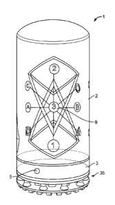
19 Turning now in detail to the drawings, the electronic
punching bags 1 shown in FIGS. 2-8A each have a display screen 3
21 which extends around more than half of the periphery of the
22 electronic punching bag 1. In FIG. 2, the display screen 3 is
CA 03032619 2019-01-31
WO 2017/024066
PCT/US2016/045412
1 shown with dotted lines as it extends around to the rear side.
2 The dotted lines show that for this embodiment the display
3 screen 3 extends around the complete periphery of the electronic
4 punching bag 1.
5
6 The display screen can extend, for example around 60% or
7 more of the periphery of the electronic punching bag 1, or
8 around 70% or more of the periphery of the electronic punching
9 bag 1, or around 80% or more of the periphery of the electronic
10 punching bag 1, or around 90% or more of the periphery of the
11 electronic punching bag 1, or around 95% or more of the
12 periphery of the electronic punching bag 1, or around the entire
13 periphery of the electronic punching bag 1.
14
Because the display screen 3 extends around more than half
16 of the periphery of the bag and can extend completely around the
17 periphery of the bag, the display screen 3 can display an image
18 or a visual signal 5 and give the appearance that the image or
19 visual signal 5 moves around the bag clockwise or counter-
clockwise. This moving image or moving visual signal 5 leads or
21 prompts the boxer/athlete being trained to follow the image or
CA 03032619 2019-01-31
WO 2017/024066
PCT/US2016/045412
11
1 signal 5 and move himself or herself clockwise or counter-
2 clockwise around the bag 1.
3
4 The electronic punching bag 1 will help athletes improve
their performance by making it possible to train their physical
6 and mental capabilities. With electronics and software
7 integrated into the bag, the electronic punching bag 1 enables
8 customized exercise which involves visual stimulus processing
9 and reaction tracking. The bag 1 makes it possible to measure
the reaction time of the boxer/athlete with respect to the
11 visual stimulations when the boxer/athlete is fatigued. The bag
12 1 allows for pre-programmed trainings and an ability to
13 integrate new trainings according to the boxer/athlete's needs.
14
The electronic punching bags 1 shown in FIGS. 2-8A each
16 have an elongate bag 2 formed of resilient material. The
17 elongate bag 2 in one embodiment is cylindrical. The elongate
18 bag 2 can withstand being punched by the boxer who is training
19 using the electronic punching bag 1. Centrally located in the
elongate bag 2 may be a piping core that is standard for heavy
21 punching bags. The resilient material may be that used in known
22 punching bags or in known heavy punching bags.
CA 03032619 2019-01-31
WO 2017/024066
PCT/US2016/045412
12
1
2 The display screen 3 can be an LED matrix display or an LCD
3 monitor that is a computer screen. In one embodiment the
4 display screen 3 can project a digital image or visual signal 5
in a manner that gives the appearance that the digital image or
6 visual signal 5 moves clockwise or counter-clockwise around the
7 display screen 3. Implied in the definition of display screen
8 is that the screen extends continuously or essentially
9 continuously around the periphery and not in merely unconnected
individual sections. For those embodiments in which the display
11 screen 3 is an LED matrix, the LED matrix is flexible. The
12 flexible LED matrix would include LED flashes. LED matrix
13 drivers drive the LED matrix or matrices.
14
The display screen may be assembled by being manufactured
16 in multiple separate curved sections. The curved sections would
17 be affixed to the bag or frame and aligned next to each other
18 such that the display screen appears to extend continuously
19 around the periphery. Despite these various sections, the
assembled display screen functions as a continuously extending
21 screen around the bag. For example, the display screen could be
22 formed from four curved sections, each of which extends over an
CA 03032619 2019-01-31
WO 2017/024066
PCT/US2016/045412
13
1 arc of 90 degrees, so that when all four curved sections are
2 fixed to the bag and aligned with each other, the display screen
3 extends around all 360 degrees of the bag in a ring shape. The
4 display screen could be formed from two such sections extending
around 180 degrees. The display screen could be formed from
6 three such sections each extending 120 degrees. For those
7 embodiments in which the display screen extends around more than
8 half of the periphery of the bag but not around the complete
9 periphery of the bag, the display screen could still be
manufactured in multiple separate curved sections. For example,
11 for a display screen that extends around two/thirds of the
12 periphery of the bag, the display screen could be formed from
13 two separate curved sections which each extends around one/third
14 of the periphery of the bag.
16 The visual signals 5, e.g. an array of colored lights or
17 graphic effects, can be displayed on the display screen 3 at
18 various positions around the periphery of the bag 1 so that via
19 the signals 5 the boxer can be prompted to move to various
positions clockwise or counter-clock-wise around the bag 1 to
21 punch at various positions on the bag 1 dispersed clockwise or
22 counter-clock-wise around the bag 1. The visual signal 5 can
CA 03032619 2019-01-31
WO 2017/024066
PCT/US2016/045412
14
1 randomly pause or switch speeds and directions at any time. The
2 boxer is in one training session embodiment expected to stay
3 within arm's reach of the visual signal 5 at all times. Once
4 the visual signal 5 stops, the display screen 3 can display or
flash patterns 7 that may be a number or a color to indicate to
6 the boxer what punch or punch combination should be thrown and
7 to what part of the elongate bag 2. Under a more advanced
8 training program, a pattern 7 could flash indicating a punch
9 should be thrown even while the visual signal 5 moves. This
moving pattern 7 causes the boxer to need to punch while he or
11 she moves.
12
13
In the embodiments of the electronic punching bag 1 shown
14 in FIG. 4A and in FIG. 7A, the microprocessor 4 is shown. In
these embodiments, the microprocessor 4 is disposed in an
16 interior of the electronic punching bag. The microprocessor 4
17 may also be disposed at a periphery of the electronic punching
18 bag 1. The embodiment shown in FIG. 7A includes the
19 microprocessor 4 being disposed in an upper region of the
elongate bag 2, but the microprocessor 4 will usually be
21 disposed in a display screen portion 35 of the bag 1 interior
22 from the display screen 3 and protected by the shock absorbing
CA 03032619 2019-01-31
WO 2017/024066
PCT/US2016/045412
1 section. FIG. 4A shows this usual positioning of the
2 microprocessor 4, with the microprocessor 4 being shown in
3 dotted lines due to it not being visible from the exterior of
4 the bag 1 and being positioned behind the display screen 3.
5
6 The microprocessor 4 is configured to send signals to the
7 display screen 3 to control the display screen 3 and to cause
8 the display screen 3 to display the visual signals 5 and
9 patterns 7 such as colors, identifications, symbols, or a
10 question such as an equation. The microprocessor 4 includes
11 memory storage and may also be connected with a separate memory
12 storage device for enhanced memory space. Predefined training
13 programs can be saved in the memory storage or in the separate
14 memory storage device. Training programs could be wirelessly
15 transmitted to the microprocessor from a smart phone and the
16 memory could save the newly-uploaded/downloaded training
17 program. The microprocessor is programmed with software to
18 cause the bag 1 to execute the training program. The
19 microprocessor 4 can be disposed on a printed circuit board.
21 FIGS. 3B and 3C show sensors 6 that are embedded in the
22 elongate bag 2 in order to sense punching performance of a boxer
CA 03032619 2019-01-31
WO 2017/024066
PCT/US2016/045412
16
1 using the electronic punching bag 1. A plurality of sensors 6
2 are distributed throughout the elongate bag 2. In one
3 embodiment, the sensors 6 can be embedded from one to two inches
4 into the interior from the exterior surface of the elongate bag
2. FIG. 3B shows a cross-section of an exterior portion of the
6 elongate bag 2 of the electronic punching bag 1 from FIG. 3A.
7 FIG. 3B shows that in this embodiment the sensors 6 are disposed
8 between an absorbing foam layer 12 and a supporting foam layer
9 34. An outer covering layer 32 contacts the absorbing foam
layer 12. The outer covering layer 32 can be made of vinyl or
11 canvas or leather or a similar material. The sensors 6 are
12 impact sensors so that each sensor can sense an overall force
13 absorbed by the sensor 6. The sensors 6 could also give a
14 binary indication of positive or negative as to whether a punch
has been landed with some error of margin. The sensors can also
16 recognize the accuracy of a punch to sense whether the punch was
17 a direct hit or only a partially direct hit.
18
19 The sensor technology can be similar to the sensor
technology implemented in a Daedo electronic body protector
21 worn by kickboxers.
22
CA 03032619 2019-01-31
WO 2017/024066
PCT/US2016/045412
17
1 FIGS. 2 and 7A-7D show target symbols 9 disposed on an
2 exterior of the elongate bag 2. Each target symbol 9 is aligned
3 with a respective sensor 6, as is shown in FIG 3B. The target
4 symbols 9 may be a character, another symbol, a shape such as a
square, a triangle, or a circle, and also may have a particular
6 color incorporated therein. The target symbols 9 may be divided
7 into groups or symbolic matrices distributed around the
8 periphery of the bag. For example, the electronic punching bag
9 may include three symbolic matrices of nine target symbols each
so that the embodiment has a total of twenty-seven target
11 symbols distributed around the bag. Each matrix of target
12 symbols may constitute a symbolic puzzle or a brain maze. In
13 another embodiment, the electronic punching bag may include
14 three matrices of six target symbols each so that the embodiment
has a total of eighteen target symbols distributed around the
16 bag. The target symbols 9 cans glow in the dark.
17
18 For the embodiment with a total of twenty-seven target
19 symbols 9, the electronic punching bag 1 would usually have a
total of twenty-seven sensors 6 embedded in the electronic
21 punching bag, with each sensor 6 being aligned with a particular
22 target symbol 9 so that the sensor 6 senses a punch to the bag 1
CA 03032619 2019-01-31
WO 2017/024066
PCT/US2016/045412
18
1 at that target symbol 9. Optimized placement of the sensors 6
2 in the bag 1 improves the durability and sensitivity of the
3 electronic punching bag 1.
4
The sensors 6 are connected with the microprocessor 4 to
6 send sensor signals to the microprocessor 4. Due to this
7 connection, the sensing of the sensors 6, and the processing
8 ability and memory of the microprocessor 4, a punching
9 performance of a user using the electronic punching bag can be
tracked via the microprocessor 4. The connection between the
11 sensors 6 and the microprocessor 4 can occur via wiring or via a
12 wireless connection. FIG. 3C shows a sensor 6 which senses
13 pressure and which has a physical wiring connection that runs
14 from it to the microprocessor and possibly to other sensors 6.
16 The signals from the microprocessor 4 to the display screen
17 3 cause the display screen 3 to display at least one visual
18 signal pattern 7 representing at least one target symbol 9 of
19 the elongate bag 2. Thus, when the boxer sees the pattern 7 he
or she then knows which target symbol 9 on the elongate bag to
21 punch. For example, the pattern 7 may be a yellow "3" or a red
22 "A" prompting the boxer to punch the yellow 3 or the red A that
CA 03032619 2019-01-31
WO 2017/024066
PCT/US2016/045412
19
1 is visible on the bag. The patterns 7 can be in the form of
2 variously colored lights, colored cursors, symbols, shapes,
3 and/or a fireball which match with certain color regions on the
4 punching region of the bag so that the display of a particular
pattern 7 on the monitor, i.e. the display of a red light, would
6 prompt the boxer to punch a red colored region in the elongate
7 bag 2 above the display screen 3.
8
9
The patterns 7 can be given in combinations to prompt the
boxer to throw a particular combination of punches at certain
11 regions and target symbols 9 of the punching bag. The pattern
12 cursor could move and then stop and flash a color code to prompt
13 the boxer to throw a particular punch combination. In one
14 instance, the pattern 7 is displayed on the display screen 3 as
a quick succession of a green pattern, then a yellow pattern,
16 and then a red pattern indicating to the boxer that he or she
17 should punch the green target symbol 9, then the yellow target
18 symbol 9, and then the red target symbol 9. In one embodiment,
19 the target symbols 9 do not light up and each target symbol
maintains a permanent color. In another embodiment, the target
21 symbols 9 themselves could light up. For example, FIG. 7A shows
22 the punch combination B-3-1 which prompts the boxer to
CA 03032619 2019-01-31
WO 2017/024066
PCT/US2016/045412
1 sequentially punch target symbols labeled as B, 3, and 1 on the
2 elongate bag 2.
3
4 The pattern 7 could also signal to the boxer to perform
5 other intermittent exercises, such as for example to perform
6 five jumping jacks.
7
8 The pattern 7 can also be an equation or a question, and
9 a correct answer to the question corresponds to at least one
10 target symbol 9. For example, as shown in FIG. 7C the pattern 7
11 can be the equation 7 minus 4 = ? When the boxer, sees the
12 equation he can calculate in his or her mind that the answer to
13 7 minus 4 is three. This equation is, therefore, a prompt to
14 the boxer/athlete that he or she should punch the target symbol
15 designated with a "3" on the elongate bag 2.
16
17 The display screen 3 could show two symbols moving towards
18 each other, one being a bland target symbol and one matching a
19 target symbol 9 on the bag. When the two symbols reach each
20 other on the screen and overlap, this is the signal for the
21 boxer to punch the target symbol 9 on the elongate bag 1 which
22 matches the display screen symbol.
CA 03032619 2019-01-31
WO 2017/024066
PCT/US2016/045412
21
1
2 The equation or question could also include IQ test
3 questions in which multiple groups of symbols are shown, and the
4 boxer must identify what is the same or different from the
various groups of symbols. The answer to this riddle matches at
6 least one target symbol 9 on the elongate bag and thus, the
7 boxer is prompted to punch that particular target symbol.
8
9 Thus, with this feature the electronic punching bag 1 can
help an athlete achieve enhanced training because his or her
11 thinking and reasoning abilities are tested even when he or she
12 might be weary from the workout. The pattern 7 can also give
13 information about what type of punch should be thrown, such as a
14 right or left body shot, a right or left upper cut, a right
straight jab or a left straight jab, a right or left hook, or a
16 combination of these punch types. A video camera disposed in
17 the device could record the boxer to determine and sense and
18 communicate to the microprocessor 4 whether the proper punch
19 type was punched by the boxer.
21 The electronic punching bag 1 and its screen 3 and its
22 light 17 help encourage the boxer/athlete to move, help
CA 03032619 2019-01-31
WO 2017/024066
PCT/US2016/045412
22
1 challenge his or her lateral agility, help develop his or her
2 hand-eye coordination, help build endurance, and help the boxer
3 to learn to stay focused.
4
The microprocessor 4 can have a built-in timer so that the
6 microprocessor 4 can track the reaction time of how long it
7 takes the boxer to land a punch at the correct target symbol
8 based on a particular pattern 7 being displayed at the display
9 screen 3. The timer can track with an accuracy in milliseconds.
Thus, with this embodiment of the microprocessor 4 it is
11 possible to track the performance of the boxer during fatigue
12 conditions. The boxer is generally given a time of from one to
13 three seconds from the displaying of the pattern 7 until he or
14 she is expected to land the punch at the target symbol 9 that
corresponds to the particular pattern 7 that was displayed. Via
16 the control unit 11 or via a smart phone communicating
17 wirelessly with the bag 1, the boxer could control the
18 difficulty level of the training session to adjust how much time
19 can elapse between the pattern 7 display and landing a punch in
order for the punch to be considered timely.
21
CA 03032619 2019-01-31
WO 2017/024066
PCT/US2016/045412
23
1 The electronic punching bag 1 will be formed with
2 synchronization between the display screen 3, the patterns 7
3 generated at the display screen 3, the sensors 6, and the built-
4 in timer of the microprocessor 4 so that the performance of the
boxer is accurately evaluated.
6
7 The microprocessor 4 is also configured to receive and
8 transmit a wireless signal and to receive instructions via the
9 wireless signal.
11 The microprocessor 4 can generate a performance report
12 about the success of the boxer with respect to (1) his or her
13 timely punching of the correct target symbols and/or (2) the
14 power of the punches thrown and/or (3) the accuracy of the
punches thrown and/or (4) the types of punches thrown. In the
16 report, one number could be a total punch count and another
17 number could be an impact punch count. The report can include a
18 review graph. Only punches delivered within a specified
19 reaction time would qualify as an impact punch. The reaction
time could be, for example, less than one second or less than
21 three seconds. The microprocessor 4 can wirelessly send this
22 performance report to another computer or to a handheld computer
CA 03032619 2019-01-31
WO 2017/024066
PCT/US2016/045412
24
1 device. For example, the electronic punching bag 1 may be
2 equipped with a transmitter 19 to allow a wireless communication
3 between the microprocessor 4 and a handheld smart phone so that
4 the microprocessor 4 sends the performance report to the smart
phone. The transmitter could in one embodiment receive and
6 transmit short-wavelength ultra-high frequency radio waves, e.g.
7 could be a Bluetooth transmitter 19.
8
9 Via the transmitter 19, the bag 1 could also communicate
with a heart-rate monitor that is worn by the boxer/athlete.
11
12 The microprocessor 4 could alternatively send this
13 performance report to be displayed at the screen of the control
14 unit 11 or on the display screen 3. The microprocessor 4 could
also communicate information about the report via the audio
16 speaker 24 to give encouragement or correction to the boxer
17 during the training/punching session.
18
19 Likewise, an exerciser can determine a particular program
or routine to use for a training session and can make a
21 selection on his or her smart phone of the program or routine to
22 be implemented by the electronic punching bag. Via the
CA 03032619 2019-01-31
WO 2017/024066
PCT/US2016/045412
1 Bluetooth wireless communication 19, e.g. shown in FIG. 7A, the
2 selection can be sent to the microprocessor 4 so that the
3 microprocessor 4 will control the electronic punching bag 1 and
4 the display screen 3 to implement the selected training program.
5 In other words, in this embodiment the wireless communication
6 feature supplements or obviates the need for the control unit
7 11.
8
9 The microprocessor 4 may also be programmed with multiple
10 training programs so that upon its arrival and initial setup in
11 a home or a gym, these training programs can be undertaken by a
12 boxer.
13
14 The electronic punching bag may also include a control unit
15 11 disposed on an exterior of the electronic punching bag 1 and
16 connected to the microprocessor 4. The control unit 11 may
17 include input devices 15 configured to receive programming from
18 a user. In the electronic punching bag embodiment shown in
19 FIGS. 4A-4B and 5A-5B, the input devices 15 are buttons or
20 switches. In the electronic punching bag embodiment shown in
21 FIGS. 6A and 6B, the control unit 11 is an LCD touch screen
22 which acts as a graphical user interface. Via the control unit
CA 03032619 2019-01-31
WO 2017/024066
PCT/US2016/045412
26
1 the user can select a training program or change training
2 regiment variables such as level of difficulty. The control
3 unit can give system and command control. For the embodiment
4 shown in FIGS. 6A and 6B with the LCD touch screen control unit
11, the control unit 11 may have a processor that is in addition
6 to the microprocessor 4 in order to handle the heightened
7 processing demands that result from the LCD touch screen control
8 unit 11. The screen control unit 11 can display feedback about
9 the status of the punching bag 1.
11
In some embodiments, the electronic punching bag also has
12 an audio speaker 24. The audio speaker has a connection to the
13 microprocessor 4 and is capable of giving audio commands and
14 prompts and feedback to the boxer. FIG. 7A shows an embodiment
with the audio speaker 24 disposed in an upper region of the bag
16 1. The audio speaker may alternatively be disposed in the
17 region near the control unit 11 or in some other portion of the
18 bag 1, for example as is shown in FIG. 4A where the audio
19 speaker 24 is disposed slightly above the display screen 3 and
below the elongate bag 2.
21
CA 03032619 2019-01-31
WO 2017/024066
PCT/US2016/045412
27
1 In some embodiments of the electronic punching bag 1, the
2 bag includes a light 17 configured to emit light downwards and
3 to project a line signal 23 on a surface below the electronic
4 punching bag 1 when the electronic punching bag 1 is suspended
in the air above the surface. The surface would usually be the
6 floor on which the boxer is standing. This line signal 23 gives
7 visual instructions to the boxer as to how he or she should
8 position his or her depth with respect to the punching bag 1.
9 For example, the line signal 23 can move to prompt the boxer to
move closer in next to the bag 1. Alternatively, the line
11 signal 23 can move to prompt the boxer to move further away from
12 the bag. The light 17 may be a laser light. FIGS. 4B, 5B, and
13 6B show an example of an electronic punching bag embodiment with
14 the light 17 that can be a laser light.
16 As shown in FIGS. 4B, 5B, or 6B, the line signal 23 can be
17 two concentric circles centered around a longitudinal axis of
18 the bag 1. In one embodiment, the circles growing in size can
19 prompt the boxer to distance himself or herself from the bag 1
and the circles decreasing in size can prompt the boxer to move
21 closer to the bag 1.
22
CA 03032619 2019-01-31
WO 2017/024066
PCT/US2016/045412
28
1 FIGS. 4A and 5A show an embodiment with a light 17 disposed
2 at a central portion of the bottom of the bag 1. FIG. 6A shows
3 an embodiment with a series of lights 17 distributed around a
4 periphery of the bottom of the bag 1.
6 The signals from the microprocessor 4 to the display screen
7 3 cause the display screen 3 to display a sequence of movement
8 of visual signals 5 and display of patterns 7 which together
9 constitute a boxing training regiment.
11 In one embodiment, the training regiment can include a
12 fight choreography of a past boxing match. For example, the
13 movement and punch combinations of Joe Frazier from his 1971
14 fight versus Muhammad Ali can be tracked and recorded and
programmed as a sequence of movements of the signal 4 and
16 display of patterns 7 such that the sequence represents a
17 choreography of Joe Frazier during his fight. A boxer who moves
18 and punches according to the sequence of the prompts from the
19 screen 3 of the bag 1 mimics the movement Joe Frazier did during
his fight and mimics the punches thrown by Joe Frazier during
21 his fight. In another fight choreograph program, the
22 microprocessor 4 is programmed with a choreograph of Floyd
CA 03032619 2019-01-31
WO 2017/024066
PCT/US2016/045412
29
1 Mayweather, Jr. according to his movement and punching in his
2 1998 fight againt Genaro Hernandez that lasted eight rounds.
3
4 The fight choreograph program would pause and give the
boxer a break between each round. The pause could last as long
6 as the actual fight pause of the historic boxing match or could
7 be a reduced time length. The user could adjust the pause time
8 between rounds using the control unit 11.
9
The fight choreography program or training regiment program
11 is saved in the microprocessor 4. A boxer using the bag 1 can
12 select the program using the control unit 11 or using his or her
13 computing device if the bag 1 has a wireless
14 transmitter/receiver. The bag 1 could be pre-programmed with
several such choreographs. A gym or an individual user could
16 also purchase additional fight choreographies from a central
17 computer database to upload these additional fight
18 choreographies to his or her electronic punching bag 1.
19
The professional fight choreography can be loaded as a
21 program and packaged with short video clips and a punch
22 glossary. Professional boxers could also market training
CA 03032619 2019-01-31
WO 2017/024066
PCT/US2016/045412
1 programs to be programmed into the electronic punching bag. The
2 consumer could download a training program from the professional
3 boxer that would prepare him or her for the choreographed fight,
4 and then after completion of the training program the boxer
5 could undergo the choreographed fight with the electronic
6 punching bag prompting him or her for each part of the
7 choreography.
8
9 The display screen is disposed in a display screen portion
10 35 of the electronic punching bag. FIG. 2 shows the display
11 screen portion 35 being disposed at a bottom of the punching bag
12 1, i.e. below the elongate bag 2 formed of resilient material.
13 The embodiments of FIGS. 4A to 7D also have the display screen
14 portion at a bottom of the punching bag 1. FIGS. 8A and 8B show
15 alternative embodiments in which the display screen portion 35
16 that includes the display screen 3 is disposed at a top region
17 of the bag 1, i.e. above the elongate bag 2 with resilient
18 material.
19
20 For some embodiments, at the bottom of the display screen
21 portion 35 is a shock absorbing section that protects the
22 display screen 3 and other electronic components if the bag 1
CA 03032619 2019-01-31
WO 2017/024066
PCT/US2016/045412
31
1 falls to the ground. The shock absorbing section typically
2 includes at least one shock absorbing device such as a spring
3 10a or 10b or hydraulics which provides flexibility and
4 cushioning in case the bag 1 were to fall to the ground.
6 FIG. 4 shows an embodiment in which the shock absorbing
7 section is a protective cage 44 that encases the display screen
8 3. The protective cage 44 is a solid frame cover, e.g. a metal,
9 plastic, or fiberglass frame cover, around the electric
components to protect all of the electric components in case the
11 bag 1 were to fall to the ground. The metal frame embodiment
12 may be formed from aluminum. In a further embodiment,
13 protective foam, e.g. sponge foam, could surround the protective
14 cage.
16 The protective cage 44 may be formed via three main
17 different structural parts - (1) a bag holding plate portion,
18 (2) a middle plate region, and (3) a strut region.
19
The bag support plate portion includes a bag support plate
21 41 underneath the elongate bag 2 and on which the elongate bag 2
22 rests. The bag support plate portion has a central piping 42
CA 03032619 2019-01-31
WO 2017/024066
PCT/US2016/045412
32
1 running upwards from the center of the bag support plate 41 to
2 provide a longitudinal inner support for the elongate bag 2.
3
4 The middle plate region includes an upper middle plate 43
that is connected to the bag support plate 41 via shock
6 absorbing devices such as springs 10a or hydraulics. The middle
7 plate region also includes a lower middle plate 45 that is
8 connected to the upper middle plate 43 via weight bearing posts
9 46. The cage 44 may include four, six, or eight or some other
number of these weight bearing posts 46.
11
12 The weight bearing posts 46 are disposed inside of the
13 outer periphery of the electronic punching bag 1, because the
14 display screen 3 sits in the space between the upper middle
plate 43 and the lower middle plate 45 at the outer periphery of
16 the bag 1. The upper middle plate 43 and the lower middle plate
17 45 can each include a lip to which the display screen 3 can be
18 connected.
19
The microprocessor 4 will also usually be disposed in the
21 middle plate region between the upper middle plate 43 and the
22 lower middle plate 45 within the interior of the middle plate
CA 03032619 2019-01-31
WO 2017/024066
PCT/US2016/045412
33
1 region. This placement of the microprocessor 4 allows the
2 microprocessor to be close to the display screen 3, the control
3 unit 11, and an audio speaker 24 in order to easily transmit
4 information and signals with these devices. Thus, when the bag
1 is fully assembled with the display screen 3 attached to the
6 upper middle plate 43 and the lower middle plate 45, the
7 microprocessor 4 is disposed inwards from the display screen 3
8 and is not visible from the exterior of the electronic punching
9 bag 1.
11 The strut region is disposed at the bottom of the
12 electronic punching bag 1 and is connected to the lower middle
13 plate 45 of the middle plate region via springs 10b or other
14 shock absorbing devices. The strut region includes a plurality
of struts 47, with each of the struts 47 extending from near a
16 central region of the electronic punching bag 1 to the outer
17 periphery of the electronic punching bag 1. The strut region
18 could have four struts, six struts, eight struts, or some other
19 number of struts.
21 The light 17 can be disposed at the center of the strut
22 region but is usually disposed higher upwards than the bottom of
CA 03032619 2019-01-31
WO 2017/024066
PCT/US2016/045412
34
1 the struts 47. Due to this positioning of the light 17, if the
2 bag 1 falls down the bag 1 will land on the struts 47 and will
3 not directly land on the light 17.
4
FIGS. 5A and 5B show an embodiment of the bag in which the
6 strut region is replaced by a soft pad 55. The soft pad 55 is a
7 soft shock resistant material applied at the bottom of the bag.
8 The soft pad 55 may be formed of an EVA foam. This embodiment
9 is a lighter embodiment due to the lightweight nature of the EVA
foam. The soft pad 55 may be rounded to have a hemispherical
11 shape. The soft pad 55 can be connected to the lower middle
12 plate of the middle plate region. In this embodiment, the light
13 17 can be disposed at a central bottom portion of the soft pad
14 55 so that the surface of the light 17 is disposed co-planar
with the bottom flat or curved surface of the soft pad 55. In
16 another embodiment, the soft pad 55 could be formed from
17 transparent material so that the light 17 is disposed further
18 upwards in the display screen portion and transmits light
19 downwards that runs through the soft pad 55 and still emerges to
form line signals 23 on the floor. Alternatively, for this
21 embodiment in which the light 17 is disposed upwards from the
22 soft pad bottom surface, the soft pad 55 could have holes
CA 03032619 2019-01-31
WO 2017/024066
PCT/US2016/045412
1 running therethrough which act as a light transmitting chamber
2 for the light 17 to send light downwards to form line signals 23
3 on the floor.
4
5 FIG. 6 shows an embodiment of the bag in which the strut
6 region is replaced by an air bag 63. The air bag 63 helps
7 absorb the shock if the bag 1 falls to the ground. The air bag
8 technology can be similar to air pockets at the bottom of some
9 athletic shoes. The air bag 63 can include a soft plastic frame
10 61 around one or more air pockets 62 with soft plastic weight
11 bearing posts 64 extending through the air pockets 62. The air
12 bag 63 can be connected to the lower middle plate of the middle
13 plate region. The one or more air pockets 62 are enclosed by an
14 outer transparent window to protect dust or dirt from entering
15 into the air pocket 62. The plastic of the air bag 63 can be
16 polyurethane or a similar plastic material to surround the
17 pockets that are filled with air or some inert gas.
18
19 For this air bag embodiment, the springs 10a or other shock
20 absorbing devices between the bag holding plate portion and the
21 middle plate region or between the middle plate region and the
22 air bag region are covered by respective sleeves 30 which
CA 03032619 2019-01-31
WO 2017/024066
PCT/US2016/045412
36
1 prevent dust or dirt from getting lodged in the spring area.
2 The sleeves nevertheless can slide upwards or downwards into
3 openings in the plates when the springs 10a, 10b are compressed
4 or extended due to a compression force.
6 FIGS. 2 and 7A-7E show an alternative embodiment in which
7 the shock absorbing section has an open configuration. This
8 configuration has air pockets running through it that are open
9 to the exterior. Numerous posts run through the air pockets
from a lower flat plate to an upper flat plate. The bottom of
11 this configuration includes numerous ribs running radially on
12 the bag bottom face on the bottom surface of the lower flat
13 plate and distributed spaced from each other around the bottom
14 face periphery. Soft or hard plastic or metal or other
materials can be used for the posts, plates, and ribs of this
16 configuration.
17
18 FIG. 8A shows an alternative embodiment of an electronic
19 punching bag 1' in which the display screen portion 35 and the
display screen 3 are disposed at the top of the bag 1' instead
21 of at the bottom of the bag 1'. A transform region 84 occurs
22 towards an upper part of the elongate bag 2. At the transform
CA 03032619 2019-01-31
WO 2017/024066
PCT/US2016/045412
37
1 region 84, the resilient material surface of the elongate bag 2
2 widens, e.g. in a conical manner, up to a maximum-sized
3 cylindrical region at the top of the bag 1'. This transform
4 region 84 can allow a boxer to practice different punches such
as an upper cut and a body shot.
6
7 FIG. 8B shows an alternative embodiment with a large
8 diameter heavy electronic punching bag 1". This embodiment also
9 includes the display screen portion 35 at the top of the bag 1".
The elongate bag 2 is below the display screen portion 35 and a
11 cushioning section 82 is disposed at the bottom of the bag.
12 With this embodiment, the elongate bag 2 can rotate while the
13 display screen portion 35 and the cushioning section 82 remain
14 stationary. Alternatively, the cushioning section 82 and the
elongate bag 2 could rotate together while the display screen
16 portion 35 remains stationary.
17
18 FIGS. 8A and 8B show a connection accommodation 26
19 configured to allow the electronic punching bag 1 to connect
with a connecting device 22 shown in FIG. 7E so that the bag 1
21 is suspended above the ground. The connection accommodation 26
22 could be one or more chain eyelets so that if the connecting
CA 03032619 2019-01-31
WO 2017/024066
PCT/US2016/045412
38
1 device 22 is a chain, the chain can engage with the chain
2 eyelet. The connecting device 22 could also be configured to
3 connect to a rope, a fabric strap, or a fabric rope for low
4 vibration. With the connection accommodation 26 and the
connecting device 22, the electronic punching bag 1 can be
6 adjusted to better match a boxer of a different height.
7 Specifically, the connection accommodation 26 could be attached
8 to a different higher or lower portion of the connecting device
9 22 to achieve this height adjustment.
11 FIG. 7D shows a connecting device 22 connected at the top
12 center of the electronic punching bag 1 and with a single
13 connection accommodation disposed at the top center.
14
FIGS. 8A and 8B show an embodiment of a connection
16 accommodation 26 that is a single eyelet at the top center of
17 the bag 1' or 1", with four fabric straps extending to the top
18 sides of the bag 1' or 1". The four fabric straps can be sewn
19 or attached into the bag 1' or 1" at the top sides of the bag 1.
Alternatively, the connection accommodation could be multiple
21 eyelets dispersed around the top of the bag 1.
22
CA 03032619 2019-01-31
WO 2017/024066
PCT/US2016/045412
39
1 The device could also include automatic adjustment features
2 and structure to allow adjustment of the height to better suit a
3 boxer with a different height.
4
In further embodiments, the electronic punching bag could
6 be supported from the ground instead of being suspended in the
7 air.
8
9 With some embodiments, the bag 1 includes an electrical
outlet so that the bag 1 can receive electrical power from a
11 power source such as an AC power input. The electrical outlet
12 can be disposed at a top region of the bag so that an electrical
13 power cord could be plugged into the bag from the top even
14 during a training session without interfering with the training
session. The external electrical power cord bringing power to
16 the bag 1 could run with or near the connecting device 22 that
17 suspends the bag 1 in the air above the floor. The electrical
18 outlet could also be disposed at a bottom region of the bag 1
19 near the display screen and the microprocessor.
21 The electrical outlet can, for example, be a 110V or 220V
22 AC input.
CA 03032619 2019-01-31
WO 2017/024066
PCT/US2016/045412
1
2 The bag 1 can include an AC/DC converter to convert AC
3 power to DC power for the main board of the microprocessor and
4 the driver circuits. The bag 1 may also include a DC/DC
5 converter to supply power to various internal components. This
6 second converter converts a DC input power into different levels
7 of DC power as needed by individual components.
8
9 The device may alternatively include a chargeable battery
10 system for powering the bag 1 so that the bag 1 does not need to
11 be plugged into an external power source during the training
12 session. The battery could be charged before and after and
13 between training sessions. The battery could in one embodiment
14 entirely replace the electrical outlet.
16 FIGS. 9 and 10 show two different electrical system
17 architecture embodiments for the electronic punching bag 1.
18
19 As shown in FIG. 7A, the longitudinal length 31 of the
display screen 3 can be at a 1:8 ratio with respect to the
21 longitudinal length 71 of the elongate bag 2. This ratio can be
CA 03032619 2019-01-31
WO 2017/024066
PCT/US2016/045412
41
1 within a range of from 1:3 to 1:10, for example can be 1:4, 1:5,
2 1:6, 1:7, or 1:9.
3
4 Although multiple embodiments of the present invention have
been shown and described, it is to be understood that many
6 changes and modifications may be made thereunto without
7 departing from the spirit and scope of the invention as defined
8 in the appended claims.
9