Note: Descriptions are shown in the official language in which they were submitted.
H8322694CADIV2
METHOD AND SYSTEM FOR INJECTING A PRESSURIZED
LIQUID STREAM WITH DISSOLVED GAS
FIELD
[0001] The
present disclosure relates to pressurizing a liquid, and
particularly to pressurizing an aqueous fluid with a gas to dissolve gas in
the
liquid for generating a stream of the liquid including small bubbles.
BACKGROUND
[0002] This
section provides background information related to the
present disclosure which is not necessarily prior art.
[0003] In
providing flow of a liquid, such as water, that is highly
supersaturated with a gas such as oxygen, within a host liquid, it has been
found
that the level of liquid flow rates that ensure laminar flow through small
bore
tubes is critical for providing bubble-free delivery of the liquid. For
example,
water that is supersaturated with oxygen at 1 ml 02/g water (at standard
temperature and pressure, upon release of the dissolved gas) can be delivered
through a silica tubing 100 microns or less in diameter within host liquids
without
bubble formation, for liquid flow rates of about 1 ml per minute. This flow
rate
allows for a flow that is laminar, and does not include any cavitation or
nucleation
sites for formation of bubbles. Such a system is disclosed in U.S. Pat. No.
5,569,180 to Spears. Such a system allows for the injection of the oxygen
supersaturated liquid without the generation of bubbles into a system that is
sensitive to the introduction of bubbles or other non-fully dissolved gases.
Such
1
CA 3032745 2019-02-05
H8322694CADIV2
sensitive systems include the human body in particular the vasculature system
within the human body.
[0004] Such a
system that introduces a substantially bubble-free
liquid into a host liquid, such as an intravascular space, does not permit
generation of bubbles during rapid dilution (for example, less than about 2-3
bars
equilibrium oxygen partial pressure upon mixing) in the host liquid. The tubes
for
such systems are designed to eliminate heterogeneous nucleation sites along
the inner surface of the tubes and at the proximal and distal ends of the
tubes.
SUMMARY
[0005] This
section provides a general summary of the disclosure, and
is not a comprehensive disclosure of its full scope or all of its features.
[0006]
According to various embodiments, a method of treating a
receiving volume of a first liquid with a transfer fluid is disclosed. A first
fluid can
be pressurized with a gas to saturate or create an emulsion of the first fluid
and
the gas to form the transfer fluid. The pressure can be at least 6 bar in a
containment vessel. The transfer fluid can be released from the containment
vessel and the released transfer fluid is passed through a tube or series of
tubes.
[0007] Various
Reynolds numbers in the effluent from the tube in a
range from about 2,220 to about 100,000 can be achieved. These Reynolds
numbers can be achieved by varying any aspect that may change the Reynolds
number. Reynolds number is generally defined as a dimensionless number
Re=pvl/ri, where p is density, v is velocity, I is length, and ri is viscosity
(CRC
2
CA 3032745 2019-02-05
H83226940ADIV2
Handbook of Chemistry and Physics, 86th Ed., Taylor & Francis, p. 2-47,
(2005)).
Each of the variables can be altered by materials selected, shape of the tube
and/or outlet, etc. The released transfer fluid can generate a dense
population of
micro-nanobubbles from the tube with the generated Reynolds number having an
average diameter that is about 50 microns or less in the receiving volume of
the
first liquid. The size of the micro-nanobubbles can be altered by selecting a
Reynolds number and the Reynolds number can be altered by varying one of the
elements of the Reynolds number calculation.
[0008] The present disclosure relates to pressurizing a liquid in the
presence of a gas to form an emulsion of liquid and dissolved gas and referred
to
herein as a transfer liquid or fluid. The liquid can be water, either pure or
with
contaminates. The transfer fluid can be delivered into a second fluid at
standard
temperature and pressure in a manner that forms a very high density of very
small bubbles of a predictable size but does not allow the gas to escape the
second liquid quickly.
[0009] A transfer fluid is provided that may be a liquid, such as
water,
that is supersaturated with oxygen or other gas for transfer of the gas to a
second volume of liquid and generation of bubbles within the second volume of
liquid. The bubbles can be formed due to turbulence of the mixing, phase
change of the gas in the transfer fluid, and incipient cavitation (growth of
gas
nuclei and growth of nanobubbles) in the transfer tube. Additionally, as
discussed
herein, the bubbles can be formed to include a diameter generally in a range
of
less than about 50 microns. Furthermore, the bubbles can have a diameter of
3
CA 3032745 2019-02-05
H8322694CADIV2
less than about 20 microns. At least a portion of the bubbles can have a
diameter less than 1 micron and generally in a diameter of many nanometers.
Such bubbles are referred to herein as micro-nanobubbles.
[0010] The bubbles can be used to oxygenate or transfer a selected
gas to a second body, such as a pool of water or slip stream of liquid, to
oxygenate the second body. Additionally, the transfer fluid, which has a
selected
saturation or partial pressure of gas, can be used to transfer the gas to the
second body. The small bubbles can be selected to be sufficiently small to
maintain the selected gas in the second body without quickly or immediately
rising to the surface and popping or expanding into the atmosphere.
Accordingly,
the selected gas can be maintained within the selected body for appropriate
purposes.
[0011] The body can include a contaminate material or a collection of
contaminated materials that are selected to be removed or degraded. An
appropriate enzyme, microbe or bio-nutrient can be introduced into the pool or
receiving volume of fluid that uses or enhances aerobic respiration in its
lifecycle.
Accordingly, a high concentration of oxygen can be used to assist in enhancing
the speed of the lifecycle and bioactivity of the microbe. The transfer fluid
saturated to a selected point with oxygen or air and injected into the
receiving
body to generate the formation of the bubbles allows access the oxygen source
by the microbes. The microbes can then perform the breakdown or degradation
of contaminate material within the receiving body for a selected purpose.
4
CA 3032745 2019-02-05
e,
H8322694CADIV2
[0012] The transfer fluid can also be substantially
pressurized with the
selected gas, including air or oxygen, and exit a nozzle at a selected
velocity and
flow rate. The density of the transfer fluid exiting the nozzle can include a
selected density that is substantially equivalent to a density of the transfer
fluid
leaving the supply vessel. The elevated velocity exiting the nozzles can serve
to
introduce the location of bubble formation to the surface of contaminated
materials. Accordingly, the pressurized transfer fluid can be used to emulsify
the
transfer fluid within the receiving fluid, such as water. The pressurized
transfer
fluid can be used to abrade a surface to remove a material from the surface.
Additionally, the small bubbles can be used to assist the abrasion or removal
process by exploding on the surface to assist in removal of a selected
material.
[0013] The transfer fluid can also be substantially
pressurized with the
selected gas, including air or oxygen, and exit a nozzle at a selected
velocity and
flow rate. The velocity and flow rate of the transfer fluid exiting the nozzle
can
include a selected pressure that causes the micro-nanobubbles to collapse and
form a radical (which could include superoxide anions, peroxides, hydroxyl
radicals, or hydroxyl ions) that is introduced into a vessel to be dissolved
in the
transfer fluid. Accordingly, the pressurized transfer fluid can be used
to
chemically oxidize contaminates of concern and/or dissolved metals.
[0014] The system and methods disclosed herein allow for
producing
dense clouds of micro-nanobubbles (bubbles that can have a population average
diameter of less than about 100 microns, less than about 50 microns, and about
nanometers to about 50 microns) in an aqueous liquid that simultaneously do
5
CA 3032745 2019-02-05
H8322694CADIV2
not require the use of additives, such as surface active agents or ions, to
achieve
the bubble size and quantity and allow the size of the majority of the bubbles
to
be easily adjusted from tens of nanometers to tens of microns. The bubbles can
also can be delivered into a host liquid with a transfer liquid having a high
gas:
carrier liquid (v:v) ratio (e.g., greater than about 0.1: 1) even for
sparingly soluble
gases such as oxygen and air. The system can be easily scaled up to industrial
levels, for example, 50 to many hundreds of gallons of transfer liquid/minute
for
treatment of millions of gallons of host liquids or treatment of environmental
surfaces encompassing millions of square meters. The bubbles can be delivered
in a transfer liquid at high velocity into water-immiscible liquids such as
oils for
producing fine oil-in-water and water-in-oil emulsions. The system can be used
for various purposes, including wastewater and environmental contaminate
treatment.
[0015] According to various embodiments, a very practical and
versatile way for delivering micro-nanobubbles at high gas densities and
velocities is disclosed. The potential applications of the invention are
numerous
and include treatment of wastewater containing a wide spectrum of contaminants
from any source, including domestic, municipal, industrial, and agricultural
origins. Treatment/aeration of any water, whether static or moving, contained
or
open, including ponds, lakes, bays, wetlands, marshes, estuaries, swamps, and
oceans; brooks, streams, and rivers; and groundwater, well water, aquifers,
and
water in other confinements such as ballast tanks and storage tanks. Treatment
of oil spills, including crude oil in or on any type of water or seawater in
any open
6
CA 3032745 2019-02-05
H8322694CADIV2
or contained location. Emulsification of water-immiscible liquids, such as
oils,
including crude oil and fuels, such as diesel fuel. Cleaning of any surface
coated
with water-immiscible liquids such as crude oil, including inanimate objects
such
as rocks, sand, coral, boats and other man-made objects; and animate objects
including plants and animals.
[0016] Another aspect of the disclosed tube and/or nozzle design is
that an adjustment of various parameters that affect a Reynolds number of flow
through the nozzle can be used to affect the size of the micro-nanobubbles,
because all or a significant number of sites of heterogeneous nucleation are
eliminated in the nozzle design. As discussed herein, various parameters can
affect or change the Reynolds number and these can affect the size of the
micro-
nanobubbles produced. The size of the micro-nanobubbles can be selected for
various applications.
[0017] Further areas of applicability will become apparent from the
description provided herein. The description and specific examples in this
summary are intended for purposes of illustration only and are not intended to
limit the scope of the present disclosure.
DRAWINGS
[0018] The drawings described herein are for illustrative purposes
only
of selected embodiments and not all possible implementations, and are not
intended to limit the scope of the present disclosure.
7
CA 3032745 2019-02-05
H8322694CADIV2
[0019] Fig. 1 is a schematic illustration of a fluid transfer system
and
body;
[0020] Fig. 2A is a schematic illustration of a tube according to
various
embodiments;
[0021] Fig. 2A1 is an end elevational view of a tube according to
various embodiments;
[0022] Fig. 2A2 is an end elevational view of a tube according to
various embodiments;
[0023] Fig. 2B is a schematic illustration of a nozzle according to
various embodiments;
[0024] Fig. 20 is an exploded schematic view of a nozzle with a
plurality of tubes;
[0025] Fig. 2D is a perspective view of a nozzle with a plurality of
tubes
within a housing;
[0026] Fig. 2E is an exemplary view of a transfer fluid being
injected
into a volume of water with the nozzle of Fig. 20;
[0027] Fig. 3 is an exemplarily view of a transfer fluid being
ejected at a
volume of water;
[0028] Fig. 4A is an illustrative view of a container holding a first
fluid
that is immiscible with a second fluid;
[0029] Fig. 4B is an illustrative view of a transfer fluid being
injected
into a container holding a first fluid that is immiscible with a second fluid;
8
CA 3032745 2019-02-05
H83226940ADIV2
[0030] Fig. 4C is an illustrative view of a maintained emulsion of
the
first fluid and the second fluid after an injection; and
[0031] Fig. 5 is a schematic view of a flow of transfer fluid
impinging
upon a surface.
[0032] Corresponding reference numerals indicate corresponding parts
throughout the several views of the drawings.
DETAILED DESCRIPTION
[0033] Example embodiments will now be described more fully with
reference to the accompanying drawings.
[0034] With reference to Fig. 1, a gas transfer system 8 can include
a
containment vessel 10 that is used to hold a transfer fluid 12 within an
internal
wall 14. The containment vessel 10 can also be referred to as a pressure
vessel
that is capped or lidded with a lid or containment top 16 to seal an internal
volume 18 of the containment vessel 10 defined by the internal wall 14 and the
containment top 16. The containment vessel 10, however, need not have a
flange lid, but can have any appropriate top which may be welded, adhered, or
otherwise enclose the internal volume 18. The transfer volume 12 can be held
within the containment vessel 10 until it is released through a tube or
passage,
the tube can be constructed as a dip tube 20 in the containment vessel. It
will be
understood, however, that the dip tube 20 withdrawal is not necessary and a
drain from the lower portion of the containment vessel 10 may be used.
9
CA 3032745 2019-02-05
H8322694CADIV2
[0035] The
transfer fluid 12 can pass through a nozzle tube or transfer
line 22 and through a nozzle 24, of selected dimensions. Between
the
containment vessel 10 and the nozzle 24, along the transfer line 22 can be
appropriate valves, such as a first valve 26, a second valve 28, and a third
valve
30. The valves 26, 28, and 30 can be appropriate valves including ball valves
to
cease flow of the transfer fluid 12 from the containment vessel 10.
Additionally,
appropriate regulators and pressure meters, such as a first pressure dial 32
and
a second pressure dial 34 can be used to monitor the pressure through the
transfer line 22 of the transfer fluid 12.
[0036] The
containment vessel 10 can be pressurized with a selected
gas from a selected gas source. The selected gas can be selected based on the
application into which the transfer fluid 12 will be transferred, and can
include
oxygen, helium, air, nitrogen, carbon dioxide, and other appropriate gases.
Also,
the gas can be provided in a liquid form before introduction into the
containment
vessel. Also a gas generation, such as an oxygen generation, system can be
provided to provide the gas. A first gas source can include a pressurized gas
container or cylinder 40 which can include a regulator system including a
pressure dial 42 and a first valve 44 that transfers a gas through a first gas
transfer line 46 through a second valve 48 and a second pressure dial 50 into
the
internal volume 18 of the containment vessel 10.
[0037]
Appropriate connections can be used to connect the gas
cylinder 40 to the containment vessel 10, such as those generally understood
in
the art. The gas cylinder can be a gas cylinder including those provided by
CA 3032745 2019-02-05
H83226940ADIV2
AIRGAS. A second gas source can include atmospheric air that is compressed
and pumped to the containment vessel 10 with a pump or compressor 60. A
selected compressor can be a hydraulic piston pump used to pressurize air to a
selected pressure.
[0038] Within the containment vessel 10, the gas, either from the gas
cylinder 40, the compressor 60, or other appropriate gas source can be used to
establish the operating pressurize of the transfer fluid 12 within the
containment
vessel 10. In pressurizing the transfer fluid 12 within the containment vessel
10,
to slightly above the established operating pressure, a portion of the gas
introduced into the containment vessel volume 18 can become dissolved within
the transfer fluid 12. The amount dissolved or concentration of the gas within
the
transfer fluid can depend on the solubility of the gas in the transfer fluid
12 and
operating pressure and the residence time in the pressure vessel. The transfer
fluid can be aqueous (e.g. plain water), non-aqueous, or mixtures thereof.
[0039] The transfer fluid 12, when including an appropriate amount of
dissolved gas, can be released through the dip tube 20 and the nozzle 24 into
a
receiving body or volume 66. The residence time in the vessel is generally
sufficient to fully saturate the gas in the transfer fluid 12 at the selected
pressure.
The receiving volume 66 can be any appropriate material, such as water, an
immiscible fluid (e.g. wastewater, process water, vegetable or food oils,
crude or
natural oils, or hydrophobic materials). The receiving volume 66 can be held
within a container 68. Alternatively, the receiving volume 66 can be a slip
stream
of liquid. Also, the receiving volume 66 can be an open or uncontained volume,
11
CA 3032745 2019-02-05
H83226940ADIV2
such as a river, stream, wetland, lake or ocean. Further, the receiving volume
66
can be a completely or partially container portion of a larger volume of
liquid,
such as a boom contained in a portion of a lake or ocean. For example, the
nozzle 24 can be used to direct the transfer fluid 12 into an open body of
water,
including a river, a lake, an ocean, or any other appropriate volume of
material.
Further, as discussed herein, the nozzle 24 can be used to direct the transfer
fluid 12 to a non-liquid surface for appropriate purposes, such as abrasion
for
cleaning.
[0040] As the transfer fluid 12 is removed from the containment
vessel
and ejected from the nozzle 24, make-up fluid can be introduced into the
containment vessel 10 to reduce or eliminate the possibility of emptying the
containment vessel 10. If the containment vessel 10 is emptied of liquid then
the
gas may escape in an uncontrolled manner. The fluid may be replenished with a
replenishing fluid from an appropriate transfer fluid source. It will be
understood
that once the containment vessel 10 is empty, the gas from the gas source,
including the gas cylinder 40 or the compressor 60 will escape at an
uncontrolled
rate and can no longer be efficiently transferred to the receiving volume 66
by the
transfer fluid 12.
[0041] According to various embodiments a recycle system 69 can
transfer a portion of the receiving volume 66 through a recycle line 70 back
into
the containment vessel 10. In the recycle system 69 a first pump 72 and a
second pump 74 can be used to move and pressurize a portion of the receiving
volume 66 to a pressure that exceeds the selected operating pressure in the
12
CA 3032745 2019-02-05
H83226940ADIV2
containment vessel 10. It will be understood that any appropriate number of
pumps can be used in the recycle system 69. The pumps can pressurize the
recycled portion to a pressure greater than that within the containment vessel
10.
Also, the recycle system can create a substantially closed system, but is not
necessary. For example, the recycle system 69 can be used in a slip stream
where the receiving volume 66 is flowing and continually being added to and
portions removed that have been treated with the transfer fluid (e.g. a river
or
wastewater slip stream).
[0042] Alternatively, or in addition to the recycle system 69, a
completely separate new fluid source 78 can be provided to replenish the
containment vessel 10 at an appropriate rate. A third pump 80 can be used to
pressurize the fluid from the new fluid source 78 before it enters the
containment
vessel 10. For example, the fluid from the new fluid source 78 can be
pressurized to a pressure higher than that in containment vessel 10. A valve
82
can be used to control the flow of the fluid from the new fluid source 78.
[0043] It will be understood that the refilling of the containment
vessel
with the replenishing fluid, either from the new fluid source 78 or the
recycled
fluid system 69 from the receiving volume 66 can equal a rate of removal of
the
gas transfer fluid 12 from the containment vessel 10. Thus, a selected amount
of
the transfer fluid 12 can be maintained in the containment vessel 10 for
dissolving the gas introduced into the containment vessel 10. This can allow
for
a continuous provision of the transfer fluid to the receiving volume 66.
13
CA 3032745 2019-02-05
H83226940ADIV2
[0044] It will
be understood, however, that according to various
embodiments the second pump 74 and the third pump 80 can be combined and
can be a variable speed pump. Thus, the replenishing fluid can come from
multiple sources through a single pump. Also, the variable speed pump can be
provided to ensure an appropriate volume of the transfer fluid 12 in the
containment vessel 10. That is
when the transfer fluid is lower in the
containment vessel 10 the variable speed pump can operate faster and then slow
when the volume is greater. It will be further understood, that any and all of
the
pumps 72, 74, and 80 can be variable speed pumps for the same purposes.
[0045] Regardless of the source of a replenishing liquid, the
replenishing liquid can enter the containment vessel 10 through a sprayer or
atomizer 84. The sprayed replenishing liquid can accelerate the dissolution of
gas used to pressurize the containment vessel as the replenishing fluid
resides in
the containment vessel prior to exiting through the dip tube 22. It will be
understood that if the recycling system 69 is used, therefore, that a portion
of the
material in the receiving volume 66 can be introduced into the containment
vessel 10. For example, contaminate materials, including surface active agents
(surfactants), microbes, microbial nutrients, oils, can be introduced into the
containment vessel 10 with the recycle system 69. These contaminants have
been shown to consume additional oxygen to partially chemically oxidize some
contaminants (notably ammonia, methane, and hydrogen sulfide) within the
pressure vessel without reducing the amount of oxygen delivered in the
transfer
fluid 12.
14
CA 3032745 2019-02-05
H8322694CADIV2
[0046] The volumes of the new fluid source 78, or the gas volumes
or
flow rates provided by the gas cylinder 40 or the compressor 60 and the volume
of the containment vessel 10 can be selected for various applications.
Additionally, the flow rate of the recycle pumps 72, 74 can be selected to
provide
the replenishing fluid to the containment vessel 10 at an appropriate rate. It
can
be selected to introduce the replenishing fluid from new fluid source 78 or
the
recycle system 69 at a selected pressure to the containment vessel 10 to
assist
with pressurizing the transfer fluid 12 within the containment vessels 10 and
overcoming the pressure from within the containment vessel 10.
[0047] According to various embodiments, the gas transfer system 8,
discussed above, can include a portion disclosed U.S. Pat. No. 5,569,180. For
example, the containment vessel 10 for the gas source, either from the
cylinder
40 or the compressor 60 can include vessels as discussed above. However, to
generate a transfer of gas via a very high density of micro-nanobubbles is
accomplished with a tube or nozzle of an appropriate dimension (along with
other
factors as discussed herein) for generation of the micro-nanobubbles in the
receiving volume 66.
[0048] With reference to Fig. 2A, a tube 100 can be included within
the
nozzle 24, illustrated in detail in Fig. 2B, either alone or as a bundle. The
tube
100 can be selected to include an internal diameter 102, a length 104, a
material
to coat or form at least an interior surface 106 of the tube 100. The internal
diameter 102 can be substantially uniform throughout the length of the tube
100.
A uniform internal diameter can assist in reducing nucleation points for
bubble
Date Recue/Date Received 2020-05-14
H8322694CADIV2
formation. The
material for the interior wall 106 can be selected to be
substantially hydrophilic. A substantially hydrophilic material, such as glass
including fused silica, can assist in micro-nanobubble formation as opposed to
a
hydrophobic material, including fluorocarbons (e.g. TEFLON ). Hydrophobic
materials produces substantially larger bubbles.
[0049] Fig. 2A1
illustrates an exemplary round or cylindrical internal
diameter 102 of the tube 100. The internal diameter 102 can be substantially
constant the length 104 of the tube 100. It will be understood that other
cross-
sections or internal configurations can also be provided. For example, an
elliptical or slit like opening, as illustrated in Fig. 2A2, can be provided
that
includes a small dimension 103 and a large dimension 103b. The small
dimension 103a and the large dimensions 103b can be substantially constant the
length 104 of the tube 100, but can provide a non-circular opening. It will be
understood that other appropriate cross-sections can include square,
rectangle,
oval, etc.
[0050] The micro-nanobubbles are selected to generally have a
diameter of less than about 100 microns, and particularly less than about 50
microns, and even further less than about 1 micron and measuring between 100
and 1000 nanometers. Further, a population of the micro-nanobubbles can be
formed to have an average diameter that is within the range disclosed above.
The micro-nanobubbles are formed in the receiving volume 66 after exiting the
tube 100. Generally, the transfer fluid 12 will leave the tube 100 as a liquid
lance
that is substantially similar in diameter to the internal diameter 102 of the
tube
16
CA 3032745 2019-02-05
H8322694CADIV2
100. Also, the transfer fluid 12 at the distal end of the tube 100 can be
rapidly
infused into the receiving volume 66 causing the combined fluid to have a
density
substantially similar to that of the non-gasenriched fluid that makes up the
transfer fluid 12.
[0051] The micro-nanobubbles can be used for various applications, as
discussed further herein, for introducing the gas into the receiving volume 66
(e.g. oxygenating the receiving volume 66). In providing the selected internal
diameter 102 and length 104 of the tube 100 the size of bubbles, generally in
a
micro-nanobubble range can be achieved. Additionally, the partial pressure of
the gas within the containment vessel 10 can be used to assist in generating
the
micro-nanobubbles.
[0052] Generally the internal diameter 102 can be greater than 100
microns and less than about 2.5 centimeters (about 1 inch). The length 104 of
the tube 100 can be selected to be an appropriate length which can be about
five
inches to about 15 inches, including about 5 inches, about 8 inches, and about
inches. In addition, the internal diameter 102 of the tube 100 can be provided
to be substantially uniform along the length 104 of the tube 100. Accordingly,
the
tube 100 need not taper and can define a substantially uniform inner cylinder
within the tube 100 thus having a substantially uniform cross-section
throughout
the length 104 of the tube 100. The tube 100, therefore, is not required to
include any choke points, waists, or tapers to allow for a generation of
turbulence
or nucleation points within or defined by the tube 100.
17
CA 3032745 2019-02-05
A
H8322694CADIV2
[0053] As is understood, generally in fluid dynamics, the
flow of a liquid
through a tube having particular internal dimensions and length can be defined
by a Reynolds number. The Reynolds number is also based upon various
factors including the velocity of the fluid, the density and velocity of the
fluid
flowing through the tube, and the dimensions of the tube. Accordingly, the
flow
rate and viscosity of a material, such as the transfer fluid 12, which flows
through
the tube 100 can affect the Reynolds number of the transfer fluid 12 through
the
tube 100. The Reynolds number can be selected to generate substantially non-
laminar flow and generate the micro-nanobubbles. As is understood, laminar
flow is generally deemed to be present when a calculated Reynolds number is
less than about 2300. Accordingly, a Reynolds number greater than about 2300
can be used to generate micro-nanobubbles.
[0054] The size and density of the micro-nanobubbles can be
augmented or selected based upon the Reynolds number generated with the
flow of the transfer fluid 12 through the tube 100. The factors can include
selecting the material of at least the internal wall 106 of the tube 100, the
internal
diameter 102 of the tube 100, and the length of the tube 104. Additionally,
the
partial pressure of the gas within the containment vessel 10 can be selected
to
also assist in achieving a selected Reynolds number to select the size of the
micro-nanobubbles generated when the transfer fluid 12 flows through the tube
100.
[0055] With reference to Fig. 2B, the nozzle 24 can include a
single
tube 100 connected to a handle/control system 110 at a selected joined area
18
CA 3032745 2019-02-05
H8322694CADIV2
112. The handle 110 can include a control mechanism 114 that includes an
external handle that operates an internal valve. It will be understood,
however,
that the nozzle 24 can be connected to a manifold system that allows the
nozzle
24 to be operated at a distance or a plurality of the nozzles 24
interconnected
together through use of a manifold system. For example, a plurality of the
nozzles 24 can be connected to a single supply, in series or in parallel, and
operated with a manifold to supply the supply line. The manifold can be
designed and operated in a manner that allows rapid decompression that causes
the supplying carrier fluid to pass the high pressure end of the tube
perpendicular
to the tube and thereby dislodge and remove particulates that may build up on
the inlet end of the tube 100 during operation. The connected nozzles 24 could
then be incorporated in other systems, such as floating boom placed in the
receiving volume 66.
[0056] With
continuing reference to Fig. 2B, a plurality of the tubes
100a, 100b, 100c can be interconnected to provide a plurality of the tubes
100a-c
in a generally parallel manner within a single one nozzle 24. It will be
understood
that any appropriate number of the tubes 100 can be interconnected with the
handle mechanism 110 to allow for the passage of the transfer fluid 12 through
the nozzle 24. The plurality of tubes 100a-100c, or any appropriate number
less
than or more than three, can be used to achieve an appropriate flow rate
through
the nozzle 24 that is not necessarily achieved through a single one of the
tubes
100. For example, if a flow rate of 66 milliliters per minute may be achieved
through a single one of the tubes 100, but a flow rate of approximately 500
19
CA 3032745 2019-02-05
H8322694CADIV2
milliliters per minute can be selected to flow through the single nozzle 24.
In
such a situation, a plurality, such as about 8, of the tubes 100 including
selected
dimensions can be interconnected with the handle mechanism 110 to assist in
achieving the selected flow rate. As discussed further herein, in the examples
described below, including the tube 100 of various selected dimensions can
achieve various selected flow rates through the nozzle 24.
[0057] The tube 100, or the plurality of tubes 100a-100c, can be
formed of selected materials to assist in achieving the appropriate Reynolds
numbers and the selected micro-nanobubble diameter through the nozzle 24.
For example, stainless steel, fused silica, fluorocarbons (e.g. Teflon ),
polymer
or plastic materials, ceramics, and the like can be selected to form the tube
100.
It will also be understood, however, that an appropriate physical
characteristics of
the wall 106 are selected or that the internal wall 106 can be coated or
formed of
a selected material and an external surface of the tube 100 can be formed of a
second material. Accordingly, a metal or stainless steel tube can be coated
with
a polymer coating to achieve an internal surface of a selected material.
[0058] Fig. 2C and 2D illustrates a nozzle 24a, according to various
embodiments of the nozzle 24, including a plurality of tubes 100a, according
to
various embodiments of the tube 100. In the nozzle 24a, any selected number of
tubes can be provided. Each of the tubes 100a is about 20 cm (about 8 inches)
long, such as about 19.8 cm (about 7.8 inches) to about 20.8 cm (about 8.2
inches) in length. The tubes have a substantially constant internal diameter
of
about 0.79 mm. Each tube is formed of stainless steel.
CA 3032745 2019-02-05
H83226940ADIV2
[0059] For example, 20 of the tubes 100a can be provided. If each
tube delivers about 0.25 gallons per minute then 20 of the tubes 100a can
provide about five gallons per minute. Thus, the number of tubes 100a can be
selected to achieve an nozzle 24a delivery volume rate.
[0060] The assembly of tubes 116 can be fit into a fitting 118. The
array of tubes can be in a cone configuration such that an outlet end 120a is
more disperse than an inlet end 120b. Within the fitting 118 the tubes 100a
can
be sealed together so that substantially no liquid can pass between the tubes
from the fitting 118, but substantially only through the tubes 100a. A cover
housing 122 can be positioned over the tube assembly 116 and mounted to the
fitting 118. An outer snap ring 123a and inner snap ring 123b can help hold
the
tubes within the outer housing 122. It will be understood that only one snap
ring
may be used or that a ring with drill or throughbores may be used
alternatively or
in addition to the two rings 123a, b.
[0061] As illustrated in Figs. 2D and 2E the outer housing 122 can be
held to the fitting 118 with one or more welds 124. The welds can be spaced
apart to define openings or passages 126. The passages 126 can allow liquid to
flow around each of the tubes 100a in the assembly 116. This can assist in
maintaining a selected bubble size from the tubes 100a. That is, each of the
tubes 100a in the assembly 116 can act independently to generate the selected
bubble size based on the calculated Reynolds number.
[0062] In Fig. 2E, the nozzle 24a is positioned within the receiving
volume 66. That is the nozzle 24a is submerged completely or a selected
21
CA 3032745 2019-02-05
H8322694CADIV2
amount within the receiving volume 66. A supply line 128 can supply the nozzle
24a. It will be understood that a plurality of the nozzles can be connected to
the
single supply line 128. Also, cleaning the inlet side of the nozzle can be
achieved by allowing the transfer fluid 12 to flow rapidly past the high
pressure
end of the nozzle 24a to dislodge and carry build-up from the inlet end of the
nozzle 24a down the supply line 128 generally in the direction of arrow 128a
instead of forcing it towards the nozzle 24a.
[0063] As
discussed above, the generation of micro-nanobubbles in the
receiving volume 66 by the flow of the transfer fluid 12 through the nozzle 24
can
be achieved by altering various characteristics. For
example, the internal
diameter 102 and the length 104 of the tube 100 can be used to achieve
appropriate Reynolds numbers. Characteristics of the tube 100, the transfer
fluid
12, the gas within the transfer fluid 12, and characteristics of the receiving
volume 66 can all be factors in determining the size of micro-nanobubbles. For
example, the internal surface being hydrophobic (when the transfer fluid 12 is
aqueous) can generate bubbles internally or provide nucleation points within
the
tube 100 for the growth of bubbles within the tube 100. Hydrophilic materials
generally allow for less bubble formation within the tube 100.
[0064] Also,
smooth surfaces on the internal surface 106 of the tube
100 can reduce nucleation points for bubble formation within the tube 100. A
smooth surface can be a surface that has values or peaks of less than about 50
nanometers, and further less than about 10 nanometers. Also, the end of the
tube 100 can be formed or polished to be substantially smooth having peaks or
22
CA 3032745 2019-02-05
H8322694CADIV2
values of less than 10-50 nanometers, Examples include fused silica or
polished
stainless steel tubes.
[0065] Additionally, the composition of the transfer fluid 10,
including
the type of fluid being aqueous fluid or non-aqueous fluids, can affect the
size of
the micro-nanobubbles. In addition, suspended particles, including the size
and
density, can affect the bubble size generation. The velocity of the transfer
fluid
12 passing through the tube 100, which can be referred to as a transit time or
a
tube transit time, can also affect the number and size of the micro-
nanobubbles.
Accordingly, a shorter tube, such as a shorter length 104, and a higher flow
rate
will decrease the tube transit time and minimize or eliminate nucleation of
bubbles within the tube 100, Additionally, the characteristics of the transfer
fluid
12 including temperature, density, and the like can also affect the bubble
size
and Reynolds number.
[0066] Characteristics of the receiving volume 66 can also affect the
micro-nanobubble size. The velocity, gas concentration, temperature, flow
rate,
turbulent nature of the receiving volume 66, and other physical characteristic
of
the receiving volume 66 can affect the size of micro-nanobubbles within the
receiving volume 66. Nevertheless, given the characteristics of the receiving
volume 66, the transfer fluid 12, and the partial pressure of the gas in the
transfer
fluid, the physical characteristics of the tube 100 can be selected to achieve
bubbles in the micro-nanobubbles size range in the receiving volume 66.
[0067] The micro-nanobubbles can refer to a mean or average
observed size of bubbles in a cloud of micro-nanobubbles 140 formed in the
23
CA 3032745 2019-02-05
H8322694CADIV2
receiving volume 66. As illustrated in Fig. 3, the receiving volume can be
held in
the tank 68. The cloud of micro-nanobubbles 140, as illustrated in Fig. 3, is
typically not visible to the naked eye and can be seen with various
interrogation
techniques, such as translumination. For example, the tank 68 can have
opposed clear walls 142 and 144 and a light source 146 can be directed at the
cloud of micro-nanobubbles 140 through the clear walls 142, 144. Scattering of
the light illustrated by hash marks 148 can assist in viewing the cloud of
micro-
nanobubbles 140. The light source 148 can include an incandescent light. Also,
a laser, such as an argon ion laser light, can be shown through the tank 68
and
the cloud of micro-nanobubbles 140. The light source 146 can be used to assist
in a human observer viewing the cloud of micro-nanobubbles 140 as a fine cloud
in the receiving volume 66. If the cloud of micro-nanobubbles 140 is
observable
only with argon ion laser translumination then it is concluded that the
average
bubble size in the cloud of micro-nanobubbles 140 is less than or equal to
about
1 micron or nanometer in size.
[0068]
Generally, as discussed above, the micro-nanobubbles can be
selected to be about less than 100 nanometers (nm) to about 200 microns,
including about 100 nm to about 100 microns, and further including less than
about 100 nm and less than about 50 microns. In a system where the transfer
fluid 12 is an aqueous fluid and the transfer fluid is saturated to about 0.1
ml of
oxygen (02) per gram of water to about 1.0 ml of oxygen (02) per gram of
water,
a Reynolds number of about 2,200 to about 100,000 can be used to generate the
micro-nanobubbles in the receiving volume 66. The range of Reynolds numbers
24
CA 3032745 2019-02-05
H8322694CA0IV2
can further includes about 5,000 to about 50,000. The pressure of the gas used
to achieve the levels of gas saturation in the containment vessel 10 can
include
about 4 bar to about 40 bar, including about 6 bar to about 30 bar, and
further
including greater than about 8 bar, such as about 20 bar.
[0069] EXAMPLES
[0070] In the following four micro-nanobubble examples and one
comparative example, exemplary dimensions of the tube 100 are discussed in
combination with the size of bubbles generated and calculated Reynolds
numbers related to the physical characteristics of the tube 100.
[0071] Examples Test Apparatuses
[0072] For Examples 1 and 2, a batch test apparatus was used, as
illustrated in the fluid delivery system 8 of Fig. 1, including the gas
cylinder 40,
the contaminant vessel 10, the nozzle 24 including a single tube of dimensions
discussed in the various examples, and the container 68 including the
receiving
volume 66.
[0073] In particular, the containment vessel 10 included a 600
milliliter
capacity 316 stainless steel Parr reactor vessel (from Parr Instruments, Inc.)
that
was filled with 500 milliliters of distilled water and pressurized with oxygen
to a
pressure of 300 psi (20 bars). The distilled water was then stirred at 1600
rpm
with a magnetic stirrer for at least two hours to saturate the water with the
oxygen
at the 300 psi. A dip tube, such as the dip tube 20, was connected in the Parr
reactor vessel and connected to an external delivery tube with an 0-ring
adapter
that allowed for a quick connection of a selected tube configuration. While
CA 3032745 2019-02-05
H8322694CADIV2
releasing the distilled water from the Parr reactor vessel, a cylinder filled
with the
oxygen (e.g. Airgas, Inc. standard Cylinder) was connected via a regulator to
the
Parr reactor vessel and the regulator maintained a 300 psi pressure to the
Parr
reactor vessel. The nozzle was used to inject the distilled water into a glass
aquarium filled with water drawn from a tap connected to a municipal source.
[0074] Interrogation and inspection for bubbles within the aquarium
included visual inspection by translumination (shining a light through the
aquarium tank and viewing the aquarium tank with the naked eye) with ordinary
light provided by an incandescent bulb and with a fiber optically delivered
beam
of chemical argon ion laser radiation. The argon ion laser radiation was from
an
approximately one watt source connected to a silica fiber optic cable (e.g.
400
micron core) with approximately 0.5 watts delivered to the distal end of the
fiber
optic core. All of the following examples were run at a temperature of about
20
degrees Celsius to about 21 degrees Celsius.
[0075] Concentration of oxygen was determined by filling a plastic
syringe having a rubber stopper plunger with about 20-30 milliliters of the
saturated water and closing one end of the syringe and tapping the syringe.
The
amount of movement of the plunger within the syringe was subtracted from the
volume of original saturated water drawn into the syringe. The difference is
calculated to be a conservative estimate of the volume of dissolved gas in the
saturated water because the liquid remains highly saturated with oxygen.
[0076] In Examples 3 and 4, a continuous flow test apparatus was
used due to the high flow rates. In particular, tap water from the same source
26
CA 3032745 2019-02-05
H8322694CADIV2
that filled the aquarium tank was boosted to a pressure of about 400 psi using
a
hydraulic piston pump and was delivered to a fine spray nozzle (e.g. a BETE
nozzle sold by BETE FOG NOZZLE, INC.) mounted within a 27 liter 316 stainless
steel pressure vessel. The pressure vessel was initially empty and pressurized
to about 300 psi with oxygen from a compressed oxygen cylinder. Water was
then sprayed into the 27 liter pressure vessel from the piston pump and
allowed
to mix with the pressurized oxygen within the 27 liter pressure vessel. The
vessel was then filled about half full (via measuring the weight of the
vessel) with
the pressurized tap water and then the saturated water was allowed to exit
through the tube. A test was used to determine, as discussed above, that the
concentration of oxygen in the water was about 0.5 milliliters of oxygen per
milliliter of water.
[0077] Examples 1 and 2 were also re-tested using the continuous flow
system with the 27 liter capacity pressure vessel and the source of
pressurized
tap water and substantially identical results were achieved.
[0078] Example 1 -
[0079] Tube: Formed of fused silica and included a constant internal
diameter of approximately 225 microns and a length of approximately 13
centimeters (about 5 inches). The tube was used to direct the distilled water
into
the aquarium tank filled with the municipal's tap water.
[0080] Reynolds number calculation: A Reynolds number of 6,075 was
determined based on a flow rate of 66 milliliters per minute and a flow
velocity of
27.7 meters per second.
27
CA 3032745 2019-02-05
H83226940ADIV2
[0081] Bubble interrogation: incandescent light revealed no visible
bubbles. Argon ion laser radiation revealed a prominent cloud of bubbles.
[0082] During the interrogation of the aquarium tank, no bubbles were
viewed with either incandescent lights or with the argon ion laser at the end
of
the tube within the aquarium tank. Interrogation with incandescent light did
not
allow for the observation of any bubbles. However, a faint cloud of bubbles
was
noted with argon ion laser illumination several centimeters from the end of
the
tube. Accordingly, without being bound by the theory, it was concluded that no
bubbles were generated within the tube and that all of the bubbles were
generated due to the turbulence of the mixing of the saturated water and the
tap
water. Additionally, due to the apparent non-presence of bubbles under the
interrogation with incandescent lights, but due the visibility of the bubbles
while in
interrogation with the argon ion laser radiation, the bubbles are concluded to
be
the micro-nanobubble size range, particularly in the sub-micron and nanometer
range.
[0083] Example 2 ¨
[0084] Tube: Formed of fused silica and included a constant internal
diameter of about 450 microns and about 13 centimeters in length (about 5
inches).
[0085] Reynolds number calculation: A Reynolds number of 5,670 was
determined based on a flow rate of 100 milliliters per minute and a flow
velocity
of 12.6 meters per second.
28
CA 3032745 2019-02-05
H83226940ADIV2
[0086] Bubble interrogation: With incandescent light a fine cloud of
bubbles appeared. With argon ion laser radiation a much denser fine cloud was
visible.
[0087] Substantially no large bubbles were observed, only a fine
cloud
of bubbles. Due to the visibility of both a fine cloud under incandescent
light and
laser light it is predicted that the bubbles were both nano-bubbles and micro-
bubbles. In particular, the micro-bubbles being several microns such as about
one to 20 microns. In particular, light microscopy was able to view bubbles in
the
20 micron and less diameter range. However, because the cloud appeared
denser with the argon ion laser it is predicted that the cloud included a
substantial concentration of bubbles having a diameter of less than one
micron.
[0088] Example 3 ¨
[0089] Tube: Formed of stainless steel and included a substantially
constant internal diameter of about 794 microns and a length of about 20
centimeters (about 8 inches).
[0090] Reynolds number calculation: A Reynolds number of 15,562
was determined based on a flow rate of 580 milliliters per minute and a flow
velocity of 19.6 meters per second.
[0091] Bubble interrogation: With incandescent light a faint cloud of
bubbles generally within a cone-shaped region extending from the end of the
tube was observed. The bubbles were substantially fine and an amount of large
bubbles was not generally observed. With the argon ion laser illumination, the
cloud appeared more dense, but still consisted of fine bubbles. The
observation
29
CA 3032745 2019-02-05
H83226940ADIV2
of fine bubbles under interrogation with both incandescent light and the argon
ion
laser light, with the density of the cloud of bubbles being viewed with the
argon
ion laser light interrogation confirmed that the bubbles were substantially
within
the 20 micron or less range, with a greater density being in the sub-micron
and
nanometer range.
[0092] Example 4 ¨
[0093] The continuous flow test system was used in Example 4 with a
300 psi driving pressure.
[0094] Tube: Formed of glass including a substantially constant
internal diameter of about 1 millimeter and a length of about 13 centimeters
(about 5 inches)
[0095] Reynolds number calculation: A Reynolds number of 43,300
was determined based on a flow rate of 2,040 milliliters per minute and a flow
velocity of 43.3 meters per second.
[0096] Bubble interrogation: With incandescent light a substantially
uniform and fine cloud of bubbles was observed. With argon ion laser light a
denser cloud was observed.
[0097] It is concluded that the bubbles formed with the glass tube
having an internal diameter of about 1,000 microns (1 millimeter) achieved a
cloud of bubbles that included micro-nanobubbles including a diameter of about
15 to about 20 microns and less, with a greater density having a diameter of
less
than about one micron.
[0098] Comparative Example-
CA 3032745 2019-02-05
H8322694CADIV2
[0099] Using
the batch test system described above with the 600
milliliter Parr reactor vessel a comparative example was tested.
[00100] Tube: Formed of fused silica including 100 microns, a length of
about 15 centimeters (6.0 inches).
[00101] Reynolds number calculation: A Reynolds number of 760 was
determined based on a flow rate of 3.6 milliliters per minute and a flow
velocity of
7.6 meters per second.
[00102] Bubble interrogation: With incandescent light and with argon
ion laser light substantially no bubbles of any density within the aquarium
tank
was observed.
[00103] It is concluded that the small diameter tube and low Reynolds
number achieved a substantially bubble-less flow of the oxygen-supersaturated
water into the aquarium tank. Even
upon exiting the tube into the tank,
substantially no gas was released or no bubble nucleation occurred from the
saturated water.
[00104] Accordingly, as illustrated in Examples 1 through 4, it can be
illustrated that the size of bubbles can be controlled by using various tube
sizes
and flow rates to achieve the formation of bubbles within the aquarium tank or
any appropriate receiving volume 66. Further, the diameter of the bubbles can
be maintained and controlled in a substantially sub-50 micron size, including
a
vast majority in a sub-micron and nanometer range. Accordingly, micro-
nanobubbles can be generated through a tube of selected physical dimensions to
allow for the injection of an appropriate or selected gas into the receiving
volume
31
CA 3032745 2019-02-05
H83226940ADIV2
66. The receiving volume 66 can be a liquid of an appropriate type, including
those discussed herein in various Applications, and can allow for transferring
a
gas from the saturated transfer fluid 12 to the receiving volume 66.
[00105] APPLICATIONS
[00106] There are different types of applications which may affect the
optimal geometry of a tube, as discussed herein. One application may be when
the nozzle 24 or tube 100 is placed directly in the receiving volume. Another
application can be when the nozzle 24 or the tube 100 is in air and ejecting
the
transfer fluid at a surface of the receiving volume 66.
[00107] When a distal (i.e. outlet) end of a tube is submerged under a
liquid a selected design for most such applications is a circular luminal
cross-
section at the distal end of the tube. The velocity of the transfer liquid
upon
contacting the host liquid to be treated is reduced less in comparison to
other
cross-sectional shapes (for a given luminal cross-sectional area) such as
elliptical, slit-like, square, or rectangular. Therefore, mixing of the
transfer liquid
with the host liquid is more effective, as is emulsification of water-
immiscible
liquids.
[00108] When the distal end of the tube 100 is in air and only the ejected
transfer fluid engages the receiving volume 66 then the selected design for
most
such applications, primarily ones related to cleaning of surfaces coated with
water immiscible liquids such as crude oil (in addition to enhancing aerobic
conditions during and after cleaning) can be a slit-like luminal cross-
sectional
shape at the distal end of the tube 100 while maintaining the selected
Reynolds
32
CA 3032745 2019-02-05
H8322694CADIV2
number. The shape of the transit liquid upon exiting the tube 100 is therefore
relatively wide in one dimension and can be fan-like, with the wide dimension
increasing with distance from the end of the tube 100. The transit liquid at
the
distal end of the tube 100 can flow between two roughly parallel plates, the
narrow space between which can be made to be adjustable during flow, or
through a fixed slit-like orifice, to produce a fan-like shape of the transit
liquid in
air. The advantage of such a shape is that relatively large surface areas of
objects to be treated can be treated quickly by moving the fan-like shape
across
the surface. The force of the tube 100 effluent per unit area of the treated
surface can be adjusted by adjusting the distance between the end of the tube
100 and the surface of the object. Of course, the force of the effluent can
also be
adjusted by other factors such as the hydraulic driving pressure at the input
of
the tube 100 and the width of the slit.
[00109] It will be understood that in the application where the transfer
fluid 24 is ejected through air that an array of the tubes 100 may also
provide an
optimal or selected coverage. For example, the circular area, as illustrated
in
Fig. 2C, can provide a large surface area of contact. Also, a linear area of
the
tubes 100 can provide a fan shaped coverage area. Thus, while each of the
tubes can maintain an internal circular configuration, the output may be any
selected shape.
[00110] Also, various applications can be optimized for different
materials of the tubes 100. For example, in highly corrosive environments,
like
sea water (salt water), substantially non-oxidizing materials may be selected
to
33
CA 3032745 2019-02-05
H8322694CADIV2
form or coat portions of the tubes. Coatings can be applied to stainless
steel, but
other metals can be used, such as titanium, tungsten, tungsten carbide, or
tantalum and/or corrosive resistant alloys like Inconel Metal Alloy (sold by
HUNTINGTON ALLOYS CORPORATION), HasteHoy (sold by HAYNES
INTERNATIONAL, INC.), And Monel (sold by HUNTINGTON ALLOYS
CORPORATION). Also,
non-metal materials such as glass, ceramic, or
polymers, can be used to eliminate or reduce corrosion.
[00111] Wastewater Treatment
[00112] As discussed above, the transferring fluid 12 can be injected
into the receiving volume 66 that is selected for various purposes. According
to
various examples, wastewater treatment can be enhanced by the addition of a
gas that has been dissolved in the transfer liquid 12 and the creation of the
micro-nanobubbles in a wastewater treatment facility. The wastewater treatment
can be wastewater or contaminated ambient water that is contained within a
substantially fixed tank or pond or provided in a wastewater slip stream. The
injection of the transfer fluid into a tank or pond can be similar to that
described
above with an appropriately scaled system to provide a selected rate of
injection
of the transfer fluid 12 into the wastewater pond. The transfer fluid can also
be
injected into a wastewater slip stream at an appropriate dilution, such as
about
20 parts wastewater to about 1 part injected transfer fluid. This can produce
a
wastewater slip stream that is about 40 parts per million injected transfer
fluid,
but still provide the oxygen, or other dissolved gas, at an appropriate level.
34
CA 3032745 2019-02-05
H83226940ADIV2
[00113] The introduction of the transfer fluid 12 into the wastewater can
assist in wastewater treatment and cleaning in various manners. For example,
upon collapse of the micro-nanobubbles extreme forces can be locally created
within the wastewater or receiving volume 66. The high temperature and
pressures can generate ions or radicals, such as hydroxyl ions (-OH). The
hydroxyl ions can accelerate or cause chemical oxidation of biological
materials
and even inorganic materials. Such
oxidation of materials in wastewater
generally makes the oxidized materials less harmful to other biological life,
such
as humans or animals, which later drink the water. In addition, the oxidized
materials can be more easily removed using various and generally known
removal techniques.
[00114] The micro-nanobubbles can also assist in floatation of small
particles that are present in wastewater. As discussed above, the bubbles can
form in substantially small sizes to allow for connection to or adhesion to
very
small particles within wastewater to allow for flotation. The micro-
nanobubbles
rise very slowly through the receiving volume 66, but nevertheless rise to
allow
for physical extraction of solids connected to a bubble. Further, a surfactant
can
either be present in the wastewater or be added to assist in the generation
and
density or number of micro-nanobubbles generated through the tube 100.
[00115] Selected naturally occurring and/or proprietary microbes,
enzymes and/or bio-nutrients, such as MicroSorb() microbial composition or
BioNutraTech chemical preparations sold by BioNutraTech, Inc. can be
introduced into a wastewater pond or volume to accelerate the biological
CA 3032745 2019-02-05
H83226940ADIV2
degradation of various contaminates in the wastewater. The rate
of
biodegradation is typically limited by the availability of oxygen. For
example,
microbes can be used to treat municipal, industrial and commercial wastewater
by digesting various contaminate chemical/biological species, including oil
such
in wastewater or contaminated water. Additionally, the contaminated water can
include water that is simply in or near a material to be removed, such as
water in
an ocean or lake that has been contaminated, at least partially, due to an oil
or
other chemical spill. Accordingly, contaminated water can include a selected
area or volume of water that is either contained or uncontained in a larger
body
of water and the microbe can be dispersed near the contaminate.
[00116] The oxygen or gas provided from the transfer fluid 12 to the
wastewater area can assist the microbe in the microbe's biological processes
by
accelerating the biological activity, increasing the population of contaminate
consuming microbes, and providing the physical mechanism (the emulsion) to
bring the contaminate, the microbe, the nutrient, and oxygen into very close
contact and thereby accelerating the entire process to assist in an increased
rate
of digestion and breakdown of the contaminate. For example, the micro-
nanobubbles can provide a large surface area for contacting all of the
elements
necessary for the degradation, including oxygen, microbe, nutrient, and
contaminate. In other words, the large number or small bubbles in the micro-
nanobubble size range allows for an appropriately sized package of oxygen for
use by the selected microbes. This oxygen package also provides surface area
for al of the relevant components, e.g. microbe and contaminate, to reside
during
36
CA 3032745 2019-02-05
H83226940ADIV2
degradation of the contaminate by the microbe. The bubble can also provide and
area to contact various compounds, such as metals, for oxidation.
[00117] For example, a microbe can be positioned near the contaminate
in a wastewater basin and the tube 100 can be used to introduce the transfer
fluid 12 into the wastewater as the receiving volume 66. The micro-nanobubbles
allow for a small volume that can be biologically active relative to the
microbe.
The microbe may phagocytize the micro-nanobubble to internalize the oxygen
present within the micro-nanobubble. Additionally, the micro-nanobubble may
connect to both the microbe and a portion of the contaminate to allow for a
proximity of the microbe, the contaminate, and a source of oxygen for aerobic
respiration of the microbe. It will be understood that additional nutrients,
such as
BioNutraTech can be added to assist in biological action of the microbe in
addition to the gas provided through the micro-nanobubbles.
[00118] Furthermore, other oxidizing agents can be added to assist in
oxidizing waste material and/or providing disinfection. For example, UV light
can
be caused to impinge on the wastewater to disinfect treated effluent prior to
discharge. A UV lamp can be provided to impinge on chemical wastewater to
provide UV radiation to chemically oxidize the constituent of concern. Various
studies have shown that chemical oxidants, such as hydrogen peroxide become
more cost effective when coupled with UV light. Additionally, a UV lamp can be
used to impinge UV radiation on a wastewater slip stream that is injected with
the
transfer fluid. The UV radiation can assist in oxidizing the waste material in
the
wastewater to assist in the breakdown and cleaning of the wastewater.
37
CA 3032745 2019-02-05
H83226940ADIV2
Impinging of the carrier fluid 12 into a wastewater pond or water volume is
illustrated in Fig. 1 within the tank 68 and also in Fig. 3 which illustrates
the
formation of a cloud of bubbles within a volume of water which can also
include
waste material to be removed either via biological degradation, oxidation, or
other appropriate methods. Other oxidizers, such as hydrogen peroxide, can be
added to the wastewater either alone or in addition to the UV radiation.
[00119] Emulsification
[00120] As illustrated in Fig. 4A, the receiving volume 66 can include a
first fluid 152 (e.g. water) may be immiscible with a second fluid 154 (e.g.
oil) or
may include only the second fluid 154 that is immiscible with the transfer
fluid 12.
The transfer fluid 12 can be injected, as illustrated in Fig. 4B, into the
substantially non-aqueous immiscible material, such as cooking oils (e.g.
canola
oil, vegetable oil, olive oil) or other types of immiscible material including
crude or
refined oil with the tube 100 that allows for generation of the micro-
nanobubbles
in the receiving volume 66. It will be understood that the tube 100 can be
submerged within the receiving volume 66, according to various embodiments.
[00121] As illustrated in Fig. 4C, after a period of time, the emulsification
of the aqueous transfer fluid 12 in the immiscible liquid is maintained. The
mixture can include, after a period of time, regions of substantially only the
first
fluid 150 and the second fluid 152. In addition, emulsification layers can
include
a first emulsification layer 154 that includes droplets of the first fluid
within the
second fluid and a second emulsification layer 156 that includes droplets of
the
second fluid in the first fluid.
38
CA 3032745 2019-02-05
H83226940ADIV2
[00122] Emulsification examples include water that has about 50
percent oxygen (vol 02/vol water) that is emulsified with Pennzoil 5W-30
weight
automobile motor oil that remains substantially emulsified, where it includes
at
least an emulsified portion, for at least 48 hours. Additionally, cooking oil
was
tested and maintained an emulsification region for at least about 72 hours
with
similarly oxygenated water. Accordingly, an emulsification of an aqueous
fluid,
such as water, with an immiscible liquid, such as oil, can be achieved and
maintained with the injection of the transfer fluid 12 without an addition of
a
surfactant.
[00123] In a particular example, the emulsification of the transfer fluid 12
and the vegetable oil was analyzed using a Coulter N4MD submicron particle
size analyzer. The analysis indicated that submicron, including droplets of
oil
within the water phase, persisted for at least about 3 days after injection of
the
transfer fluid 12 with generation of micro-nanobubbles into the vegetable oil.
Thus, an emulsification was generated and maintained for an extended period of
time without the use of any emulsification agent or surfactant.
[00124] Additionally, perflubron (perfluorooctyl bromide) formed an
emulsification upon the injection of the transfer fluid 12 (with the formation
of
micro-nanobubbles) that persisted for at least about 2 hours. By merely
shaking
a 1: 1 volume of the perflubron and water an emulsification lasted for less
than
one minute. Additionally, inspection of the aqueous phase for particle size
analysis with the Coulter N4MD submicron particle size analyzer indicated
submicron size particles of the perflubron in the aqueous phase after the
39
CA 3032745 2019-02-05
H8322694CADIV2
emulsification with the injection of the transfer fluid 12 and the formation
of the
micro-nanobubbles, without any surface active agents (surfactants).
[00125] The emulsification can also assist in providing for a dispersion
of the transfer fluid and the dissolved gas into the immiscible liquid. As
discussed above, this can assist in wastewater treatment and treatment of
selected materials by allowing for the formation of free radicals within the
immiscible liquids and delivery of oxygen or other gases into the immiscible
liquid
that can assist in bioactivity of microbes and other compounds. For example,
the
transfer fluid 12 can be injected into a waste material or contaminate (e.g.
crude
oil) along with the addition of microbes and an emulsion can be formed. The
emulsion can allow positioning of the micro-nanobubbles, including the
selected
gas (e.g. oxygen), to assist in the digestion of the waste material by the
microbes.
[00126] Surface Cleaning
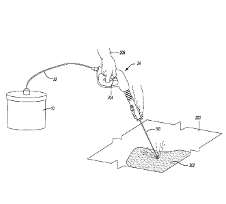
[00127] With reference to Fig. 5 a stream from the nozzle 24 could be
directed at a surface 200 that has been contaminated with a contaminate
material 202. The surface 200 can include inanimate or non-living surfaces
including a sea wall, a boat hull, a land mass, plant life, etc. Additionally,
the
surface can include animate or living surfaces such as those of animal
wildlife
(e.g. birds, reptiles, and mammals) and all varieties of vegetation. As
discussed
above, the generation of the micro-nanobubbles with the nozzle 24 can be done
with a plurality of flow rates and velocities. Thus, the force of impingement
on
CA 3032745 2019-02-05
H8322694CADIV2
the surface 200 can be tailored for the surface 200, such as a soft and
fragile
surface or a hard and sturdy surface.
[00128] In a test, eight light-colored granite rocks, 5-10 cm in diameter,
were covered with used Valvoline high grade synthetic motor oil. The used
motor oil could not be washed off the surface of the rocks with a conventional
water jet. However,
directing the transfer fluid 12 consisting of water
supersaturated with oxygen at 0.5 ml 02/m1 water, via an 8 in. long, 0.875 mm
constant internal diameter stainless steel tube (liquid flow = 600 ml/min.) in
air
against the rocks was successful in removing substantially all of the visible
indications of the used motor oil on the rock without the use or any other
additives, such as a detergent. The used motor oil that was removed was
observed to form an emulsion in the water, facilitating subsequent removal of
the
used motor oil from the surface of a plastic wash basin.
[00129] The contamination material could be oil (e.g. crude or refined
oil), fuel, adhesives, etc. The nozzle 24 could be attached to a manually
operated mechanism, such as including a trigger 204 that could be operated by
a
user 206. Alternatively, a remote manifold could be used to allow flow of the
transfer fluid through the nozzle 24 to direct the transfer fluid 12 towards
the
surface 200.
[00130] Impingement of the transfer fluid 12 on the contaminate material
and the surface 200 could immediately help remove the contaminate material
202 from the surface 200. Transformation of the contaminate material 202 into
a
fine emulsion, as discussed above, along with expansion of gas filled micro-
41
CA 3032745 2019-02-05
H8322694CADIV2
nanobubbles within the emulsion helps to lift the contaminate material 202 off
the
surface 200.
[00131] When directing the stream of the transfer fluid 12 through air the
sudden impact of the stream of the transfer fluid 12 against the surface 200
results in a very rapid expansion of micro-nanobubbles. The abrasive action of
the transfer fluid 12, the explosive release of micro-nanobubbles, and the
creation of a fine emulsion all help to clean the contaminate material 202
from
the surface 200. The emulsification can include micro-nanobubbles emulsified
in
the contaminate material 202 after impingement with the transfer fluid 12.
[00132] No surfactant is required to emulsify the contaminate material
202. Some surfactants can be harmful to both the object to be treated and the
surrounding environment. Thus, the emulsification and removal of the
contaminate material 202 without the use of any surfactants (e.g. soaps and
detergents) can assist in minimizing environmental impact in addition to the
contaminate material 202.
[00133] The foregoing description of the embodiments has been
provided for purposes of illustration and description. It is not intended to
be
exhaustive or to limit the invention. Individual elements or features of a
particular
embodiment are generally not limited to that particular embodiment, but, where
applicable, are interchangeable and can be used in a selected embodiment, even
if not specifically shown or described. The same may also be varied in many
ways. Such variations are not to be regarded as a departure from the
invention,
42
CA 3032745 2019-02-05
H83226940ADIV2
and all such modifications are intended to be included within the scope of the
invention.
43
CA 3032745 2019-02-05