Note: Descriptions are shown in the official language in which they were submitted.
ICE MELTING DEVICE FOR BLADE, BLADE AND WIND TURBINE
FIELD
[0001] The present application relates to the technical field of wind power
generation, and in
particular to an ice melting device for a blade, a blade having the ice
melting device and a wind
turbine.
BACKGROUND
[0002] The operating environment of a wind turbine directly affects the power
generation
efficiency of the wind turbine. In the case that the wind turbine is operated
under extreme
weather conditions such as frost, cold wave and freezing rain, phenomena of
ice (frost) coating
and snow hanging on a blade may occur. Due to the phenomena of ice (frost)
coating, snow
hanging and the like of the blade, a cross-sectional shape of the blade of the
wind turbine may be
changed, which reduces the efficiency of wind energy absorption of the blade;
a mechanical
operation damage of the wind turbine may be caused, the load of the wind
turbine may be
increased, and the center of gravity may shift; the falling of ice blocks
causes safety hazard to
field personnel and field equipment; and the accuracy of wind measurement may
also be affected,
which brings proprietors serious economic loss of power generation. For
example, the cumulative
number of ice-covered days in a wind farm in Gansu Province from October 2016
to April 2017
was more than 60 days, and the cumulative power generation loss is at least
6770.056 thousand
kilowatt hours.
[0003] In order to solve the phenomena of ice (frost) coating, snow hanging,
etc., the blade of
the wind turbine is generally deiced. Currently, the deicing methods include
passive anti-icing by
a solution, mechanical deicing, air thermal anti-icing, microwave deicing,
passive anti-icing by a
endothermic coating, deicing by electromagnetic shock vibration, passive anti-
icing by a
waterproof coating, trembling deicing, electro-thermal active deicing, etc.
The electro-thermal
active deicing method not only has the advantages of high power, small
influence on the
aerodynamic shape and good maintainability, but also is simple and direct, has
a high energy
utilization rate and low economic cost, therefore, it is a relatively ideal
deicing method and is
.. currently the most widely used and best-performing method.
-I-
CA 3032850 2019-02-04
[0004] An ice melting device for a blade which can perform active deicing by
using electric
energy is provided according to the present application.
SUMMARY
[0005] An ice melting device for a blade which has a novel structure and has
excellent heating
performance is provided according to the present application, to meet
practical needs.
[0006] According to an aspect of the present application, an ice melting
device for a blade is
provided. The ice melting device for the blade may include: a heating portion;
a first electrode
and a second electrode, wherein the first electrode and the second electrode
are arranged at two
ends of the first heating portion in a length direction, respectively; and a
connecting conductor,
wherein the connecting conductor extends in the length direction, a first end
of the connecting
conductor is connected to the second electrode, and a second end of the
connecting conductor and
the first electrode are located at a same side. With the connecting conductor,
power leads
connecting to the first electrode and the second electrode are allowed be
located at a same side,
thereby, in a case that an old blade is modified, an increase of a layer
thickness caused by the
power leads may be greatly reduced. In addition, the cumbersome wiring work
may be reduced
and the power leads may be saved.
[0007] Preferably, the first heating portion includes a glass fiber cloth and
carbon fiber strands,
the carbon fiber strands are sewn on the glass fiber cloth or the carbon fiber
strands are
interwoven with glass fibers of the glass fiber cloth, to be integrated with
the glass fiber cloth,
and the carbon fiber strands are conductively connected to the first electrode
and the second
electrode.
[0008] Preferably, the carbon fiber strands include longitudinal carbon fiber
strands and
latitudinal carbon fiber strands arranged on the glass fiber cloth in a
longitudinal direction and a
latitudinal direction respectively, and the longitudinal carbon fiber strands
and the latitudinal
carbon fiber strands are conductively connected to each other. With the mutual
conduction
between the longitudinal carbon fiber strands and the latitudinal carbon fiber
strands, the heating
effect of the melting device for the blade can be prevented from being
affected by the breaking of
a carbon fiber strand at a certain position.
-2-
CA 3032850 2019-02-04
[0009] Preferably, the longitudinal carbon fiber strands and the latitudinal
carbon fiber strands
are arranged crosswise, to form a grid structure with the longitudinal carbon
fiber strands and the
latitudinal carbon fiber strands cross each other at each node.
[0010] Preferably, the connecting conductor is a current-conducting sheet, the
connecting
conductor is sewn on the glass fiber cloth or arranged to run through the
glass fiber cloth, and the
connecting conductor is insulated from the first electrode and the carbon
fiber strands. By
insulating the connecting conductor from the first electrode and the carbon
fiber strands, an
electrical circuit is formed to avoid a short circuit.
[0011] Preferably, the heating device may further include: a second heating
portion, wherein
the heating portion and the first heating portion may be arranged side by side
in a width direction
of the first heating portion; a third electrode and a fourth electrode,
wherein the third electrode
and the fourth electrode may be arranged at two ends of the second heating
portion in a length
direction, respectively; the connecting conductor is located between the first
heating portion and
the second heating portion, and a first end of the connecting conductor may be
connected to the
second electrode and the fourth electrode respectively, and a second end of
the connecting
conductor may be located at a same side as the first electrode and the third
electrode. Since the
heating device includes the first heating portion and the second heating
portion, a blade may be
laid integrally by laying the first heating portion and the second heating
portion on a pressure
surface and a suction surface of the blade respectively, so as to save the
time and cost for
.. operation and maintenance.
[0012] Preferably, the first heating portion and the second heating portion
may be connected
through a glass fiber cloth, the connecting conductor may be a current-
conducting sheet and may
be sewn on the glass fiber cloth connecting the first heating portion and the
second heating
portion or may be arranged to run through the glass fiber cloth, the
connecting conductor is
insulated from the first electrode, the third electrode and the carbon fiber
strands. In a case that
the first heating portion and the second heating portion are arranged on the
pressure surface and
the suction surface of the blade respectively, the connecting conductor may be
located at a joint
between the pressure surface and the suction surface.
[0013] Preferably, a predetermined space is formed between the first heating
portion and the
-3-
CA 3032850 2019-02-04
second heating portion, the connecting conductor may be a wire and may be
accommodated in
the predetermined space. In a case that the first heating portion and the
second heating portion are
arranged on the pressure surface and the suction surface of the blade
respectively, the connecting
conductor may be located at the joint between the pressure surface and the
suction surface.
[0014] According to another aspect of the present application, a blade is
provided. The blade
includes the ice melting device described above, and the ice melting device is
built in the blade.
[0015] According to another aspect of the present application, a wind turbine
is provided. The
wind turbine includes the blade described above.
[0016] According to the ice melting device for the blade of the present
application, with the
connecting conductor, power leads connecting to the first electrode and the
second electrode are
allowed be located at a same side, thereby, in a case that an old blade is
modified, an increase of a
layer thickness caused by the power leads may be greatly reduced. In addition,
the cumbersome
wiring work may be reduced and the power leads may be saved.
[0017] In addition, according to the ice melting device for the bladeof the
embodiment of the
present application, the carbon fiber strands of the first heating portion is
fixed by the first
electrode and the second electrode and by an overlock treatment, which
prevents the carbon fiber
strands from loosing, so that the carbon fiber strands have a good performance
in maintaining a
stationary shape.
[0018] Besides, according to the ice melting device for the blade of the
embodiment of the
present application, by using the glass fibers as an insulating material,
carbon fibers in a carbon
fiber strand can be prevented from being mixed with the adjacent carbon fiber
strands, thereby
preventing a short circuit.
[0019] Moreover, according to the ice melting device for the blade of the
embodiment of the
present application, since the longitudinal carbon fiber strands and the
latitudinal carbon fiber
strands are conductively connected to each other, the heating effect of the
melting device for the
blade can be prevented from being affected by the breaking of a carbon fiber
strand at a certain
position.
[0020] Further, the ice melting device for the blade according to the
embodiment of the present
application may be designed to have different heating power according to the
requirements of the
-4-
CA 3032850 2019-02-04
blade, and may be integrally formed with a new blade or built in an old blade.
[0021] Furthermore, the ice melting device for the blade according to the
embodiment of the
present application has a simple manufacturing process and does not required
to be assembled in
use.
BRIEF DESCRIPTION OF DRAWINGS
[0022] The above and other objects and features of the present application
will be clearer from
the following description of embodiments in conjunction with the drawings.
[0023] Figure 1 is a schematic view showing an ice melting device for a blade
according to a
first embodiment of the present application.
[0024] Figure 2 is a schematic view showing an ice melting device for a blade
according to a
second embodiment of the present application.
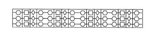
[0025] Figures 3 to 8 are schematic views showing that carbon fiber strands
and a glass fiber
cloth of a first heating portion are in combination.
[0026] Figure 9 is a schematic view showing an ice melting device for a blade
according to a
third embodiment of the present application.
[0027] Figure 10 is a schematic view showing an ice melting device for a blade
according to a
fourth embodiment of the present application.
[0028] Reference numerals in the figures:
10 first heating portion, 20 first electrode,
second electrode, 40 connecting conductor,
50 second heating portion, 60 third electrode,
70 fourth electrode.
25 DETAILED DESCRIPTION
[0029] The embodiments according to the present application will be described
in detail with
reference to the drawings, the embodiments are shown in the drawings, and the
same numeral
always represents the same component.
- 5 -
CA 3032850 2019-02-04
[0030] Figure 1 and Figure 2 show an ice melting device for a blade according
to an first
embodiment and a second embodiment of the present application, respectively.
Hereinafter, a
specific structure of the ice melting device for the blade will be described
with reference to
Figures 1 and 2.
[0031] As shown in Figures 1 and 2, an ice melting device for a blade may
include a first
heating portion 10, a first electrode 20 and a second electrode 30, and a
connecting conductor 40.
Specifically, the first electrode 20 and the second electrode 20 may be
arranged at two ends of the
first heating portion 10 in a length direction, respectively, to be
electrically connected to the first
heating portion 10. The connecting conductor 40 may extend in the length
direction of the first
heating portion 10,a first end of the connecting conductor 40 may be connected
to the second
electrode 20, and a second end of the connecting conductor 40 and the first
electrode 20 may be
located at a same side.
[0032] The connecting conductor 40 and the first electrode 20 may be connected
to a positive
power lead and a negative power lead at the same side, respectively, to allow
the first heating
portion 10, the first electrode 20 and the second electrode 30, and the
connecting conductor 40 to
form an electrical circuit, so that the first heating portion 10 is energized
to heat. Since the power
leads connecting the first electrode 20 and the second electrode 30 are
arranged at the same side,
compared with the method of connecting the first electrode 20 and the second
electrode 30 to the
power leads at the two ends of the first heating portion 10 respectively, an
increase of a layer
thickness caused by the power leads may be greatly reduced in a case that an
old blade is
modified. In addition, the cumbersome wiring work may be reduced and the power
leads may be
saved.
[0033] The ice melting device for the blade in Figure 1 is different from the
ice melting device
for the blade in Figure 2 in terms of a position of the connecting conductor
40 and a position of
connecting the connecting conductor 40 and the second electrode 30.
Specifically, in Figure 1, the
connecting conductor 40 is located at a first side of the first electrode 20,
and a second end of the
connecting conductor 40 is connected to a first end of the second electrode
30. However, in
Figure 2, the connecting conductor 40 is located at a second side of the first
electrode 20 opposite
to the first side, and the second end of the connecting conductor 40 is
connected to a second end
of the second electrode 30 opposite to the first end. It should be understood
that, the above
-6-
CA 3032850 2019-02-04
description is bases on the states of the ice melting device for the blade
shown in Figures 1 and 2,
regardless of the state of the ice melting device for the blade in actual use.
[0034] The first heating portion 10, the first electrode 20 and the second
electrode 30, and the
connecting conductor 40 will be described in detail hereinafter.
[0035] The first heating portion 10 may include a glass fiber cloth and carbon
fiber strands.
According to the design of the first heating portion 10, the carbon fiber
strands are sewn on the
glass fiber cloth, or the carbon fiber strands are interwoven with glass
fibers of the glass fiber
cloth, to be integrated with the glass fiber cloth. The carbon fiber strands
may be conductively
connected to the first electrode 20 and the second electrode 30, to form an
electrical circuit.
[0036] Both carbon fibers and glass fibers are polymer materials, which have
features of high
heat resistance, high mechanical strength, soft texture, etc., they are easily
processed, easy to be
combined with composite materials of the blade, and can improve the mechanical
strength of the
blade. Carbon fiber has advantages such as low specific gravity, high
strength, low density, high
elasticity, high corrosion resistance, high temperature resistance, high wear
resistance, high
thermal efficiency, good electrical and thermal conductivity, etc. The
strength of the carbon fiber
is four times that of ordinary steel and its specific gravity is only equal to
1/4 that of steel, the
carbon fiber has light and tough physical properties and stable electrical
resistivity. Glass fiber
has a good insulation performance, which prevents a carbon fiber strand from
being mixed with
the adjacent carbon fiber strands, so as to prevent a short circuit.
[0037] Figures 3 to 8 are schematic views showing that the carbon fiber
strands of the first
heating portion 10 are combined with the glass fiber cloth, in the figures,
black lines are carbon
fiber strands, and blank portions refer to the glass fiber cloth. The carbon
fiber strands includes
longitudinal carbon fiber strands and latitudinal carbon fiber strands
arranged on the glass fiber
cloth in a longitudinal direction and a latitudinal direction, respectively.
The longitudinal carbon
fiber strands and the latitudinal carbon fiber strands may be conductively
connected to each other,
to allow the carbon fiber strands to be connected with each other, and the
heating effect of the
melting device for the blade can be prevented from being affected by the
breaking of a carbon
fiber strand at a certain position.
[0038] Specifically, as shown in Figure 3, the longitudinal carbon fiber
strands and the
- 7.
CA 3032850 2019-02-04
latitudinal carbon fiber strands of the first heating portion 10 may be
arranged crosswise, and
may form a polygonal line structure. In this structure, since the structure
formed by the carbon
fiber strands is relatively simple, the first heating portion 10 may be formed
by overlapping and
interweaving the longitudinal carbon fiber strands and the latitudinal carbon
fiber strands with the
glass fibers in the glass fiber cloth.
[0039] As shown in Figures 4 to 8, the longitudinal carbon fiber strands and
the latitudinal
carbon fiber strands of the first heating portion 10 may be arranged crosswise
to form a grid
structure with the longitudinal carbon fiber strands and the latitudinal
carbon fiber strands cross
each other at each node. For example, the longitudinal carbon fiber strands
and the latitudinal
carbon fiber strands may form an axis-symmetric structure, to satisfy the
isobaric requirement of
the first heating portion 10. Specifically, as shown in Figures 4 to 7, the
longitudinal carbon fiber
strands and the latitudinal carbon fiber strands may forma carbon fiber strand
module of a shape
such as a diamond, and diamond-shaped modules are connected according to a
predetermined
pattern, to form a carbon fiber strand module set, thereby forming an axis-
symmetric structure.
As shown in Figure 8, the longitudinal carbon fiber strands and the
latitudinal carbon fiber
strands may form a cubic carbon fiber strand module, a diamond-shaped carbon
fiber strand
module, and a hexagonal carbon fiber strand module, these three shapes of
carbon fiber strand
modules may be connected according to a predetermined pattern, to from a
carbon fiber strand
module set, thereby forming an axis-symmetric structure.
[0040] When the first heating portion 10 according to Figures 4 to 8 is
formed, since the
structure formed by the carbon fiber strands is relatively complex, the carbon
fiber strand module
set may be formed first, and then the carbon fiber strand module set is bonded
to the glass fiber
cloth by using a connecting piece having high heat resistance. For example,
the carbon fiber
strand module can be sewn to the glass fiber cloth by using a high-temperature
resistant wire, or
the carbon fiber strand module can be bonded to the glass fiber cloth by using
a high-temperature
resistant glue and then a flattening treatment is performed. In order to make
the carbon fiber
strands have a good performance in maintaining a stationary shape, edges of
the carbon fiber
strands that are not electrically connected to the first electrode 20 and the
second electrode 30
may be overlocked.
[0041] Although the specific forms of the combination of the carbon fiber
strands and the glass
- 8 -
CA 3032850 2019-02-04
fiber cloth are described above, the specific forms are not limited to this.
The longitudinal carbon
fiber strands and the latitudinal carbon fiber strands may be formed into
other forms of the carbon
fiber strand module as required, as long as the carbon fiber strands can be
connected to each
other.
[0042] In addition, according to an actual demand of heating intensity or a
power requirement
of a slip ring of different types of wind turbine, a heating power of the ice
melting device for the
blade can be adjusted by adjusting the number of carbon fiber strand modules
or spacing between
adjacent carbon fiber strand modules or the shapes of the carbon fiber strand
modules or the form
of the combination of carbon fiber strand modules, or by adjusting the type or
the number of the
carbon fiber strands . The spacing between the carbon fiber strands can be
determined by the
severity of icing at a portion where the ice is required to be melted, the
type of the carbon fiber, a
rated power of the ice melting device for the blade, and a width and a length
of the ice melting
device for the blade.
[0043] Besides, through a mass density of the carbon fiber strands and the
glass fibers may be
changed by adjusting the type or a tightness degree of weaving of the carbon
fiber strands and
glass fibers, and then the requirements of vacuum infusion, vacuum bag molding
and
pre-impregnation, so that the ice melting device for the blade is not only
suitable to be integrally
formed with a new blade, but also suitable to be built in an old blade.
Specifically, the ice melting
device for the blade may be integrally formed with the blade through a vacuum
infusion process
when a new blade is formed, or the pre-impregnated ice melting device for the
blade may be built
in the old blade through a vacuum bag molding process and then other layers
may be provided to
form a complete blade.
[0044] Moreover, in the present embodiment, the first electrode 20 and the
second electrode 30
may be current-conducting sheets, and the current-conducting sheets may be
clamped on the
carbon fiber strands to be conductively connected to the carbon fiber strands.
Optionally, the first
electrode 20 and the second electrode 30 may be plated electrodes, that is, a
portion of the carbon
fiber strand which is required to be electrically connected may be plated with
a metal to function
as an electrode. During use, the carbon fiber strands connecting to the first
electrode 20 and the
second electrode 30 may be arranged in a length direction of the blade, to
improve an ice melting
effect for the blade.
-9-
CA 3032850 2019-02-04
[0045] Optionally, the connecting conductor 40 may be a current-conducting
sheet. The
connecting conductor 40 may be sewn on the glass fiber cloth or arranged to
run through the
glass fiber cloth, to allow the connecting conductor 40 to be fixed. In
addition, the connecting
conductor 40 may be insulated from the first electrode 20 and the carbon fiber
strands, to form an
electrical circuit, so as to avoid a short circuit. In a cast that the
connecting conductor 40 is a
current-conducting sheet, since the connecting conductor 40 is thin, in a case
that the ice melting
device for the blade is built in the blade and other layers are provided on
the ice melting device
for the blade to form a complete blade, partial protrusion of the layers due
to a large thickness of
the connecting conductor 40 may be prevented. However, the connecting
conductor 40 is not
limited to the current-conducting sheet, it may be other components which can
function for
electrical connection.
[0046] When the ice melting devices for the blade according to the first
embodiment and the
second embodiment are used to melt the ice on the blade, a constant voltage
power source may be
powered on at the first electrode 20 and the second end of the connecting
conductor 40, and a
current flows through each of the carbon fiber strands and the carbon fiber
strands are energized
to heat, so as to melt the ice on the blade.
100471 In addition, according to the actual demands, the ice melting devices
for the blade in
Figures 1 and 2 may be used in cooperation, for example, the ice melting
device for the blade in
Figure 1 may be mounted on one of a PS surface (a pressure surface) and a SS
surface (a suction
surface) of the blade, and the ice melting device for the blade in Figure 2
may be mounted on the
other of the PS surface and the SS surface of the blade, so that the power
leads connecting to the
first electrode 20 and the second electrode 30 can be located at a same side,
but the arrangement
is not limited to this. For instance, according to the actual demands, the ice
melting device for the
blade in Figure 1 or the ice melting device for the blade in Figure 2 may also
be used individually,
that is, the ice melting devices for the blade in Figure 1 may be mounted on
the PS surface and
the SS surface respectively, and the ice melting devices for the blade of
Figure 2 also may be
mounted on the PS surface and the SS surface respectively. Furthermore, a size
and the number
of the ice melting device for the blade may be appropriately chosen according
to an area of the
blade where the ice is required to be melted.
[0048] Although the specific structure of the ice melting device for the blade
is described in
-10-
CA 3032850 2019-02-04
detail above with reference to Figures 1 to 8, the ice melting device for the
blade is not limited to
this. Hereinafter, an ice melting device for a blade according to a third
embodiment and an ice
melting device for a blade according to a fourth embodiment of the present
application will be
described with reference to Figures 9 and 10.
[0049] Figure 9 is a schematic view showing the ice melting device for the
blade according to
the third embodiment of the present application.
[0050] As shown in Figure 9, in addition to the first heating portion 10, the
first electrode 20
and the second electrode 30, and the connecting conductor 40, the ice melting
device for the
blade may further include a second heating portion 50, a third electrode 60,
and a fourth electrode
70.
[0051] The second heating portion 50 and the first heating portion 10 may be
arranged side by
side in a width direction of the first heating portion 10. The third electrode
60 and the fourth
electrode 70 may be arranged at two ends of the second heating portion 50 in a
length direction,
respectively. The connecting conductor 40 may be located between the first
heating portion 10
and the second heating portion 50. A first end of the connecting conductor 40
may be connected
to the second electrode 30 of the first heating potion 10 and the fourth
electrode 70 of the second
heating portion 50 respectively. A second end of the connecting conductor 40
is located at a same
side as the first electrode 20 and the third electrode 60.
[0052] The configuration of the second heating portion 50 may be the same as
that of the first
heating portion 10. The configuration of the third electrode 60 and the fourth
electrode 70 may
also be the same as in the configuration of the first electrode 20 and the
second electrode 30,
respectively. Therefore, the description of the same components will be
omitted for conciseness.
[0053] When the ice melting device for the blade is used, the first
electrode 20 of the first
heating portion 10 and the third electrode 60 of the second heating portion
50, and the second end
of the connecting conductor 40 may be connected to positive and negative power
leads
respectively, to form an electrical circuit. Optionally, the first heating
portion 10 and the second
heating portion 50 may be integrally formed, and the first heating portion 10
and the second
heating portion 50 may be connected by a glass fiber cloth. In this case, the
connecting conductor
40 may be a current-conducting sheet, and the connecting conductor may be sewn
on the glass
fiber cloth connecting the first heating portion 10 and the second heating
portion 50 or arranged
-''-
CA 3032850 2019-02-04
to run through the glass fiber cloth, and may be insulated from the first
electrode 20, the third
electrode 60 and the carbon fiber strands.
[0054] Figure 10 is a schematic view showing the ice melting device for the
blade according to
the fourth embodiment of the present application.
[0055] The ice melting device for the blade according to the fourth embodiment
of the present
invention is different from the ice melting device for the blade according to
the third embodiment
of the present invention shown in Figure 9 in that, a predetermined space may
be formed between
the first heating portion 10 and the second heating portion 50. In this case,
the connecting
conductor may be a wire and is accommodated in the predetermined space.
[0056] As described above, since both the ice melting devices for the blade
shown in Figures 9
and 10 include a second heating portion, the blade may be laid integrally by
laying the first
heating portion and the second heating portion on the PS surface and the SS
surface of the blade
respectively, so as to save the time and cost for operation and maintenance.
The blade is
integrally laid, and the connecting conductor 40 is arranged at a joint
between the PS and the SS
surface thereby reducing the time and cost for operation and maintenance.
[0057] According to the ice melting device for the blade of the present
application, with the
connecting conductor, power leads connecting to the first electrode and the
second electrode are
allowed be located at a same side, thereby, in a case that an old blade is
modified, an increase of a
layer thickness caused by the power leads may be greatly reduced. In addition,
the cumbersome
wiring work may be reduced and the power leads may be saved.
[0058] In addition, according to the ice melting device for the bladeof the
embodiment of the
present application, the carbon fiber strands of the first heating portion is
fixed by the first
electrode and the second electrode and by an overlock treatment, which
prevents the carbon fiber
strands from loosing, so that the carbon fiber strands have a good performance
in maintaining a
stationary shape.
[0059] Besides, according to the ice melting device for the blade of the
embodiment of the
present application, by using the glass fibers as an insulating material,
carbon fibers in a carbon
fiber strand can be prevented from being mixed with the adjacent carbon fiber
strands, thereby
preventing a short circuit.
-12-
CA 3032850 2019-02-04
[0060] Moreover, according to the ice melting device for the blade of the
embodiment of the
present application, since the longitudinal carbon fiber strands and the
latitudinal carbon fiber
strands are conductively connected to each other, the heating effect of the
melting device for the
blade can be prevented from being affected by the breaking of a carbon fiber
strand at a certain
position.
[0061] Further, the ice melting device for the blade according to the
embodiment of the present
application may be designed to have different heating power according to the
requirements of the
blade, and may be integrally formed with a new blade or built in an old blade.
[0062] Furthermore, the ice melting device for the blade according to the
embodiment of the
present application has a simple manufacturing process and does not required
to be assembled in
use.
[0063] Although the embodiments of the present application are described in
detail
hereinbefore, various modifications and variations can be made to the
embodiments of the
present application by those skilled in the art without departing from the
spirit and scope of the
present application. However, it should be understood by those skilled in the
art that these
modifications and variations still fall in the spirit and scope of the
embodiments of the present
application as defined by the appended claims.
- 13 -
CA 3032850 2019-02-04