Note: Descriptions are shown in the official language in which they were submitted.
CA 03033473 2019-02-08
Attorney Ref: 1379P002CA01
METHOD FOR THE AUTOMATION OF THE DOSE CALIBRATION,
RECONSTRUCTION AND VERIFICATION OF COMPLEX RADIOTHERAPY
TREATMENTS, INTEGRATED INTO ONE ENVIRONMENT, AND SYSTEM FOR
IMPLEMENTING SAME
DESCRIPTION
AIM OF THE INVENTION
The aim of this invention is to provide a method for the automated dosimetric
calibration,
reconstruction and verification of complex radiotherapy treatments integrated
in a setting based on
silicon monolithic detectors technology. The invention affects equally either
the system or the
installation for its implementation. The invention is set in the medical
physics and biomedicine
fields.
INVENTION'S BACKGROUND
In order to guarantee the quality in radiotherapy treatments, there are
multiple recommendations
coming from different institutions that show how to carry out the quality
control of the accelerators
used in radiotherapy: "International Electrotechnical Commission" (IEC 977).
"Institute of
Physics and Engineering in Medicine" (IPEM 81), "American Association of
Physicists in
Medicine" (AAPMTG40).
Such recommendations state the parameters that need to be measured as well as
the regularity to
revise them. Those revisions have traditionally been carried out with a
dosimeter in a water
phantom: the dosimeter moves to the three different directions of the water
phantom in order to
take accurate measurements of the dose in different water depths, following
the recommendations
and protocols from different institutions. Furthermore, there are several
commercialized systems
as Multicube, produced by lba Dosimetry. which allows determining the
characteristics of an
accelerator beam from dose measurements with ionization chambers without using
the water
phantom.
There are also new developments like the one found in the article "Automating
linear accelerator
quality assurance" by Eckhause T1, Al-Hallaq H2, Ritter T3, Med. Phys 2015
Oct. The evaluation
1
CA 03033473 2019-02-08
Attorney Ref: 1379P002CA01
of the performance is also shown in this article, using the system log files
and the Electronic Portal
Imaging Devices or EPID.
On the other hand, multiple systems and methods to verify treatments before
being administered
to a patient have been developed. The techniques, which are progressively more
complex in
radiotherapy treatments (as VMAT), also need procedures to assure the quality
that allow verifying
them with a high level of precision and consistency. To determine the absorbed
dose in external
beam radiotherapy, the International Atomic Energy Agency (IAEA) and the
International
Commission on Radiation Units and Measurements (ICRU) have created several
reports and codes
of practice. Among them, we find the ICRU report n 24 ("Determination of
Absorbed Dose in a
.. Patient Irradiated by Beams of X or Gamma Rays in Radiotherapy
Procedures"), where the need
to supply an absorbed dose with a 5% standard precision is mentioned. This is
a widely discussed
limit; in fact there have been suggestions of a 2% limit since 1976 in the
relative dose measurement
for low-grading profiles. As regards the spatial resolution in the dose
measurement, there is equally
no uniformity criterion, being 2 mm the most exacting criterion in areas with
high dose gradients.
Following these recommendations there are several commercialized systems as
well as new
developments carried out by different research institutions that verify a
treatment before
administering it to a patient. The verification methods and systems of
radiotherapy treatments that
exist nowadays can be classified into: detectors, EPID, software systems based
on linear
accelerator logs and traditional systems based on radiographic or radiochromic
film.
Among the commercialized systems we find 2D detection systems based on
ionization chambers
and silicon diodes. The systems MapCHECK and MapCHECK2, which are manufactured
by Sun
Nuclear, are based on n-type diode, whereas I'MRT MatriXX created by IBA
dosimetry group
and OCTAVIUS 729 (PTW Freiburg GmbbH) are based on ionization chambers. Apart
from the
detector technology, these systems differ in the arrangement and distance
between them. The
spatial resolution of these systems depends on the distance between the
detection elements. They
allow obtaining dose maps through interpolation algorithms. The commercialized
systems based
on 2D arrays not only allow the checking of each field but also a real-time
treatment verification.
The Electronic Portal Imaging Device is another commercial option related to
the accelerator
which allows us to measure its exit fluence as well as the position of the
Multileaf Collimator.
CA 03033473 2019-02-08
Attorney Ref: 1379P002CA01
Many systems have been developed based on several technologies. The spatial
resolution is better
than the one of 2D array detectors but the instrument calibration is more
complex. 1 here are
references like the article "Anatomy-based, patient-specific VMAI QA using
EPID or MLC log
files" by Defoor DL', Vazquez-Quino LA, Mavroidis P. Papanikolaou N, in J App!
Clin Med Phys.
2015 May 8 where it starts being discussed the use of a system and method that
allows verifying
a complex treatment based on the use of EPID and the log files of an
accelerator.
All these systems have the advantage of providing a real-time dose if compared
to traditional
methods based on radiographic or radiochromic film detection. However, their
spatial resolution
concerning the centimeters is worse. They need a complex electronics system
due to the big
amount of channels and they are not effective in order to obtain dose maps in
axial levels that
fulfill the ICRU requirements.
Aiming to solve the problems that 2D commercial systems present, other systems
based on
segmented semiconductor detectors started to be developed: this type of
detector is widely used in
medical imaging (like PET) and in high-energy physics.
In order to improve the spatial resolution, within the European project frame
MAESTRO (Methods
and Advanced Equipment for Simulation and Treatment in Radio Oncology) a
monolithic detector
has been developed which was used to measure dose maps comparing its results
to the
MapCHECK system; the results were positive.
A silicon pixel array has also been developed in DOSI. whose characteristics
have been carried
out in comparison to ionization chambers and diamond detectors, showing a good
concordance.
Any of these two systems is suitable to measure dose maps in the axial level,
since the associated
reading system is too ample. The RADIA collaboration presents the patent
ES2409760, whose
main innovation is the first prototype of a system that allows measuring doses
in the axial level
with a silicon monolithic detector. Its spatial resolution is better than
those from current
commercialized systems. However, it does not solve the problem of obtaining
and verifying the
dose map in real time.
This way, we find the patent document n 2 453 944 ("Method and device for
IMRT verification")
which shows a method and a system that verify a real time 3D IMRT treatment
from measures
3
1
CA 03033473 2019-02-08
Attorney Ref: 1379P002CA01
taken to the accelerator beam from a perpendicular level. Such method does not
take into account
the information coming from the accelerator logs.
The document n 2 303 403 ("Method and system for the validation of an
external radiotherapy
treatment") focuses on correcting Multileaf Collimator errors from direct
measurements without
using the files of the accelerator log.
The patent n ES 2 309 093 T3 ("Automated calibration for radiation
dosimetry") is about
procedures to automate dose calibration through radiographic films, without
obtaining a real time
response.
There are other systems and methods; some patent documents are mentioned as
for example:
The Korean patent application document KR20130059668 ("Multidimensional
phantom for
quality assurance of intensity modulated radiation therapy and stereotactic
body radiation
therapy") allows measuring the dose distribution in a dimension with an
ionization chamber but it
does not allow either the reconstruction or the verification of a dose map.
In the Spanish patent ES2409760 ("System and method of verification of
radiotherapy
treatments") the reconstruction of a dose map in the axial plane is by
contrast allowed, using an
algorithm based on the measurements taken with a segmented silicon strip
detector, but only in a
plane. Neither does it include a procedure to allow its obtaining in real time
nor the verification of
the reconstructed treatment comparing it to another one calculated with a
planning system, nor a
previous procedure that allows characterizing the accelerator beam and
contrasting it with the
accelerator log files.
In addition, the European patent EP2050395 ("Methods for improving image
quality of image
detectors, and systems therefor") presents a method to improve the quality of
the image through
the offset subtraction in silicon detectors used in radiotherapy. However,
this method does not
allow either to rebuild or to verify the radiotherapy treatment.
Consequently, nowadays there is not any solution that allows the
characterization ofthe accelerator
beam and the verification of a radiotherapy treatment, evaluating the
concordance between the
calculation of a planning system or TPS and the dose distribution supplied by
the accelerator. This
verification is made not only through a direct measurement with an axial plane
system, but also
4
CA 03033473 2019-02-08
Attorney Ref: 1379P002CA01
with the research of possible deviations that result in the accelerator logs
and the integration of the
planner in the same setting at the same time.
DESCRIPTION OF THE INVENTION
The aim of this invention is to solve the state of the art integrating in the
same setting the
.. characterization of an accelerator beam and the verification of a
radiotherapy treatment, having an
effect not only in the clinical presentation but also in the organization of
the work, reducing the
time needed for each patient.
In a practical implementation of the invention, the system and method allow
verifying a
radiotherapy treatment evaluating the concordance between the TPS calculation
and the dose
distribution provided by the accelerator. The agreement between the planned
dose and the
measurement is obtained using different parameters, as non-limiting example,
2D gamma, 3D
gamma and dose-volume histograms. The system and method allow the distribution
of dose
provided by the accelerator to be evaluated by the direct measurement when
coming out of the
axial plane or with the study of the possible deviations leading from the
analysis and the processed
information from the accelerator logs. The system and method also allow
integrating in the same
system or setting the result of the planned dose calculation through a TPS
(which could be based
on Monte Carlo calculation).
To this end, and in a more precise way, the invention is about a method that
allows automating the
remote control of the medium for the acquisition of the system signal,
calibrating a dose response
pattern in reference conditions, and also obtaining in an automated way the
parameters that allow
the characterization of an accelerator beam (non-limiting example: isodose
distribution, cross
section profiles, output depth and output factor.)
The system and method also allow in an automated way:
Making the characterization of the accelerator beam in reference and non-
reference conditions for
the different combinations of energy, field size and source-surface distance
used in radiotherapy
treatments.
5
CA 03033473 2019-02-08
Attorney Ref: 1379P002CA01
Reconstructing and visualizing in 3D a radiotherapy treatment from direct
measurements of the
axial plane with uncertainty values lower than 1% and a spatial resolution
better than 2 mm or
from an accelerator information logs or files.
Verifying and visualizing the parameters that allow such verification in a
radiotherapy treatment
thanks to a system composed by a segmented semiconductor detector, an
acquisition system and a
user interface that will be described below.
In order to carry out this method is necessary to have a system where a
detectors subsystem takes
part. This segmented detectors subsystem with a guard ring is located in
parallel planes with a
minimum distance of 3 mm between them. The space between them is carried out
with a material
layer that permits to maintain the electronic balance conditions.
Such subsystem based on monolithic detectors needs for its operation to be
polarized inversely.
The detector output in these conditions is not only due to the dose
accumulation that we want to
verify but there is also a factor whose origin comes from the own dark current
detector. This factor
must be checked to reduce the uncertainties present in the dose map that has
been obtained. The
methodology described here can be applied to a different detector type not
only to segmented
silicon detectors.
Similarly, some mannequins take part in the system by placing the detector
subsystem in the
required conditions to carry out the dosimetry.
Precisely, a flat mannequin that allows the characterization of the
accelerator beam in reference
conditions, as well as out of them, and a cylindrical mannequin to verify a
radiotherapy treatment.
The detection subsystem is complemented with a control and data acquisition
system which has a
number of channels that allow reading every strip or pixel from the detector
subsystem.
The control subsystem allows rotating the cylindrical mannequin using an
engine, thus controlling
its angular position instantaneously thanks to the use of an angle sensor
subsystem. This subsystem
can rotate at the same angular velocity than the gantry accelerator, at the
same time the accelerator
delivers a complex treatment, as VMAT.
6
Attorney Ref.: 1379P002CA01
The detector signal is digitized by the data acquisition system. Such
acquisition system allows the
digitization using a digital analog converter whose number of bits and sample
of frequency allow
minimizing the uncertainty of the dose measurement.
The digitized information is arranged in the acquisition system, together with
the information
whose origin is in the accelerator, following a communications protocol, as
non-limiting example
of the execution, Ethernet. Such information may be sent and stored in a PC or
process and storage
system through a communications bus, which may also allow integrating the data
coming from the
planning system. The human machine interface (hereinafter HMI) allows not only
the
configuration and management of the control and data acquisition system but
also the access and
visualization of beam characterization parameters, measurements,
reconstruction and verification
of the treatment.
The radiotherapy treatment 3D reconstruction based on the measurements taken
by the detection
subsystem is obtained using as the basis 2D reconstructed images.
The verification or evaluation of such parameters will allow validating or
checking possible errors.
In other words, if they do not meet the established criteria in advance, the
system and method will
allow repeating the process until a logout whose parameters meet such criteria
is obtained.
This way we get a method and system that integrate in an only platform the
mediums to optimize
the workflow and the clinical results.
In one aspect, this document discloses a method for dosimetric calibration
automation,
reconstruction, and verification of complex radiotherapy treatments included
in a setting, said
method being for a characterization of a radiation beam of an accelerator and
a verification of a
radiotherapy treatment, said method being implemented in a system comprising:
a detector
subsystem formed by a set of semiconductor segmented strip detectors, said
detector subsystem
being placed on a bunker; readable mediums for receiving detector output from
said detectors, said
.. readable mediums being placed in said bunker; mediums for controlling said
readable mediums,
said mediums for controlling being placed next to a control system of the
system, said control
system being placed outside said bunker, a first communication system between
the readable
mediums and the mediums for controlling the readable mediums; a flat mannequin
configured to
contain the detector subsystem; a cylindrical or anthropomorphic mannequin
configured to contain
7
Date Recue/Date Received 2021-12-30
Attorney Ref.: 1379P002CA01
said detector subsystem in a plane parallel to said radiation beam; an angle
sensor configured to
meet an angular position of the cylindrical mannequin in relation to an
accelerator head; a second
communication system between the accelerator and the readable mediums; wherein
the method
comprises: a. control, monitoring, and automation of reading systems after
irradiating with the
accelerator by the detector subsystem placed on the flat mannequin and wherein
the reading
systems are adapted to read data provided by the detector subsystem; b.
calibration of a
reading of the detector subsystem placed on the flat mannequin by comparing an
obtained value
with a value from another detection medium used as a standard reference,
including a correction
of the dark current effect in the detector subsystem; c.
automated obtaining of a dosimetric
response of said detector subsystem placed inside the flat mannequin to
thereby attain parameters
that characterize the accelerator beam, said parameters being at least one of:
depth-output curve,
dose profiles and output factor for different field sizes and energies; d.
automated calibration
of said another detection medium in the axial plane placed inside said
cylindrical mannequin,
including the correction of the dark current, wherein a dose vs. detector
angle with regard to a
beam dependence is established with said angle sensor; e. 3D reconstruction of
the dose map
applied on the detector subsystem based on the measurements taken with the
detector subsystem
in the axial plane; f verification and automated visualization of the dose map
reconstructed from
the measurements taken with the detector subsystem with the dose map obtained
with a planning
system, using at least one of: a calculation of the 2D and 3D gamma index, DVH
histograms
Tumour Control Probability (TCP), Normal Tissue Complication Probability
(NTCP), that relate
the dose received by each organ to a volume; g. automated verification of a
response obtained
using accelerator output logs for said treatment.
In another aspect, this document discloses system for dosimetric calibration
automation,
reconstruction, and verification of complex radiotherapy treatments included
in a setting, said
system being for a characterization of a radiation beam of an accelerator and
a verification of a
radiotherapy treatment, said system comprising: a detector subsystem formed by
a set of
semiconductor segmented strip detectors, said detector subsystem being placed
on a bunker;
readable mediums for receiving detector output from said detectors, said
readable mediums being
placed in said bunker; mediums for controlling said readable mediums, said
mediums for
controlling being placed next to a control system of the system, said control
system being placed
outside said bunker; a first communication system between the readable mediums
and the mediums
7a
Date Recue/Date Received 2021-12-30
Attorney Ref.: 1379P002CA01
for controlling the readable mediums; a flat mannequin configured to contain
the detector
subsystem; a cylindrical or anthropomorphic mannequin configured to contain
said detector
subsystem in a plane parallel to said radiation beam; an angle sensor
configured to meet an angular
position of the cylindrical mannequin in relation to an accelerator head; a
second communication
system between the accelerator and the readable mediums; wherein said system
implements a
method that comprises: control, monitoring, and automation of reading systems
after irradiating
with the accelerator by the detector subsystem placed on the flat mannequin
and wherein the
reading systems are adapted to read data provided by the detector subsystem;
calibration of a
reading of the detector subsystem placed on the flat mannequin by comparing an
obtained value
with a value from another detection medium used as a standard reference,
including a correction
of the dark current effect in the detector subsystem; automated obtaining of a
dosimetric response
of said detector subsystem placed inside the flat mannequin to thereby attain
parameters that
characterize the accelerator beam, said parameters being at least one of:
depth-output curve, dose
profiles and output factor for different field sizes and energies; automated
calibration of said
another detection medium in the axial plane placed inside said cylindrical
mannequin, including
the correction of the dark current, wherein a dose vs. detector angle with
regard to a beam
dependence is established with said angle sensor; 3D reconstruction of the
dose map applied on
the detector subsystem based on the measurements taken with the detector
subsystem in the axial
plane; verification and automated visualization of the dose map reconstructed
from the
measurements taken with the detector subsystem with the dose map obtained with
a planning
system, using at least one of: a calculation of the 2D and 3D gamma index, DVH
histograms
Tumour Control Probability (TCP), Normal Tissue Complication Probability
(NTCP), that relate
the dose received by each organ to a volume; automated verification of a
response obtained using
accelerator output logs for said treatment.
In another aspect, this document discloses a method for a dosimetric
calibration and verification
of complex radiotherapy treatments included in a setting, to characterize a
radiation beam of an
accelerator and to verify a radiotherapy treatment, the method comprising:
control and monitoring
of reading systems after irradiating with the radiation beam of the
accelerator by a first detector
placed on a flat mannequin; calibration of a reading of the first detector by
comparing an obtained
value with a value from another detection medium used as a standard reference,
including a
correction of a dark current effect in the first detector; automated
obtainment of a dosimetric
7b
Date Recue/Date Received 2021-12-30
Attorney Ref.: 1379P002CA01
response of a second detector placed inside the flat mannequin, thereby
attaining parameters to
characterize the radiation beam of the accelerator; automated calibration of a
third detector in an
axial plane placed inside a cylindrical or anthropomorphic mannequin,
including the correction of
the dark current as needed; 3D reconstruction of an applied radiotherapy
treatment based on
measurements taken with the first, second and third detectors in the axial
plane; verification and
automated visualization of a dose map reconstructed from the measurements
taken with the first,
second and third detectors with the dose map obtained with a planning system,
through a
calculation of a gamma index and DVH histograms that relate a dose received by
each organ to a
volume; and automated verification of a response in accelerator output logs
for the applied
radiotherapy treatment.
In another aspect, this document discloses a system for implementing a method
according to the
disclosures herein, the system comprising: the detector subsystem formed by a
set of
semiconductor segmented strip detectors placed on a bunker; readable mediums
of an output of
the detector subsystem placed on the bunker; control mediums placed next to a
control system
outside the bunker, the control mediums configured to control the readable
mediums; a first
communication system between the readable mediums placed on the bunker and the
control
mediums; the flat mannequin configured to contain the detector subsystem; the
cylindrical or
anthropomorphic mannequin configured to contain the detector subsystem in a
plane parallel to
the radiation beam of the accelerator; an angle sensor configured to meet an
angular position of
the cylindrical or anthropomorphic mannequin in relation to an accelerator
head; and a second
communication system between the accelerator and the readable mediums.
DESCRIPTION OF THE DRAWINGS
In order to complement the next description and to get a better understanding
of the invention
characteristics, according to a preferential example of a practical
implementation, this description
goes with a set of drawings where with an illustrative and non-limiting
character the following is
represented:
Fig. 1 shows the general diagram of an application architecture implementing
the methodology of
the invention.
7c
Date Recue/Date Received 2021-12-30
Attorney Ref.: 1379P002CA01
Fig. 2 illustrates the analysis for the calculation of the depth dose
performance within the mediums
for the user.
7d
Date Recue/Date Received 2021-12-30
1
CA 03033473 2019-02-08
Attorney Ref: 1379P002CA01
Fig. 3 shows how the calculation of the penumbra obtained with a segmented
silicon strip detector
applying the methodology is visualized.
Fig. 4 shows how the calculation of the output factor is visualized.
Fig. 5 illustrates the characterization in the axial plane for a segmented
strip detector.
Fig. 6 illustrates the procedure to calculate the calibration factor for a
segmented strip detector
using different angles of incidence.
Fig. 7 illustrates the results once the procedure for the final calibration in
the axial plane is applied.
Fig. 8 shows an example of the algorithm application for the reconstruction of
the dose map for a
32-strip detector, for a circular dose distribution (whose circle is not in
the middle) with radius 3a
.. (where a is the strip width).
Fig. 9 shows a map with the result of the gamma factor calculation. The
reference file may be
selected, as this is usually obtained by the planner, and the reconstructed
dose map file to check
the validity of the outcome.
Fig. 10 shows a schematic diagram of the installation or system planned for
the implementation of
the previously described method.
DETAILED DESCRIPTION
In a practical implementation of the invention of the method and system to
integrate in the same
platform the characterization of a beam accelerator and the verification of a
radiotherapy treatment,
evaluating the concordance between the TPS calculation and the dose
distribution provided by the
accelerator, the method and system allow the dose distribution provided by the
accelerator in a
radiotherapy treatment to be evaluated by the direct measurement in the axial
plane and the study
of possible deviations, analysis and processed information coming from the
accelerator logs. The
method and system allow integrating in the same range the planned dose
calculation by a TPS and
the provided dose. The agreement between the planned dose and the provided one
by the
accelerator is obtained by using different parameters, being non-limiting
examples of the
implementation, the 2D gamma, the 3D gamma and Dose-Volume Histograms (DVH),
Tumour
Control Probability (TCP), Normal Tissue Complication Probability (NTCP).
8
CA 03033473 2019-02-08
Attorney Ref: 1379P002CA01
In a more precise way, it is defined the system (2) to integrate the
characterization of a beam
accelerator (21) and the verification of a 3D radiotherapy treatment (22)
based not only on
measurements obtained in the same exit plane of such radiation beam, but also
in the information
included in the accelerator files. This system comprises the following stages:
a. Configuration, control, monitoring and automation of reading systems (12)
after irradiating
with the accelerator (21) the detection subsystem (11) placed on a flat
mannequin
perpendicular to the radiation beam in the different needed conditions,
defined by the
different institutions' recommendations to characterize the beam.
b. Calibration of the reading of the detector subsystem (11) placed on the
flat mannequin (12),
comparing the obtained value with the value from another detection medium used
as a
standard reference (for example. an ionizing chamber), including in such
calibration, if
needed, the correction of the dark current effect in the detector subsystem.
c. Automated obtaining of the detector subsystem dosimetric response (11)
placed inside the
flat mannequin, perpendicular to the radiation beam (12): it allows getting
the parameters
that characterize the accelerator beam (21), as non-limiting example: depth-
output curve
(Fig.2 or 111), dose profiles (112) and output factor (Fig. 4 or 113) for
different field sizes.
d. Automated dose calibration in the axial plane of the detection medium
placed inside a
cylindrical mannequin (14), including therefore a second dose calibration,
according to the
angle of incidence (Fig. 5, 6 and 7), taking as reference the data from a
planning system in
the same conditions, including, if needed, the correction of the effect caused
by the dark
current.
e. 3D reconstruction (114) of the radiotherapy treatment (Fig. 8) applied on
the detector
subsystem (11) based on the measurements taken with the detection subsystem in
the axial
plane using the radon transform. The 3D reconstruction is obtained using 2D
reconstructed
images.
9
CA 03033473 2019-02-08
Attorney Ref: 1379P002CA01
f. Verification and automated visualization of the dose map reconstructed from
the
measurements taken with the detection subsystem (11), with the dose map
obtained with a
TPS and the response obtained from the accelerator output logs for the
treatment, using
different parameters, being non-limiting examples the calculation of the gamma
index (Fig.
9 or 115) and DVH histograms (116) that relate the dose received by each organ
to a
volume.
The method (1) to verify radiotherapy treatments relies on the use of a
system. Such system has a
detector subsystem (11) formed by a set of semiconductor segment strip or
pixel detectors,
preferably silicon ones, set in parallel planes, which can be placed on a
bunker (31), positioned in
a fiat mannequin (12) that allows containing the detector subsystem (11) or a
cylindrical or
anthropomorphic mannequin (14) that allows containing the detector subsystem
(11) in a parallel
plane to the radiation beam. The detection mediums (11) allow obtaining a
spatial resolution better
than 2mm.
The system also has readable mediums (13) for the output of the detector
subsystem, which are
placed on a bunker (31). The readable mediums (13) of the detector subsystem
(11) are based on
a digitizer whose relation between sampling frequency and number of bits
allows obtaining a
measurement uncertainty better than 2%.
At the same time, the system has some mediums outside the bunker to control
the readable
mediums and the rotation of the cylindrical mannequin subsystem, with an angle
sensor subsystem
(15) that allows coordinating not only the angular position of the cylindrical
mannequin in relation
to the accelerator's head but also the speed of the movement and a
communication system between
the accelerator (21) and the readable mediums (12), placed next to the control
system of the system
(32) outside the bunker. The mediums to control the readable mediums (13) also
allow visualizing
the captured data and applying the method that integrates the characterization
ofthe radiation beam
of an accelerator and the verification of a 3D radiotherapy treatment; based
not only on the
measurements obtained in the same output plane from such radiation beam with
the detection
mediums (11), but also on the analysis and information processing included in
the accelerator logs.
CA 03033473 2019-02-08
Attorney Ref: 1379P002CA01
The system also has a communication subsystem (15) between the readable
mediums (12) placed
on the bunker (31) and the control mediums of the readable mediums (13),
preferably Ethernet.
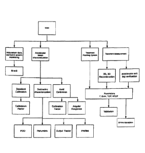
More concretely and according to figure 1, the methodology of the invention
starts from an initial
state (1) allowing the user to select the beginning of a methodology
application among the three
possible ones: data acquisition, control and monitoring of the system (2);
characterization of the
accelerator beam (6); and verification of the treatment (18). The
characterization of the accelerator
beam allows selecting the beginning of the procedure to calibrate in standard
conditions (7), a
dosimetric characterization (12) and an axial characterization (9) of a
detection medium. From the
standard calibration we get the calibration factor (8), whereas from the axial
calibration (9) we get
a calibration factor (10) and the angular response (11), getting in line a
dosimetric characterization
(12) from which the PDD (13); the penumbra (Fig. 3 or 144) and the output
factor (15); and the
profiles (26) are obtained. The verification (18), prior measurement of the
treatment in the axial
system, allows access to the 3D reconstruction (19) based on such measurements
(16), to the TPS
calculation (5), and to the results of the accelerator logs (17) after
supplying the measured
treatment, allowing access to the parameters (19), of validation (18),
validating (19) or correcting
mistakes (25), if the parameters do not meet the established criteria as being
safe for the treatment.
Regarding the procedure to verify radiotherapy treatments, the method and
system allow collecting
automated data for every angular position of the detection medium and for the
information
included in the accelerator logs, in order to later visualize the
reconstruction of the dose map and
the parameters calculation that allow its verification, as non-limiting
example, the gamma index.
The method gives the user the possibility to select the cGy/UM relation
according to the accelerator
.. energy. The method allows obtaining the dose calibration factor under
standard conditions and
reference conditions; the tables relating to the available dose profile; the
calculation of the
percentage depth-dose inside the mediums for the user; visualizing the
calculation of the penumbra
obtained with the semiconductor detector medium, applying the methodology and
the output factor
calculation.
11
CA 03033473 2019-02-08
Attorney Ref: 1379P002CA01
The method and system allow the user to visualize the axial characterization
with the detector
subsystem. The user may monitor the comparison between responses to the
different equal incident
angles (Fig. 6), and also visualize the data of the planner and the data
obtained for the detector
(Fig. 5), and the calibration factor for each angle as well as seeing the
final calibration (Fig. 7).
Fig. 9 shows a non-limiting example of the algorithm application for the dose
map reconstruction
for a 32 strip detection medium, for a circular dose distribution (whose
circle is not in the middle)
with radius 3a (where a is the strip width). On the left it is shown the Y
axis projection or the dose
profile. On the right it is shown the dose distribution in the X, Y plane.
Finally. Fig. 10 shows a map with the result of the 2D gamma factor
calculation. The reference
file may be selected, as this is usually obtained by the planner, and the
reconstructed dose map file
to check the validity of the outcome.
12