Note: Descriptions are shown in the official language in which they were submitted.
CA 03033476 2019-02-08
WO 2018/075028 PCT/US2016/057700
VARIABLE ANGLE CUTTING GUIDE AND METHOD OF USING THE SAME
FIELD OF DISCLOSURE
[0001] The disclosure relates generally to tools and methods for orthopedic
medical
implant. More particularly, the disclosed subject matter relates to a cutting
guide and a method
of using such a cutting guide for cutting a bone in a surgery, for example,
for cutting bones of a
human foot in a total ankle replacement.
BACKGROUND
[0002] Orthopedic implant devices have been utilized to fully or partially
replace existing
skeletal joints in humans. During surgical procedures, bones need to be cut to
implant
orthopedic devices.
[0003] An ankle is a joint that acts much like a hinge. The ankle joint is
formed by the
union of three bones: a talus, a tibia and a fibula. The ankle bone is the
talus. The top of the
talus fits inside a socket that is formed by a lower end of the tibia, and the
fibula, the small bone
of the lower leg. Arthritis, bone degeneration, and/or injury can cause ankle
joint deterioration
resulting in pain, reduced range of motion, and decreased quality of life.
Options for treating the
injured ankle have included anti-inflammatory and pain medications, braces,
physical therapy,
joint arthrodesis, and total ankle replacement (or arthroplasty).
[0004] Total ankle replacement generally comprises two components ¨ a
tibial implant
and a talar implant. The implants comprise articulation surfaces sized and
configured to mimic
the range of motion of the ankle joint. For example, the talar implant may
comprise an implant
sized and configured to mimic the talar dome and the tibial implant may
comprise an articulation
surface sized and configured to mimic articulation of the tibia. An
articulating component may
be located between the talar implant and the tibial implant.
CA 03033476 2019-02-08
WO 2018/075028 PCT/US2016/057700
SUMMARY OF INVENTION
[0005] The present disclosure provides a cutting guide for cutting a bone
during a
surgical procedure. More particularly, the present disclosure provides a
cutting guide configured
to provide an adjustable angle, and a method for using the cutting guide, for
example, for cutting
a bone such as tibia in a surgery of total ankle arthroplasty. The present
disclosure also provides
a method of making the cutting guide. These include, but are not limited to,
the following
aspects and embodiments.
[0006] In one aspect, a cutting guide for cutting bone in a surgical
procedure is provided.
Such a cutting guide comprises a body and a rotatable device. In some
embodiments, the body
comprises a top portion, a bottom portion parallel to the top portion, and a
side portion
connecting the top and the bottom portions. The rotatable device is coupled to
one end of the top
portion of the body, and comprises a pivotal element and a handle. The handle
has a first portion
coupled to the pivotal element, and a second portion configured to be rotated
around an axis of
the pivotal element. Each of the top portion of the body, the side portion of
the body, the bottom
portion of the body, and the handle has one respective edge providing a
respective guide surface.
The body of the cutting guide is configured to be positioned against a first
bone and each
respective guide surface is configured to receive a surgical tool for cutting
the first bone.
[0007] In some embodiments, the axis of the pivotal element is
perpendicular to a plane
defined by the body of the cutting guide. The handle is movable at an angle,
for example, in the
ranee of from 0 to 60 degree, relative to an in-plane normal to the top
portion of the body of the
cutting guide. Each of the handle, the top portion of the body, the side
portion of the body and
the bottom portion of the body may have a surface being flat and coplanar to
one another. In
some embodiments, the body of the cutting guide and the handle defines a first
slot, with an
opening defined between the bottom portion of the body and the handle, when
the handle is in a
position away from the bottom portion of the body.
[0008] In some embodiments, the pivotal element comprises a device selected
from a
group consisting of a screw, a shoulder bolt, a dowel pin, a combination of a
bolt and a nut, a
wrenching device, a lock and gear device, and any combination thereof. The
body of the cutting
guide may define pin holes, for example, at least two pin holes. The pin holes
are sized and
configured to receive pins to couple the body to a bone. The handle may also
define at least one
pin hole, which is sized and configured to receive a pin to couple the handle
to a bone
2
CA 03033476 2019-02-08
WO 2018/075028 PCT/US2016/057700
[0009] The body and the rotatable device comprise a suitable material, for
example, -a
metal material such as stainless steel.
[0010] In some embodiments, the body of the cutting guide further defines a
second slot
in the upper or bottom portion of the body. The second slot has at least one
edge providing
respective guide surface, and is configured to receive a surgical tool for
cutting a second bone
during a surgical procedure.
[0011] In another aspect, a kit comprising a cutting guide as described
above and a
surgical tool is provided. The surgical tool is configured for cutting a bone
surface In some
embodiments, the surgical tool is selected from the group consisting of a high
speed burr, a saw,
an end cutting reamer and any combination thereof
[0012] In another aspect, a method for using the cutting guide described
above is also
provided. In some embodiments, the method comprises the following steps:
positioning the
cutting guide against a first bone of a patient so that the respective edges
provided by the body
and the handle match with a predetermined region of the first bone of the
patient; adjusting the
rotatable device so that the handle is oriented to a patient-specific angle
relative to the body of
the cutting guide; and cutting the first bone in the predetermined region
along the respective
edges of the body and the handle after the rotatable device is adjusted. In
some embodiments,
the cutting guide is used in a surgery of total ankle arthroplasty. The first
bone is tibia, and the
handle of the rotatable device is aligned along and covering a medial
malleolus.
[0013] In some embodiments, the method further comprises a step of fixing
the cutting
guide onto the first bone. The body of the cutting guide comprises at least
two pin holes, and the
cutting guide is coupled with the first bone by inserting at least two pins
into the at least two pin
holes. The method may also comprise a step of cutting a portion of a second
bone, for example
talus The body of the cutting guide further defines a second slot in the
bottom portion of the
body and the second slot matches a portion of the second bone to be cut.
[0014] The cutting guide provided in the present disclosure, which
comprises a rotatable
device with an adjustable handle, provides a variable patient-specific angle
according to a
patient's bone structure. For example, in a surgical procedure of total ankle
arthroplasty, the
handle can be oriented along and covering medial or lateral malleolus to keep
medial or lateral
malleolus intact while tibia is cut.
3
CA 03033476 2019-02-08
WO 2018/075028 PCT/1JS2016/057700
BRIEF DESCRIPTION OF THE DRAWINGS
[0015] The present disclosure is best understood from the following
detailed description
when read in conjunction with the accompanying drawings. It is emphasized
that, according to
common practice, the various features of the drawings are not necessarily to
scale. On the
contrary, the dimensions of the various features are arbitrarily expanded or
reduced for clarity.
Like reference numerals denote like features throughout specification and
drawings.
[0016] FIG. 1 illustrates an anatomic view of an ankle joint.
[0017] FIG. 2 is a plan view illustrating bones of an ankle joint.
[0018] FIG. 3 is a plan view illustrating a cutting guide in one
embodiment.
[0019] FIG. 4 is a plan view of an exemplary cutting guide with a rotatable
device in
accordance with some embodiments.
[0020] FIG. 5 is a perspective view of the cutting guide of FIG. 4.
[0021] FIG. 6 is a plan view of an exemplary cutting guide with a rotatable
device and
pin holes in accordance with some embodiments.
[0022] FIGS. 7-8 are plan views illustrating the cutting guide of FIG. 6
positioned
against a tibia and a fibula of a patient for cutting the tibia in some
embodiments.
[0023] FIG. 9 is a plan view illustrating an exemplary cutting guide with a
rotatable
device and a body defining a first slot and a second slot, for cutting a tibia
and a talus,
respectively, in accordance with some embodiments.
[0024] FIG. 10 illustrates the cutting guide of FIG. 9 positioned against a
tibia, a talus
and a fibula of a patient's left foot for cutting the tibia and the talus in
some embodiments.
[0025] FIG 11 is a plan view illustrating the cutting guide of FIG. 9
positioned against a
tibia, a talus and a fibula of a patient's right foot for cutting the tibia
and the talus in some
embodiments.
[0026] FIG. 12 is a plan view of another exemplary cutting guide with a
rotatable device
and pin holes in accordance with some embodiments.
[0027] FIG. 13 is a perspective view illustrating the cutting guide of FIG.
12.
[0028] FIG. 14 is a plan view illustrating another exemplary cutting guide
with a
rotatable device, pin holes and a body defining a first slot and a second
slot, for cutting a tibia
and a talus, respectively, in accordance with some embodiments.
4
CA 03033476 2019-02-08
WO 2018/075028 PCT/US2016/057700
[0029] FIG. 15 is a flow chart diagram illustrating an exemplary method of
using a
cutting guide as a part of a surgical procedure in accordance with some
embodiments.
DETAILED DESCRIPTION
[0030] This description of the exemplary embodiments is intended to be read
in
connection with the accompanying drawings, which are to be considered part of
the entire
written description. In the description, relative terms such as "lower,"
"upper,- "horizontal,"
"vertical,", "above," "below," "up," "down," "top" and "bottom" as well as
derivative thereof
(e.g., "horizontally," "downwardly," "upwardly," etc.) should be construed to
refer to the
orientation as then described or as shown in the drawing under discussion.
These relative terms
are for convenience of description and do not require that the apparatus be
constructed or
operated in a particular orientation. Terms concerning attachments, coupling
and the like, such
as "connected," refer to a relationship wherein structures are secured or
attached to one another
either directly or indirectly through intervening structures, as well as both
movable or rigid
attachments or relationships, unless expressly described otherwise.
[0031] In the present disclosure the singular forms "a," "an," and "the"
include the plural
reference, and reference to a particular numerical value includes at least
that particular value,
unless the context clearly indicates otherwise. When values are expressed as
approximations, by
use of the antecedent "about," it will be understood that the particular value
forms another
embodiment. As used herein, "about X" (where X is a numerical value)
preferably refers to
+10% of the recited value, inclusive. For example, the phrase "about 8"
preferably refers to a
value of 7.2 to 8.8, inclusive. Where present, all ranges are inclusive and
combinable. For
example, when a range of -1 to 5" is recited, the recited range should be
construed as including
ranges "Ito 4", "1 to 3", "1-2", "1-2 & 4-5", & 5", "2-5",
and the like. In addition, when a
list of alternatives is positively provided, such listing can be interpreted
to mean that any of the
alternatives may be excluded, e.g., by a negative limitation in the claims.
For example, when a
range of "1 to 5" is recited, the recited range may be construed as including
situations whereby
any of 1, 2, 3, 4, or 5 are negatively excluded; thus, a recitation of "1 to
5" may be construed as
"1 and 3-5, but not 2", or simply "wherein 2 is not included." It is intended
that any component,
element, attribute, or step that is positively recited herein may be
explicitly excluded in the
CA 03033476 2019-02-08
WO 2018/075028 PCT/US2016/057700
claims, whether such components, elements, attributes, or steps are listed as
alternatives or
whether they are recited in isolation.
[0032] In FIGS. 1-14, like items are indicated by like reference numerals,
and for brevity,
descriptions of the structure, provided above with reference to the preceding
drawings, are not
repeated.
[0033] The present disclosure provides a cutting or resection guide for
cutting a bone
during a surgical procedure. In accordance with some embodiments, a cutting
guide is
configured to provide an adjustable angle according to patient-specific bone
structure. The
cutting guide is used, for example, for cutting a bone such as tibia in a
surgery of total ankle
arthroplasty.
[0034] Referring to FIG. 1, an ankle joint 2 comprises a talus 4 in contact
with a tibia 6
and a fibula 8. A calcaneus 10 is located adjacent to the talus 4. In total
ankle replacements, the
talus 4 and the tibia 6 may be resected, or cut, to allow insertion of a talar
implant and a tibial
implant. Referring to FIG. 2, medial malleolus 12 is the medial surface of the
lower extremity of
tibia 6 prolonged downward. The talus (not shown) is below the tibia 6. Lower
extremity of the
fibula 8 is lateral malleolus. Different patients have different bone
structures including, for
example, medial malleolus 12 having different sizes and angles. It is desired
that medial
malleolus 12 is kept intact in total ankle replacement. Accidental cut or
damage should be
avoided.
[0035] Referring to FIG. 3, a cutting guide 14 in one embodiment comprises
a top
portion 16, a bottom portion 20, a side portion 18 connected with the top
portion 16, and a side
portion 19 connecting the top portion 16 and the bottom portion 20. The
cutting guide 14 defines
a slot 22 with an opening. the cutting guide 14 can be placed against a bone,
for example, a
tibia 6 of a patient. The portion or region of the bone within slot 22 of the
cutting guide 14 can
be cut by moving a cutting tool along at least some portions of -the edges of
the slot 22. In the
cutting guide 14, the top portion 16 and the side portion 18 may be oriented
at a fixed angle, for
example, 90 degree. However, different patients have various sized and angled
medial malleolus
12. So when cutting guide 14 is used for cutting a tibia 6, it might be
difficult to adjust and
match the fixed angle of cutting guide 14 with the angle of medial malleolus
12 of a patient.
Sometimes medial malleolus 12 could be partially damaged or even accidently
cut if careful
measure is not taken.
6
CA 03033476 2019-02-08
WO 2018/075028 PCT/US2016/057700
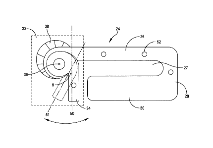
[0036] Referring to HG. 4, an exemplary cutting guide 24 with a rotatable
device 32 is
provided in accordance with some embodiments. Such a cutting guide 24
comprises a body 25
and a rotatable device 32. The body 25 comprises atop portion 26, a side
potion 28, and a
bottom portion 30. The bottom portion 30 may be parallel to the top portion
26. The side
portion 28 connects the top portion 26 and the bottom portion 30. The side
portion 28 may be
normal to the top and the bottom portions 26, 30 in some embodiments. The
rotatable device 32
is coupled to one end of the top portion 26 of the body 25. Such an end of the
top portion 26
may be opposite to the end connecting with side portion 28. The rotatable
device 32 comprises a
handle 34 and a pivotal element 36. The handle 34 has a first (or proximal)
portion 35 coupled
to the pivotal element 36, and a second (or distal) portion 37 configured to
be rotated around an
axis 40 of the pivotal element 36.
[0037] Referring to FIG. 5, axis 40 is at the center of pivotal element 36
and normal to a
top surface of the body 25 in some embodiments. The axis 40 of the pivotal
element 36 is
perpendicular to a plane defined by the body 25 of the cutting guide 24.
Referring to FIG. 4, the
handle 34 is movable at an angle (0) as shown in FIG. 4, relative to an in-
plane normal 50 to the
top portion 26 of the body 25 of the cutting guide 24. The handle 34 may have
an axis 51 as
illustrated in FIG. 4. For example, such an angle (0) may be in the range of
from 0 to 60 degree
(e.g., from 0 to 30 degree or from 0 to 45 degree). When the angle is zero,
the second end 37 of
the handle 34 is perpendicular to the top portion 26 of the body 25. The
handle 34 is configured
to move in a plane parallel to the top surface of the body in some
embodiments.
[0038] Each of the top portion 26 of the body, the side portion 28- of the
body and the
bottom portion 30 of the body, and the handle 34 may have a surface being flat
and coplanar to
one another. Referring to FIG. 4, in some embodiments, the rotatable device 32
may optionally
comprise a support 38. Each of the top portion 26 of the body, the side
portion 28 of the body
and the bottom portion 30 of the body, and the support 38 of the rotatable
device 32 may have a
coplanar flat surface, or have a concave surface configured to be easily
placed against a bone.
[0039] Each of the top portion 26 of the body, the side portion 28 of the
body, the bottom
portion 30 of the body, and the handle 34 has one respective edge providing a
respective guide
surface. The respective edges for respective guide surface are labelled as
edges 42, 44, 46 and
48 as shown in FIG. 4 and FIG. 5. The body 25 of the cutting guide 24 is
configured to he
positioned against a first bone and each respective guide surface is
configured to receive a
7
CA 03033476 2019-02-08
WO 2018/075028 PCT/US2016/057700
surgical tool for cutting the first bone (for example, tibia 6). In some
embodiments, the body 25
of the cutting guide 24 and the handle 34 defines a first slot 27, with an
opening defined between
the bottom portion 30 of the body and the handle 34 as illustrated in FIG. 4,
when the handle 34
is in a position away from the bottom portion 30 of the body 25.
[0040] The pivotal element 36 comprises a device coupled with the handle
34. Examples
of a suitable device in the pivotal element 36 include but are not limited to
a screw, a shoulder
bolt, a dowel pin, a combination of a bolt and a nut, a wrenching device, a
lock and gear device,
and any combination thereof. The device for pivotal element 36 may be
continuously moved to
adjust the angle (0) and can self-lock when the desired angle is obtained. In
some other
embodiments, the device may be unscrewed for a suitable angle (0) and then
tightened. In some
embodiments, cutting guide 24 as illustrated in FIG. 4 and FIG. 5 may be sized
and configured to
be fit with and be fixed to an external jig or any other suitable means during
a surgery. In some
other embodiments, cutting guide 24 as illustrated in FIG. 4 and FIG. 5 may
comprise pinholes
52 as illustrated in FIG. 6.
[0041] Referring to FIG. 6, cutting guide 24 include pinholes 52 in
accordance with some
embodiments. For example, the body 25 of cutting guide 24 may define pin holes
52, for
example, at least two pin holes 52. The pin holes 52 are sized and configured
to receive pins to
couple the body 25 to a bone (by inserting pins into the pinholes 52 and the
bone), when the
cutting guide 24 is placed on or against a bone (as shown in FIG. 7). The
handle 24 may also
define at least one pin hole 52, which is sized and configured to receive a
pin to couple the
handle 34 to a bone during a surgical procedure.
[0042] The body 25 and the rotatable device 32 comprise a suitable
material, for
example, -a metal material such as stainless steel, or an engineering plastic
material or
combinations thereof The body 25 and the rotatable device 32 are made of
stainless steel in
some embodiments. The body 25 and the rotatable device 32 may comprise a
radiopaque
material.
[0043] Referring to FIG. 9, an exemplary cutting guide 54 comprises a
rotatable device
32 and a body 25 defining a first slot 27 and a second slot 29, for cutting a
first bone (e.g., a tibia
6) and a second bone (e.g., a talus 4), respectively, in accordance with some
embodiments.
Cutting guide 54 has the structural features as described above. The body 25
of the cutting guide
54 further defines the second slot 29 in the upper or bottom portion of the
body 25. The second
8
slot 29 has at least one edge 55 providing respective guide surface. Referring
to FIGS. 9 and 10
as discussed herein, the second slot 29 is configured to receive a surgical
tool for cutting the
second bone (e.g., a talus 4) during a surgical procedure.
[0044] Referring to FIGS. 12 and 13, another exemplary cutting guide 60 in
accordance
with some embodiments is illustrated. Cutting guide 60 has the structural
features of cutting
guide 24 as described above. In addition, the top portion 26 of the body 25 of
the cutting guide
60 defines additional features as shown used as an alignment tool, which help
orient the cut
guide 60 to an intramedullary guided rod (not shown). A general alignment
method for
preparing a total ankle replacement is described in INBONEO II Total Ankle
System Surgical
Technique, which is available from Wright Medical Group (Memphis, TN. Two
holes 62 on
either side are configured to fix the cutting guide 60 onto an external
fixture, which are attached
with two screws. Similar to holes 52 on cutting guide 24, at least two holes
64 are configured to
accept K-wires or pins for fixing the cutting guide 60 to a bone. The slots 66
and 68 are
configured to lighten the cutting guide and provide visibility during
fluoroscopy so that the
underlying bone and the cutting guide 60 and their position can be seen.
[0045] Referring to FIG. 14, another exemplary cutting guide 60 is
illustrated. Cutting
guide 60 of FIG. 14 has the structural features of cutting guide of FIGS. 12-
13 as described
above. Cutting guide 60 of FIG. 14 comprises a rotatable device 32 comprising
a handle 34 and
a pivotal element 36, holes 62, 64, and a body 25 defining a first slot 27. In
addition, the body
25 further defines a second slot 29. The two slots 27 and 29 are for cutting
two bones, for
example, a tibia and a talus, respectively, in accordance with some
embodiments.
[0046] In another aspect, the present disclosure provides a kit comprising
a cutting guide
as described above (24, 54, or 60) and a surgical tool for cutting a bone is
provided. The surgical
tool is configured for cutting a bone (by cutting through the surface). Such a
cutting guide (24,
54, or 60) comprises a body 25 and a rotatable device 32. The body 25
comprises a top portion
26, a side portion 28, and a bottom portion 30 parallel to the top portion.
The side portion 28
connects the top and the bottom portions 26, 28. The rotatable device 32 is
coupled to one end
of the top portion of the body, and comprises a pivotal element 36 and a
handle 34. The handle
34 has a first portion 35 coupled to the pivotal element 36 and a second
portion 37 configured to
be rotated around an axis 40 of the pivotal element 32. Each of the top
portion 26 of the body
25, the side portion 28 of the body 25, the bottom portion 30 of the body 25,
and the handle 34
9
Date Recue/Date Received 2020-05-26
has one respective edge providing a respective guide surface. The body 25 of
the cutting guide
(24, 54, or 60) may also define a second slot 29 in the bottom or upper
portion of the body. The
pivotal element 36 comprises a device selected from a group consisting of a
screw, a shoulder
bolt, a dowel pin, a combination of a bolt and a nut, a wrenching device, a
lock and gear device,
and any combination thereof. In some embodiments, the body 25 defines at least
two pin holes
52 sized and configured to receive pins to couple the body 25 of the cutting
guide to the bone.
The body 25 and the rotatable device 32 each comprise a suitable material such
as a metal (e.g.,
stainless steel). In some embodiments, the surgical tool is selected from the
group consisting of
a high speed burr, a saw, an end cutting reamer and any combination thereof.
[0047] Referring to FIG. 15, an exemplary method 70 of using a cutting
guide as a part of
a surgical procedure in accordance with some embodiments is illustrated.
[0048] At step 72, the cutting guide (e.g., 24, 54, or 60) as described
above is positioned
(or placed) against a first bone (e.g., tibia) of a patient so that the
respective edges provided by
the body 25 and the handle 34 match with a predetermined region of the first
bone of the patient.
The cutting guide can be also placed against a second bone having a portion to
be cut, or other
bones not to be cut. Preoperative assessment of the appropriate size and
position of the tibial and
talar components will provide intraoperative guidance. Preoperative templating
and radiographic
overlays can be used to estimate and identify the bone structure of a patient
and the
predetermined region or regions to be cut. Final implant size and position can
be determined
intraoperatively through direct visualization under fluoroscopic assistance.
General methods for
operation preparation and alignment in a total ankle replacement are described
in INBONEO II
Total Ankle System Surgical Technique.
[0049] The cutting guide (e.g., 24, 54, or 60) are aligned properly to
bones of a patient
including talus 4 and tibia 6, by defining six degrees of freedom including
three rotations and three
translations. The degrees of freedom for rotations include flexion/extension,
internal/external, and
varus/valgus. The degrees of freedom for translations include
anterior/posterior, medial/lateral,
and proximal/distal. The internal/external rotation can be determined from
medial/lateral malleoli
of the ankle joint 2. A surgeon may bisect the medial/lateral malleoli to
provide an angle, or use
an angle of the medial malleolus. An angle for
Date Recue/Date Received 2020-05-26
CA 03033476 2019-02-08
WO 2018/075028 PCT/US2016/057700
the flexion/extension rotation may be determined by referencing to tibia 6.
The cutting guide
(e.g., 24, 54, or 60) needs to be positioned so that the cut having a top
cutting line or surface (as
shown in FIGS. 7 and 8) is perpendicular to the center of the tibial axis in
some embodiments.
The varus/valgus rotation can be determined by placing the foot in the
plantigrade position and
making parallel cut aligned with a mechanical axis of tibia 6.
[0050] The translations for the cutting guide (e.g., 24, 54, or 60) may be
determined
through creating a cut to a damaged bone or bones while preserving the maximum
amount of
good bones. The medial/lateral position of the cut guide (e.g., 24, 54, or 60)
may be determined
by having a maximum tibial cut as allowable without interfering the medial
malleolus and fibula.
The proximal/distal placement of the cut guide (e.g., 24, 54, or 60) is
determined by removing a
minimum amount of bone for putting a minimal implant construct height. The
anterior/positioner
placement of the cutting guide may be necessary to ensure that the center of
rotation of the talus
4 is positioned underneath the tibia 6.
[0051] At step 72, the rotatable device 32 with handle 34 is adjusted so
that handle 34 is
oriented to a patient-specific angle relative to the body 25 of the cutting
guide. In embodiments,
an edge 48 of handle 34 is aligned with and parallel to the longitudinal axis
53 of the medial
malleolus 12. The edge 48 of handle 34 may be positioned laterally, medially
or along the same
longitudinal axis as the medial malleolus longitudinal axis 53. Referring to
FIG 4, for example,
the handle 34 is rotated at an angle (0) relative to an in-plane normal 50 to
the top portion 26 of
the body 25 of the cutting guide 24. Such an angle (0) may be in the range of
from 0 to 60
degree (e.g., from 0 to 30 degree or from 0 to 45 degree). Handle 34 is then
fixed or
automatically locks after step 72. In some embodiments, the pivotal element 36
may need to be
tightened depending on the mechanism of the rotatable device 32, for example,
if pivotal element
36 comprises a screw which may be loosened during step 72.
[0052] In some embodiments, the cutting guide (e.g., 24, 54, or 60) is used
in a surgery
of total ankle arthroplasty. The first bone is tibia 6. Tibial plateau as
shown for example, in
FIG. 7 and FIG. 8, is to be cut The medial malleolus is to be protected,
without any cutting or
damage. Referrina, to FIG. 7, the cutting guide 24 is placed over or against a
tibia 6 and a fibula
8 of a patient for cutting the tibia in some embodiments. The handle 34 of the
rotatable device
32 is aligned along and covering a medial malleolus 12. The side portion 28 of
the body 25 of
the cutting guide 24 is placed close to and/or covers the fibula 8, which is
not to be cut. The
11
CA 03033476 2019-02-08
WO 2018/075028 PCT/US2016/057700
shaded areas in FIG. 7 (and FIGS. 8, 10-11) illustrate the portions of the
bone(s) to be cut.
Referring to FIG. 8, the edge 48 of the handle 34 (illustrated with extension
dot line 55) is
parallel to the longitudinal axis 53 of the medial malleolus 12. In some
embodiments, the axis
51 of the handle 34 may be overlapped with or is proximal to the longitudinal
axis 53 of the
medial malleolus 12.
[0053] Referring to FIG. 10 and FIG. 11, the cutting guide 54 is placed
over or against a
talus 4, a tibia 6 and a fibula 8 of a patient for cutting the tibia 6 and the
talus 4 in some
embodiments. In FIG. 10 the cutting guide 54 is positioned against a tibia, a
talus and a fibula of
a patient's left foot. In FIG. 11, the cutting guide 54 is positioned against
a tibia, a talus and a
fibula of a patient's right foot.
[0054] The handle 34 of the rotatable device 32 is aligned with a
longitudinal axis 53 of
the medial malleolus 12. The side portion 28 of the body 25 of the cutting
guide 24 is placed
close to and/or covers the fibula 8, which is not to be cut. The tibia 6
falling within the first slot
27 (as shown in a shaded region) is to be cut for a space for a tibial
implant. The talus 4 falling
within the second slot 29 (shaded region) is to be cut for a space for a talar
implant. Cutting
tools are within the purview of those skilled in the art and include, but are
not limited to,
sawblades, reamers, drills, osteotomes, burrs and the like. It should be noted
that the tibial
implant and the talar implant are two component of a total ankle replacement.
[0055] At step 76, which is optional, the cutting guide (e.g., 24, 54, or
60) is fixed onto
the first bone. The body 25 of the cutting guide (e.g., 24, 54, or 60)
comprises at least two pin
holes (52 or 62 or 64). The cutting guide is coupled with the first bone by
inserting at least two
pins into the at least two pin holes.
[0056] At step 78, a portion of the first bone (e.g., tibia) is cut in the
predetermined
region along the respective edges of the body 25 and the handle 34 after the
rotatable device 32
is adjusted. Referring to FIGS. 7-8 and 10-11, the portion of the tibia 6
falling within the first
slot 27 is cut for a space for installing a tibial implant. The cutting can be
performed using a
suitable surgical tool Examples of a suitable surgical tool include but are
not limited to a high
speed burr, a saw, an end cutting reamer and any combination thereof
[0057] At step 80, a portion of a second bone, for example talus 4, is cut
in some
embodiments. This step is optional depending on the type of cutting guide. For
example, the
body of the cutting guide 54 further defines a second slot 29 in the bottom
portion 30 of the body
12
CA 03033476 2019-02-08
WO 2018/075028 PCT/US2016/057700
25 and the second slot 29 matches a portion of the second bone to be cut.
Referring to FIGS. 10
and 11, a portion of the talus 4 falling within the second slot 29 is cut for
a space for installing a
talar implant. The cutting can be performed using a suitable surgical tool-
Examples of a
suitable surgical tool include but are not limited to a high speed burr, a
saw, an end cutting
reamer and any combination thereof.
[0058] The present disclosure also provides a method of making the
cutting guide. The
cutting guide can be made using any suitable method. For example, the body and
the parts for
the rotatable device can be separately molded from a suitable material such as
stainless steel, and
then machined and assembled to form a resulting cutting guide
[0059] The cutting guide provided in the present disclosure comprises a
rotatable device
with an adjustable handle, and provides a variable patient-specific angle
according to a patient's
bone structure. In a surgical procedure of total ankle arthroplasty, the
handle can be oriented
along and covering medial or lateral malleolus to keep medial or lateral
malleolus intact while
either tibia or talus is cut.
[0060] Although the subject matter has been described in terms of exemplary
embodiments, it is not limited thereto. Rather, the appended claims should be
construed broadly,
to include other variants and embodiments, which may be made by those skilled
in the art.
* *
13