Note: Descriptions are shown in the official language in which they were submitted.
CA 03033538 2019-02-11
DATA COMMUNICATION METHOD AND DEVICE
TECHNICAL FIELD
[0001] Embodiments of this application relate to the field of
communications
technologies, and in particular, to a data communication method and a device.
BACKGROUND
[0002] During data communication in a wireless communications system,
data
received by a receiving end is usually different from data sent by a
transmitting end
due to a very complex propagation environment between the transmitting end and
the
receiving end.
[0003] In order that the receiving end can restore the data sent by the
transmitting
end, the transmitting end inserts a reference signal at a fixed location of a
resource
unit during data communication. Therefore, the receiving end can restore,
based on
the inserted reference signal, the data sent by the transmitting end.
[0004] In practice, in some cases, for example when the propagation
environment
is relatively ideal, a reference signal may be inserted into a small quantity
of resource
units to enable the receiving end to restore the data sent by the transmitting
end.
However, the reference signal cannot be flexibly configured in the manner of
inserting
a reference signal at a fixed location of a resource unit, thereby causing
excessive
overheads.
SUMMARY
[0005] Embodiments of this application provide a data communication
method
and a device, to resolve a problem that a reference signal cannot be flexibly
configured.
[0006] According to one aspect, an embodiment of this application
provides a
data communication method, including:
obtaining, by a terminal, first indication information or second indication
CA 03033538 2019-02-11
information, where the first indication information is used to indicate that a
reference
signal is carried in a resource unit, and the second indication information is
used to
indicate that no reference signal is carried in a resource unit, for example,
the terminal
receives the first indication information or the second indication information
from a
base station; and performing, by the terminal, data communication according to
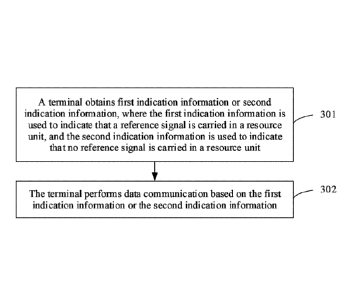
the
first indication information or the second indication information. Optionally,
the
reference signal is used for at least phase noise cancellation. The terminal
may
perform uplink data communication or downlink data communication with the base
station according to the first indication information or the second indication
information. Optionally, when the terminal performs downlink data
communication
according to the first indication information, the terminal performs phase
noise
cancellation based on the reference signal. In a solution of this embodiment
of this
application, the first indication information is used to indicate that a
reference signal
is carried in a resource unit, and the second indication information is used
to indicate
that no reference signal is carried in a resource unit. Therefore, the
reference signal is
properly configured, and this avoids a problem that overheads of the reference
signal
are excessively large or reference signals are significantly insufficient, so
that a
process in which the terminal and the base station perform data communication
according to the first indication information or the second indication
information is
reliable.
[0007] In a possible design, that the terminal receives the first
indication
information or the second indication information from a base station includes
one of
the following cases:
the terminal receives system information from the base station, where the
system information includes the first indication information or the second
indication
information; the terminal receives a radio resource control RRC message from
the
base station, where the RRC message includes the first indication information
or the
second indication information; or the terminal receives downlink control
information
DCI from the base station, where the DCI includes the first indication
information or
the second indication information, and the system information may be a system
information block or a master information block.
[0008] Optionally, the first indication information or the second
indication
information is carried in a first indication field.
[0009] Optionally, when the first indication information is carried in
the first
2
CA 03033538 2019-02-11
indication field, the system information, the RRC message, or the DCI further
includes at least one of the following indication fields: a second indication
field, used
to indicate an identifier of a reference signal sequence; a third indication
field, used to
indicate a time-frequency resource location of the reference signal; or a
fourth
indication field, used to indicate a port identifier of the reference signal.
[0010] Optionally, there is a correspondence between the port identifier
of the
reference signal and the identifier of the reference signal sequence. In this
case, when
the port identifier of the reference signal is obtained, the identifier of the
reference
signal sequence may be obtained based on the correspondence, or when the
identifier
of the reference signal sequence is obtained, the port identifier of the
reference signal
may be obtained based on the correspondence.
[0011] By receiving the system information, the RRC message, or the
downlink
control information sent by the base station, the indication information or
configuration information is sent by using an existing message. A
communication
method does not need to be changed. Therefore, this embodiment is compatible
with
the prior art, and is easy to operate and implement.
[0012] In a possible design, the obtaining, by a terminal, first
indication
information or second indication information includes: receiving, by the
terminal,
DCI from a base station, where the DCI includes information about a modulation
order and/or information about a quantity of scheduled resource blocks; and
obtaining,
by the terminal, the first indication information or the second indication
information
based on the information about the modulation order and/or the information
about the
quantity of scheduled resource blocks. Specifically, when the modulation order
is
greater than or equal to a preset modulation order and/or the quantity of
scheduled
resource blocks is greater than or equal to a preset quantity, the terminal
may obtain
the first indication information; or when the modulation order is less than a
preset
modulation order and/or the quantity of scheduled resource blocks is less than
a preset
quantity, the terminal may obtain the second indication information. Because
higher-order modulation is very sensitive to phase noise, and lower-order
modulation
is insensitive to phase noise, the reference signal for phase noise is not
required when
the modulation order is less than the preset modulation order. When the
quantity of
scheduled RBs is greater than the preset quantity, a gain brought by a phase
noise
pilot may be greater than a loss caused by overheads of the phase noise pilot.
Therefore, when the quantity of scheduled RBs is greater than the preset
quantity, the
3
CA 03033538 2019-02-11
phase noise pilot may be inserted for phase estimation.
[0013] In a possible design, the terminal may implicitly obtain the
configuration
information based on existing information. The following possible cases are
specifically included:
[0014] In a possible case, the terminal obtains the configuration
information of the
reference signal based on a correspondence between a CRC mask of a physical
broadcast channel PBCH and configuration information.
[0015] In another possible case, the terminal obtains the configuration
information
of the reference signal based on a correspondence between a physical cell
identifier
and configuration information.
[0016] In a possible design, the terminal sends capability information of
the
terminal to the base station, and the capability information is used to
indicate whether
the terminal has a capability of canceling phase noise. The base station
receives the
capability information, and generates the first indication information or the
second
indication information based on the capability information. The terminal sends
the
capability information to the base station. The base station generates the
first
indication information or the second indication information based on the
capability
information. Therefore, not only overheads of the phase noise pilot are
reduced, but
also it is ensured that downlink data finally obtained by the terminal is not
interfered
by the phase noise.
[0017] In a possible design, the terminal sends a configuration request
message of
a downlink reference signal to the base station. The configuration request
message is
used to request the base station to stop sending the downlink reference
signal, or is
used to request the base station to send the downlink reference signal. The
base station
receives the configuration request message, and the base station generates the
first
indication information or the second indication information based on the
configuration request message. The terminal sends the configuration request
message
to the base station. The base station generates the indication information
based on the
configuration request message. Therefore, not only overheads of the phase
noise pilot
are reduced, but also it is ensured that downlink data finally obtained by the
terminal
is not interfered by the phase noise.
[0018] In a possible design, reference signals may be further classified
into a
user-level reference signal and a cell-level reference signal, to be specific,
a user-level
phase noise pilot and a cell-level phase noise pilot. Optionally, for downlink
data
4
CA 03033538 2019-02-11
transmission, when a quantity of terminals in a preset range is less than a
first preset
quantity, a user-level phase noise pilot is used; or when a quantity of
terminals in a
preset range is greater than a second preset quantity, a cell-level phase
noise pilot is
used. The first preset quantity may be equal to the second preset quantity, or
the first
preset quantity may be less than the second preset quantity. The preset range
may be a
range covered by a physical cell.
[0019] According to another aspect, this application provides another
data
communication method, including: sending, by a base station, first indication
information or second indication information to a terminal, where the first
indication
information is used to indicate that a reference signal is carried in a
resource unit, and
the second indication information is used to indicate that no reference signal
is carried
in a resource unit; and performing, by the base station, data communication
according
to the first indication information or the second indication information.
Optionally, the
reference signal is used for at least phase noise cancellation. The base
station may
perform uplink data reception or downlink data transmission with the terminal
according to the first indication information or the second indication
information.
Optionally, when the base station performs uplink data reception according to
the first
indication information, the base station performs phase noise cancellation
based on
the reference signal. In a solution of this embodiment, the first indication
information
is used to indicate that a reference signal is carried in a resource unit, and
the second
indication information is used to indicate that no reference signal is carried
in a
resource unit. Therefore, the reference signal is properly configured, and
this avoids a
problem that overheads of the reference signal are excessively large or
reference
signals are significantly insufficient, so that a process in which the
terminal and the
base station perform data communication according to the first indication
information
or the second indication information is reliable.
[0020] In a possible design, the sending, by a base station, first
indication
information or second indication information to a terminal includes one of the
following cases: sending, by the base station, system information to the
terminal,
where the system information includes the first indication information or the
second
indication information; sending, by the base station, a radio resource control
RRC
message to the terminal, where the RRC message includes the first indication
information or the second indication information; or sending, by the base
station,
downlink control information DCI to the terminal, where the DCI includes the
first
5
CA 03033538 2019-02-11
indication information or the second indication information. For an indication
field
included in the system information, the RRC message, and the DCI, refer to the
foregoing description, and details are not described herein again.
[0021] According to still another aspect, an embodiment of this
application
provides a terminal, and the terminal can implement functions executed by the
terminal in the foregoing method embodiment. The functions may be implemented
by
using hardware, or may be implemented by hardware by executing corresponding
software. The hardware or the software includes one or more modules
corresponding
to the foregoing functions.
[0022] In a possible design, a structure of the terminal includes a
processor, and a
transmitter/receiver. The processor is configured to support the terminal in
performing
corresponding functions in the foregoing method. The transmitter/receiver is
configured to support communication between the terminal and a base station.
The
terminal may further include a memory. The memory is configured to be coupled
to
the processor. The memory stores a program instruction and data of the
terminal.
[0023] According to still another aspect, an embodiment of this
application
provides a base station, and the base station can implement functions executed
by the
base station in the foregoing method embodiment. The functions may be
implemented
by using hardware, or may be implemented by hardware by executing
corresponding
software. The hardware or the software includes one or more modules
corresponding
to the foregoing functions.
[0024] In a possible design, a structure of the base station includes a
processor,
and a transmitter/receiver. The processor is configured to support the base
station in
performing corresponding functions in the foregoing method. The
transmitter/receiver
is configured to support communication between base stations. The base station
may
further include a memory. The memory is configured to be coupled to the
processor.
The memory stores a program instruction and data of the base station.
[0025] According to still another aspect, an embodiment of this
application
provides a communications system. The system includes the base station and the
terminal described in the foregoing aspects.
[0026] According to yet another aspect, an embodiment of this application
provides a computer storage medium, configured to store a computer software
instruction used by the terminal. The computer software instruction includes a
related
program used for executing the foregoing aspect.
6
CA 03033538 2019-02-11
[0027] According to yet another aspect, an embodiment of this application
provides a computer storage medium, configured to store a computer software
instruction used by the base station. The computer software instruction
includes a
related program used for executing the foregoing aspect.
[0028] In comparison with the prior art, in the solution provided in the
embodiments of this application, the first indication information is used to
indicate
that a reference signal is carried in a resource unit, and the second
indication
information is used to indicate that no reference signal is carried in a
resource unit.
Therefore, the reference signal is properly configured, and this avoids a
problem that
overheads of the reference signal are excessively large or reference signals
are
significantly insufficient, so that a process in which the terminal and the
base station
perform data communication according to the first indication information or
the
second indication information is reliable.
BRIEF DESCRIPTION OF DRAWINGS
[0029] FIG. 1 shows a possible applicable application scenario according to
an
embodiment of this application;
[0030] FIG. 2 shows a possible applicable network architecture according
to an
embodiment of this application;
[0031] FIG. 3 is a schematic flowchart of Embodiment 1 of a data
communication
method according to an embodiment of this application;
[0032] FIG. 4 is a signaling flowchart 1 of Embodiment 1 of a data
communication method according to an embodiment of this application;
[0033] FIG 5 is a signaling flowchart 2 of Embodiment 1 of a data
communication method according to an embodiment of this application;
[0034] FIG. 6 is a signaling flowchart of Embodiment 2 of a data
communication
method according to an embodiment of this application;
[0035] FIG. 7 is a signaling flowchart of Embodiment 3 of a data
communication
method according to an embodiment of this application;
[0036] FIG. 8 is a signaling flowchart of Embodiment 4 of a data
communication
method according to an embodiment of this application;
[0037] FIG. 9 shows a possible schematic structural diagram of a related
terminal
according to an embodiment of this application;
7
CA 03033538 2019-02-11
[0038] FIG. 10 shows another possible schematic structural diagram of a
related
terminal according to an embodiment of this application;
[0039] FIG. 11 shows a possible schematic structural diagram of a related
base
station according to an embodiment of this application; and
[0040] FIG. 12 shows another possible schematic structural diagram of a
related
base station according to an embodiment of this application.
DESCRIPTION OF EMBODIMENTS
[0041] The following describes the technical solutions in the embodiments
of this
application with reference to the accompanying drawings in the embodiments of
this
application.
[0042] A network architecture and a service scenario described in the
embodiments of this application are intended to more clearly describe the
technical
solutions in the embodiments of this application, and do not constitute a
limitation on
the technical solutions provided in the embodiments of this application.
Persons of
ordinary skill in the art may learn that, with evolution of the network
architecture and
emergence of a new service scenario, the technical solutions provided in the
embodiments of this application are applicable to similar technical problems.
[0043] The following first describes a possible application scenario and
network
architecture in the embodiments of this application with reference to FIG. 1
and FIG 2.
[0044] FIG. 1 shows a possible applicable application scenario according to
an
embodiment of this application. As shown in FIG. 1, a terminal accesses an
operator
Internet Protocol (Internet Protocol, IP) service network such as a multimedia
subsystem (IP Multimedia System, IMS) network or a packet switched streaming
service (Packet Switched Streaming Service, PSS for short) network by using a
radio
access network (Radio Access Network, RAN) and a core network (Core Network,
CN). The technical solutions described in this application may be applied to a
Long
Term Evolution (Long Term Evolution, LTE) system, or other wireless
communications systems of various radio access technologies, for example, a
system
using an access technology such as Code Division Multiple Access (Code
Division
Multiple Access, CDMA), Frequency Division Multiple Access (Frequency Division
Multiple Access, FDMA), Time Division Multiple Access (Time Division Multiple
Access, TDMA), orthogonal frequency division multiple access (Orthogonal
8
CA 03033538 2019-02-11
Frequency Division Multiple Access, OFDMA), or a single carrier frequency
division
multiple access (Single Carrier Frequency Division Multiple Access, SC-FDMA).
In
addition, the technical solutions may further be applied to a subsequent
evolved
system of the LTE system, for example, a 5th Generation (5th Generation, 5G)
system.
For clarity, only the LTE system is used as an example herein for description.
In the
LTE system, an evolved universal terrestrial radio access network (Evolved
Universal
Terrestrial Radio Access Network, E-UTRAN) is used as a radio access network,
and
an evolved packet core (Evolved Packet Core, EPC) is used as a core network.
The
terminal accesses an IMS network by using the E-UTRAN and the EPC. It should
be
noted that a name of the base station and a name of the terminal may change
when the
solutions in the embodiments of this application are applied to the 5G system
or
another system that may occur in the future, but this does not affect
implementation of
the solutions in the embodiments of this application.
100451 In the embodiments of this application, a noun "network" and a
noun
"system" are usually used alternately, but persons skilled in the art may
understand a
meaning. A terminal related to the embodiments of this application may include
a
handheld device, an in-vehicle device, a wearable device, or a computing
device that
has a wireless communication function; another processing device connected to
a
wireless modem; or user equipment (User Equipment, UE) in various forms
including
a mobile station (Mobile Station, MS), a terminal device (terminal device),
and the
like. For ease of description, the devices mentioned above are collectively
referred to
as a terminal. A base station (Base station, BS) related to the embodiments of
this
application is an apparatus that is deployed in a radio access network and
that is
configured to provide a wireless communication function for a terminal. The
base
station may include a macro base station, a micro base station, a relay node,
an access
point, and the like in various forms. In systems using different radio access
technologies, names of devices having a function of a base station may vary.
For
example, the device is referred to as an evolved NodeB (evolved NodeB, eNB or
eNodeB) in a Long Term Evolution (Long Term Evolution, LTE) system, or
referred
.. to as a NodeB (NodeB) in a 3G communications system. For ease of
description, in
the embodiments of this application, all the foregoing apparatuses that
provide a
wireless communications function for the terminal are referred to as a base
station or a
BS.
100461 In the application scenario shown in FIG. 1, FIG. 2 shows a
possible
9
CA 03033538 2019-02-11
applicable network architecture according to an embodiment of this
application. The
network architecture mainly includes a base station 01 and a terminal 02.
Wireless
communication is performed between the base station 01 and the terminal 02.
[0047] The following further describes the embodiments of this
application in
detail based on common aspects mentioned in the foregoing embodiments of this
application.
[0048] In an existing solution, when data communication is performed
between a
base station and a terminal, a reference signal is fixedly inserted into a
resource unit.
In this way, a receiving end of data performs channel estimation, channel
detection,
phase noise estimation, and the like based on the reference signal, to restore
the data
sent by a transmitting end. The resource unit refers to a time-frequency
resource unit
used to carry data, for example, one or more resource blocks (Resource Block,
RB) or
one or more resource block groups (Resource Block Group, RBG). For example,
during downlink data transmission, the base station inserts a downlink
reference
signal into the resource unit, and when receiving a downlink signal that
includes the
downlink reference signal, the terminal may perform channel estimation,
channel
detection, phase noise estimation, and the like based on the downlink
reference signal,
to restore downlink data. Similarly, in uplink data reception, the base
station may also
restore uplink data based on an uplink reference signal.
[0049] However, in the existing solution of inserting a reference signal at
a fixed
location of a resource unit, the reference signal cannot be flexibly
configured. As a
result, in practice, overheads of the reference signal may be excessively
large, or
inserted reference signals are significantly insufficient, and consequently a
requirement of an actual propagation environment cannot be met.
[0050] In view of this, an embodiment provides a data communication method,
to
properly configure a reference signal. It should be noted that, in this
embodiment of
this application, the related reference signal may be used for at least one of
channel
estimation, channel detection, frequency offset estimation, phase noise
estimation, or
phase noise cancellation. Alternatively, the reference signal may be a
reference signal
specially used for channel estimation, a reference signal specially used for
channel
detection, a reference signal specially used for phase noise estimation, or a
reference
signal specially used for phase noise cancellation. The reference signal
specially used
for phase noise cancellation or a reference signal at least used for phase
noise
cancellation may also be referred to as a phase noise pilot. For ease of
description, in
CA 03033538 2019-02-11
methods shown in FIG. 3 to FIG. 8, the embodiments of this application are
described
by using a phase noise pilot as an example.
[0051] Specifically, for the phase noise pilot, in a wireless
communications
system, because a frequency processing component of a transmitting end is not
ideal,
an output carrier signal is not pure, and may carry phase noise. In a future
evolved
wireless system of the 3rd Generation Partnership Project (The 3rd Generation
Partnership Project, 3GPP for short), a used spectrum includes high frequency.
Therefore, to resolve phase noise generated due to high frequency, a receiving
end
uses the phase noise pilot to estimate the phase noise, and then compensates
for
impact of the phase noise to eliminate the phase noise.
[0052] FIG. 3 is a schematic flowchart of Embodiment 1 of a data
communication
method according to an embodiment of this application. As shown in FIG. 3, the
method includes:
[0053] S301. A terminal obtains first indication information or second
indication
information, where the first indication information is used to indicate that a
reference
signal is carried in a resource unit, and the second indication information is
used to
indicate that no reference signal is carried in a resource unit.
[0054] S302. The terminal performs data communication according to the
first
indication information or the second indication information.
[0055] The terminal in this embodiment obtains different indication
information
indicating whether a reference signal is carried in a resource unit. The
indication
information may be information predefined in a system, or may be indication
information received by the terminal from a base station, or may be indication
information received by the terminal from another network element. The
reference
signal may be an uplink reference signal or a downlink reference signal.
[0056] In an example, the first indication information or the second
indication
information may be carried in an information element. When the information
element
carries the first indication information, it indicates that a reference signal
is carried in
a resource unit. When the information element carries the second indication
information, it indicates that no reference signal is carried in a resource
unit. That is,
in this case, the information element may be used to indicate whether a
reference
signal is carried in a resource unit.
[0057] Optionally, in this embodiment, when at least one of the following
conditions is met, a reference signal needs to be carried in a resource unit.
The at least
11
CA 03033538 2019-02-11
one of the following conditions is specifically: The terminal or the base
station has a
capability of canceling phase noise; a modulation order of a modulation and
coding
scheme (Modulation and Coding Scheme, MCS) used in the system is less than a
preset modulation order; or a quantity of scheduled resource blocks is greater
than or
equal to a preset quantity.
[0058] Correspondingly, when at least one of following conditions is met,
no
reference signal is carried in a resource unit. The at least one of the
following
conditions is specifically: The terminal or the base station does not have a
capability
of canceling phase noise; a modulation order of an MCS used in the system is
greater
than or equal to a preset modulation order; or a quantity of scheduled
resource blocks
is less than a preset quantity. In this case, when the reference signal is not
required
during phase noise estimation, the reference signal is not inserted into the
resource
unit, thereby reducing overheads of the reference signal.
[0059] Persons skilled in the art may understand that higher-order
modulation is
very sensitive to phase noise, and lower-order modulation is insensitive to
phase noise.
When the quantity of scheduled RBs is greater than or equal to the preset
quantity, a
gain brought by a phase noise pilot may be greater than a loss caused by
overheads of
the phase noise pilot; or when the quantity of scheduled RBs is less than the
preset
quantity, a gain brought by a phase noise pilot may be less than a loss caused
by
overheads of the phase noise pilot.
[0060] In an example, when the terminal obtains the first indication
information,
the terminal may obtain configuration information. The configuration
information
includes the first indication information. The configuration information
further
includes time-frequency resource location information of the reference signal,
port
information of the reference signal, or sequence information of the reference
signal.
[0061] Specifically, the terminal may obtain the configuration
information in a
predefined manner, may receive the configuration information from the base
station,
or may obtain the configuration information from other information sent by the
base
station. A specific implementation in which the terminal obtains the
configuration
information is not limited herein in this embodiment.
[0062] The time-frequency resource location information of the reference
signal
includes a time-frequency resource location of the reference signal, or may
include a
location type of a time-frequency resource of the reference signal, to be
specific, each
location type corresponds to a time-frequency resource location. The time-
frequency
12
CA 03033538 2019-02-11
resource location may be a location of the reference signal in time domain
and/or
frequency domain. In an optional embodiment, the reference signal occupies one
or
more subcarriers. Correspondingly, the time-frequency resource location of the
reference signal may be a location of a scheduled subcarrier of the reference
signal in
frequency domain.
[0063] The sequence information of the reference signal includes a
reference
signal sequence; or may include an identifier of a reference signal sequence,
where
there is a correspondence between the identifier of the reference signal
sequence and
the reference signal sequence.
[0064] The port information of the reference signal includes an identifier
of a port
of the reference signal. The port of the reference signal is specifically an
antenna port,
and the identifier may be specifically a port number. The antenna port is
configured to
distinguish between resources in space, and different reference signals may be
transmitted on different antenna ports.
[0065] Specifically, when a reference signal is carried in a resource unit,
the
terminal obtains the first indication information. The first indication
information is
used to indicate that a reference signal is carried in a resource unit. Data
communication may be performed between the base station and the terminal
according to the first indication information. The data communication includes
uplink
data transmission and downlink data reception.
[0066] In an example, when the reference signal is a downlink reference
signal,
the terminal and the base station perform downlink data transmission according
to the
first indication information. Correspondingly, the terminal may perform phase
noise
cancellation based on the downlink reference signal, and a specific process
may be
shown in FIG. 4. When the reference signal is an uplink reference signal, the
base
station and the terminal perform uplink data transmission according to the
first
indication information. Correspondingly, the base station may perform phase
noise
cancellation based on the uplink reference signal, and a specific process may
be
shown in FIG. 5.
[0067] In methods shown in FIG. 4 and FIG. 5, an example in which the
terminal
receives the first indication information from the base station is used for
description.
[0068] FIG. 4 is a signaling flowchart 1 of Embodiment 1 of a data
communication method according to an embodiment of this application. FIG. 4
mainly describes a downlink data transmission process between a base station
and a
13
CA 03033538 2019-02-11
terminal. As shown in FIG. 4, the method includes:
[0069] S401. The base station sends first indication information to the
terminal.
[0070] The first indication information is used to indicate that a
downlink
reference signal is carried in a resource unit.
[0071] S402. The base station inserts a downlink reference signal into a
resource
unit.
[0072] S403. The base station and the terminal perform downlink data
transmission.
[0073] S404. The terminal performs phase noise cancellation based on the
downlink reference signal.
[0074] S402 to S404 are a process in which the base station and the
terminal
perform downlink data transmission according to the first indication
information. It
should be noted that S404 is an optional step.
[0075] FIG. 5 is a signaling flowchart 2 of Embodiment 1 of a data
communication method according to an embodiment of this application. FIG. 5
mainly describes an uplink data transmission process of a base station and a
terminal.
As shown in FIG. 5, the method includes:
[0076] S501. The base station sends first indication information to the
terminal.
[0077] The first indication information is used to indicate that an
uplink reference
signal is carried in a resource unit.
[0078] S502. The terminal inserts an uplink reference signal into a
resource unit.
[0079] S503. The base station and the terminal perform uplink data
transmission.
[0080] S504. The base station performs phase noise cancellation based on
the
uplink reference signal.
[0081] S502 to S504 are a process in which the base station and the
terminal
perform uplink data transmission according to the first indication
information. It
should be noted that S504 is an optional step.
[0082] When no reference signal is carried in a resource unit, the
terminal obtains
second indication information. The second indication information is used to
indicate
that no reference signal is carried in a resource unit. The base station and
the terminal
may perform data communication based on the second indication information. The
data communication includes uplink data transmission and downlink data
transmission. In this case, in a downlink data transmission process, the base
station
does not insert a phase noise pilot into the resource unit; and after
receiving a
14
CA 03033538 2019-02-11
downlink signal, the terminal does not perform a phase noise cancellation
operation.
In an uplink data transmission process, the terminal does not insert a phase
noise pilot
into the resource unit; and after receiving an uplink signal, the base station
does not
perform a phase noise cancellation operation. In this case, the phase noise
pilot does
.. not need to be inserted into the resource unit, so as to reduce
transmission overheads.
In addition, the base station or the terminal may not need to perform a phase
noise
cancellation operation, so as to simplify an operation of the base station or
the
terminal.
[0083] According to the data communication method provided in this
embodiment, the terminal obtains the first indication information or the
second
indication information. The first indication information is used to indicate
that a
reference signal is carried in a resource unit, and the second indication
information is
used to indicate that no reference signal is carried in a resource unit.
Therefore, the
reference signal is properly configured, and this avoids a problem that
overheads of
the reference signal are excessively large or reference signals are
significantly
insufficient, so that a process in which the terminal and the base station
perform data
communication according to the first indication information or the second
indication
information is reliable.
[0084] For the first indication information, the second indication
information, or
the configuration information in the foregoing embodiments, the following uses
an
example to describe a specific implementation in which the terminal obtains
the first
indication information, the second indication information, or the
configuration
information. Persons skilled in the art may understand that the first
indication
information, the second indication information, or the configuration
information in the
following may be first indication information, second indication information,
or
configuration information for downlink data transmission; or may be first
indication
information, second indication information, or configuration information for
uplink
data transmission. Refer to FIG. 5 for application of the first indication
information,
the second indication information, or the configuration information in the
uplink data
transmission process. Refer to FIG. 4 for application of the first indication
information,
the second indication information, or the configuration information in the
downlink
data transmission process. Details are not described herein again in this
embodiment.
[0085] In a specific embodiment, the base station may include the first
indication
information or the second indication information in another message sent to
the
CA 03033538 2019-02-11
terminal. The following feasible implementations may be specifically included:
[0086] In a feasible implementation, the base station sends system
information to
the terminal, and the terminal receives the system information from the base
station,
where the system information includes the first indication information or the
second
indication information. It should be noted that the system information may be
specifically a system information block (System Information Block, SIB for
short), or
may be a master information block (Master Information Block, MIB for short).
[0087] In another feasible implementation, the base station sends a radio
resource
control (Radio Resource Control, RRC for short) message to the terminal, and
the
terminal receives the RRC message from the base station, where the RRC message
includes the first indication information or the second indication
information.
[0088] In still another feasible implementation, the base station sends
downlink
control information (Downlink Control Information, DCI for short) to the
terminal,
and the terminal receives the DCI from the base station, where the DCI
includes the
.. first indication information or the second indication information.
[0089] Based on the foregoing feasible implementations, a first
indication field is
set in the system information, the RRC message, or the DCI information. The
first
indication information or the second indication information is carried in the
first
indication field. Specifically, the first indication field may be 1 bit (bit).
For example,
1 indicates that a phase noise pilot is inserted into a resource unit, and 0
indicates that
no phase noise pilot is inserted into a resource unit; or 1 indicates that no
phase noise
pilot is inserted into a resource unit, and 0 indicates that a phase noise
pilot is inserted
into a resource unit.
[0090] Optionally, when the first indication information is carried in
the first
indication field, the system information, the RRC message, or the DCI further
includes at least one of the following indication fields:
a second indication field, used to indicate an identifier of a reference
signal
sequence, where the identifier of the reference signal sequence may be, for
example,
an index (index) of the reference signal sequence;
a third indication field, used to indicate a time-frequency resource location
of a reference signal, where the time-frequency resource location of the
reference
signal may be indicated by using type information of the reference signal, for
example,
different types of reference signals correspond to different locations; or
a fourth indication field, used to indicate a port identifier of the reference
16
CA 03033538 2019-02-11
signal, where the port identifier of the reference signal may be, for example,
an index
of a port of the reference signal.
[0091] The
indication fields are separately described in the following by using
examples.
[0092] The second indication field is used to indicate the identifier of
the
reference signal sequence. Specifically, the identifier of the reference
signal sequence
may be, for example, 1, 2, or 3. If there are N (N is a natural number)
reference signal
N
sequences, log2 bits are
used to indicate an identifier of a reference signal
sequence.
[0093] The third indication field is used to indicate the time-frequency
resource
location of the reference signal. Specifically, it may be predefined that
there are N (N
is a natural number) types of time-frequency resource locations of reference
signals.
Each location type corresponds to a specific time-frequency resource location,
and
log2 N bi.ts are used to indicate a location type of a time-frequency
resource.
[0094] The fourth indication field is used to indicate the port identifier
of the
reference signal. Further, there is a correspondence between the port
identifier of the
reference signal and the identifier of the reference signal sequence. In this
case, when
the port identifier of the reference signal is obtained, the identifier of the
reference
signal sequence may be obtained based on the correspondence, or when the
identifier
of the reference signal sequence is obtained, the port identifier of the
reference signal
may be obtained based on the correspondence. Table 1 shows a feasible
correspondence.
Table 1
Identifier of a reference Reference signal sequence Port identifier of a
signal sequence reference signal
1 1, 1, 1, 1, 1, 1, 1, 1 7
2 1, 1,-1,-1, 1, 1,-1,-1 8
3 1,-1, 1,-1, 1,-1, 1,-1 9
4 1,-1, ¨1, 1, 1,-1,-1, 1 10
[0095] In this embodiment, the base station sends the system information,
the
17
CA 03033538 2019-02-11
RRC message, or the downlink control information to the terminal. The
indication
information or the configuration information is sent by using an existing
message, and
a communication method does not need to be changed. Therefore, this embodiment
is
compatible with the prior art, and is easy to operate and implement.
[0096] In another specific embodiment, based on the embodiment of FIG 3,
the
terminal may further obtain the first indication information or the second
indication
information based on information included in the downlink control information.
The
following provides detailed description with reference to FIG 6.
[0097] FIG. 6 is a signaling flowchart of Embodiment 2 of a data
communication
method according to an embodiment of this application. As shown in FIG. 6, the
method includes:
[0098] S601. A base station sends DCI to a terminal.
[0099] The DCI includes information about a modulation order and/or
information about a quantity of scheduled resource blocks.
[0100] S602. The terminal obtains first indication information or second
indication information based on information about a modulation order and/or
information about a quantity of scheduled resource blocks.
[0101] The DCI information includes at least the following content
elements:
resource block allocation information, and a modulation and coding scheme
(MCS).
The resource block allocation information includes the quantity of scheduled
resource
blocks. The MCS includes the modulation order. The modulation order includes
2, 4,
and 6. There is a correspondence between a modulation mode and a modulation
order.
For example, QPSK corresponds to a modulation order 2, 16QAM corresponds to a
modulation order 4, and 64QAM corresponds to a modulation order 4.
[0102] Specifically, the terminal may obtain the first indication
information by
using the following feasible implementations:
[0103] In a feasible implementation, when the modulation order is greater
than or
equal to a preset modulation order, the terminal obtains the first indication
information.
[0104] In another feasible implementation, when the quantity of scheduled
resource blocks is greater than or equal to a preset quantity, the terminal
obtains the
second indication information.
[0105] In still another feasible implementation, when the modulation
order is
greater than or equal to a preset modulation order, and the quantity of
scheduled
18
CA 03033538 2019-02-11
resource blocks is greater than or equal to a preset quantity, the terminal
obtains the
second indication information.
[0106] Correspondingly, the terminal may obtain the second indication
information by using the following feasible implementations:
[0107] In a feasible implementation, when the modulation order is less than
a
preset modulation order, the terminal obtains the second indication
information.
[0108] In another feasible implementation, when the quantity of scheduled
resource blocks is less than a preset quantity, the terminal obtains the
second
indication information.
[0109] In still another feasible implementation, when the modulation order
is less
than a preset modulation order, and the quantity of scheduled resource blocks
is less
than a preset quantity, the terminal obtains the second indication
information.
[0110] Optionally, the preset modulation order for the modulation order
and the
preset quantity for the quantity of scheduled RBs may be a default order or
quantity in
the system or may be predefined in the system, or may be sent by the base
station to
the terminal in advance by using various messages or signaling.
[0111] Persons skilled in the art may understand that when the terminal
obtains
the indication information based on the downlink control information, and when
the
base station sends system information, an RRC message, or the downlink control
information to the terminal, a first indication field does not need to be set
in an
indication field of each piece of information.
[0112] In this embodiment, the terminal implicitly obtains the first
indication
information or the second indication by using the downlink control
information. There
is no need to independently send information, existing information is
unchanged, and
no new information is added. Therefore, a process in which the terminal
obtains the
indication information is simple and easy to implement.
[0113] In a still another specific embodiment, the terminal may
implicitly obtain
configuration information based on existing information. The following
possible cases
are specifically included:
[0114] In a possible case, the terminal obtains the configuration
information of the
reference signal based on a correspondence between a cyclic redundancy check
(Cyclic Redundancy Check, CRC) mask of a physical broadcast channel (Physical
Broadcast Channel, PBCH) and configuration information.
[0115] Specifically, a broadcast channel (Broadcast Channel, BCH) is
mapped to
19
CA 03033538 2019-02-11
the PBCH after undergoing CRC, rate matching and channel coding, CRC mask
scrambling, and antenna mapping. Correspondingly, after receiving the PBCH,
the
terminal needs to obtain the BCH through demapping, descrambling, reverse CRC,
and the like. After the descrambling, the terminal may obtain the CRC mask. In
this
embodiment, there is a preset correspondence between a CRC mask and
configuration
information. Optionally, the CRC mask may indicate whether a reference signal
is
carried in a subframe. Different CRC masks correspond to different reference
signal
sequences, different CRC masks correspond to different time-frequency resource
locations of reference signals, and different CRC masks correspond to
different ports
of reference signals.
[0116] In another possible case, the terminal obtains the configuration
information
of the reference signal based on a correspondence between a physical cell
identifier
and configuration information.
[0117] Specifically, there are 504 physical cell identifiers (Physical
Cell Identifier,
PCI for short) in an LTE system. The terminal searches for a primary
synchronization
signal (Primary Synchronization Signal, PSS for short) and a secondary
synchronization signal (Secondary Synchronization Signal, SSS for short), and
combines the two signals to determine a specific physical cell identifier.
Optionally,
the physical cell identifier may correspondingly indicate whether a reference
signal is
carried in a subframe. When the physical cell identifier is a number
identifier, modulo
processing may be performed on the physical cell identifier based on a
quantity of
reference signal sequences, and different modulo results correspond to
different
reference signal sequences; or modulo processing may be performed on the
physical
cell identifier based on a quantity of location types of time-frequency
resources, and
different modulo results correspond to different time-frequency resource
locations.
[0118] In this embodiment, the configuration information is determined
based on
the CRC mask or the physical cell identifier. There is no need to
independently send
information, existing information is unchanged, and no new information is
added.
Therefore, a process in which the terminal obtains the configuration
information is
simple and easy to implement.
[0119] Based on the foregoing embodiment, in an application scenario in
which
the base station sends downlink data to the terminal, the terminal may further
send a
configuration indication to the base station, so that the base station can
generate
indication information of a downlink reference signal. Implementations shown
in FIG.
CA 03033538 2019-02-11
7 and FIG. 8 may be specifically included.
[0120] FIG. 7 is a signaling flowchart of Embodiment 3 of a data
communication
method according to an embodiment of this application. The method includes:
[0121] S701. A terminal sends capability information of the terminal to a
base
.. station.
[0122] The capability information is used to indicate whether the
terminal has a
capability of canceling phase noise.
[0123] S702. The base station generates first indication information or
second
indication information based on the capability information of the terminal.
[0124] Specifically, the terminal may directly send the capability message
to the
base station; or the capability information may be carried in an RRC message
sent by
the terminal to the base station, or may be carried in another message. The
capability
message is specifically used to indicate whether the terminal has a capability
of
canceling phase noise.
[0125] After receiving the capability message, the base station generates
configuration information based on the capability message, that is, whether
the base
station needs to insert a reference signal into a downlink resource unit.
[0126] When the capability message is used to indicate that the terminal
does not
have the capability of canceling phase noise, the base station generates the
second
indication message.
[0127] When the capability message is used to indicate that the terminal
has the
capability of canceling phase noise, the base station generates the first
indication
information.
[0128] In this embodiment, the terminal sends the capability information
to the
base station. The base station generates the first indication information or
the second
indication information based on the capability information. Therefore, not
only
overheads of a phase noise pilot are reduced, but also it is ensured that
downlink data
finally obtained by the terminal is not interfered by phase noise.
[0129] FIG. 8 is a signaling flowchart of Embodiment 4 of a data
communication
method according to an embodiment of this application. The method includes:
[0130] S801. A terminal sends a configuration request message of a
downlink
reference signal to a base station.
[0131] The configuration request message is used to request the base
station to
stop sending the downlink reference signal, or is used to request the base
station to
21
CA 03033538 2019-02-11
send the downlink reference signal.
[0132] S802. The base station generates first indication information or
second
indication information based on the configuration request message.
[0133] Specifically, the terminal may send the configuration request
message of
the downlink reference signal to the base station based on a demodulation
result of
downlink data. Specifically, if there is relatively large phase noise
interference in the
demodulation result, the configuration request message is used to request the
base
station to send the downlink reference signal. If there is no phase
interference in the
demodulation result, the configuration request message is used to request the
base
station to stop sending the downlink reference signal.
[0134] After receiving the configuration request message of the downlink
reference signal that is sent by the terminal, the base station generates the
indication
information based on the configuration request message. Specifically, if the
configuration request message is used to request the base station to send the
downlink
reference signal, the base station generates the first indication information.
If the
configuration request message is used to request the base station not to send
the
downlink reference signal, the base station generates the second indication
information.
[0135] In this embodiment, the terminal sends the configuration request
message
to the base station. The base station generates the indication information
based on the
configuration request message. Therefore, not only overheads of a phase noise
pilot
are reduced, but also it is ensured that downlink data finally obtained by the
terminal
is not interfered by phase noise.
[0136] Based on the foregoing embodiment, reference signals provided in
this
embodiment may further be classified into a user-level reference signal and a
cell-level reference signal, to be specific, a user-level phase noise pilot
and a cell-level
phase noise pilot. The user-level phase noise pilot is specific to one
terminal and used
by the terminal device to perform phase noise estimation. The cell-level phase
noise
pilot is specific to a plurality of terminals and used by terminals in a
physical cell to
perform phase noise estimation.
[0137] The cell-level phase noise pilot is carried in a downlink resource
unit, and
the user-level phase noise pilot may be carried in an uplink resource unit or
a
downlink resource unit. Both the cell-level phase noise pilot and the user-
level phase
noise pilot may be used. For example, the cell-level phase noise pilot is used
in a
22
CA 03033538 2019-02-11
downlink, and the user-level phase noise pilot is used in an uplink.
[0138] Further, for downlink data transmission, only one of the cell-
level phase
noise pilot and the user-level phase noise pilot is used. Specifically, when a
quantity
of terminals in a preset range is less than a first preset quantity, the user-
level phase
noise pilot is used; or when a quantity of terminals in a preset range is
greater than a
second preset quantity, the cell-level phase noise pilot is used. The first
preset quantity
may be equal to the second preset quantity, or the first preset quantity may
be less
than the second preset quantity. The preset range may be a range covered by a
physical cell.
[0139] In this embodiment, a system may use different phase noise pilots in
different scenarios, to achieve a balance between overheads and performance.
[0140] The foregoing describes the solutions provided in the embodiments
of this
application mainly from a perspective of interaction between the base station
and the
terminal. It may be understood that, to implement the foregoing functions, the
base
station and the terminal include a hardware structure and/or a software module
for
performing corresponding functions. With reference to units and algorithm
steps in
the examples described in the disclosed embodiments of this application, the
embodiments of this application may be implemented in a form of hardware or a
combination of hardware and computer software. Whether a function is performed
by
hardware or by computer software driving hardware depends on particular
applications and design constraint conditions of the technical solutions.
Persons
skilled in the art may use different methods to implement the described
functions for
each particular application, but it should not be considered that the
implementation
goes beyond the scope of the technical solutions in the embodiments of this
application.
[0141] In the embodiments of this application, the base station and the
terminal
may be divided into functional units based on the foregoing method examples.
For
example, the functional units may be obtained through division based on
corresponding functions, or two or more functions may be integrated into one
processing unit. The integrated unit may be implemented in a form of hardware,
or
may be implemented in a form of a software functional unit. It should be noted
that, in
the embodiments of this application, unit division is an example, and is
merely a
logical function division. In actual implementation, there may be another
division
manner.
23
CA 03033538 2019-02-11
[0142] When an integrated unit is used, FIG. 9 shows a possible schematic
structural diagram of a related terminal according to the foregoing
embodiments. A
terminal 100 includes a processing unit 12 and a communications unit 13. The
processing unit 12 is configured to control and manage an action of the
terminal. For
example, the processing unit 12 is configured to support the terminal in
performing
the processes S301 and S302 in FIG. 3, the processes S403 and S404 in FIG. 4,
the
processes S502 and S503 in FIG. 5, the process S602 in FIG. 6, the process
S701 in
FIG. 7, and the process S801 in FIG. 8 and/or another process of a technology
described in this specification. The communications unit 13 is configured to
support
communication between the terminal and a base station. The terminal may
further
include a storage unit 11, configured to store program code and data of the
terminal.
[0143] The processing unit 12 may be a processor or a controller, for
example, a
central processing unit (Central Processing Unit, CPU), a general-purpose
processor, a
digital signal processor (Digital Signal Processor, DSP), an application-
specific
integrated circuit (Application-Specific Integrated Circuit, ASIC), a field
programmable gate array (Field Programmable Gate Array, FPGA) or another
programmable logic component, a transistor logic component, a hardware
component,
or any combination thereof. The processing unit 12 may implement or perform
various example logical blocks, modules, and circuits that are described with
reference to the disclosed content of this application. The processor may also
be a
combination for implementing computing functions, for example, a combination
of
one or more microprocessors and a combination of a DSP and a microprocessor.
The
communications unit 13 is a transceiver, a transceiver circuit, or the like.
The storage
unit 11 may be a memory.
[0144] When the processing unit 12 is a processor, the communications unit
13
includes a transmitter and/or a receiver, and the storage unit 11 is a memory,
the
related terminal in this embodiment of this application may be the terminal
shown in
FIG. 10.
[0145] FIG. 10 shows a simplified schematic diagram of a possible design
structure of a related terminal according to an embodiment of this
application. A
terminal 200 includes a transmitter 21, a receiver 22, and a processor 23. The
processor 23 may also be a controller, and is represented as a
"controller/processor
23" in FIG. 10. Optionally, the terminal 200 may further include a modem
processor
25. The modem processor 25 may include an encoder 26, a modulator 27, a
decoder
24
CA 03033538 2019-02-11
28, and a demodulator 29.
[0146] In an example, the transmitter 21 adjusts (for example, performs
analog
conversion, filtering, amplification, and up-conversion) output sampling and
generates an uplink signal. The uplink signal is transmitted to the base
station in the
foregoing embodiments through an antenna. In a downlink, the antenna receives
a
downlink signal transmitted by the base station in the foregoing embodiments.
The
receiver 22 adjusts (for example, performs filtering, amplification, down-
conversion,
and digitization) a signal received from the antenna and provides input
sampling. In
the modem processor 25, the encoder 26 receives service data and a signaling
message that are to be sent in an uplink, and processes the service data and
the
signaling message (for example, performs formatting, encoding, and
interleaving).
The modulator 27 further processes (for example, performs symbol mapping and
modulation) encoded service data and an encoded signaling message, and
provides
output sampling. The demodulator 29 processes (for example, performs
demodulation)
the input sampling, and provides symbol estimation. The decoder 28 processes
(for
example, performs de-interleaving and decoding) the symbol estimation, and
provides
decoded data and a decoded signaling message that are to be sent to the
terminal 200.
The encoder 26, the modulator 27, the demodulator 29, and the decoder 28 may
be
implemented by the combined modem processor 25. The units perform processing
based on a radio access technology (for example, access technologies of LTE
and
another evolved system) used in a radio access network. It should be noted
that, when
the terminal 200 does not include the modem processor 25, the foregoing
functions of
the modem processor 25 may also be completed by the processor 23.
[0147] The processor 23 controls and manages an action of the terminal
200, and
is configured to execute a processing process performed by the terminal 200 in
the
foregoing embodiments of this application. For example, the processor 23 is
further
configured to perform the processes S301 and S302 in FIG. 3, the processes
S403 and
S404 in FIG. 4, the processes S502 and S503 in FIG. 5, the process S602 in
FIG. 6, the
process S701 in FIG. 7, and the process S801 in FIG. 8 and/or another process
of the
technical solutions described in this application.
[0148] Further, the terminal 200 may further include a memory 24. The
memory
24 is configured to store program code and data of the terminal 200.
[0149] When an integrated unit is used, FIG. 11 shows a possible
schematic
structural diagram of a related base station according to the foregoing
embodiments. A
CA 03033538 2019-02-11
base station 300 includes a processing unit 32 and a communications unit 33.
The
processing unit 32 is configured to control and manage an action of a
terminal. For
example, the processing unit 32 is configured to support the base station in
performing the processes S401 to S403 in FIG. 4, the processes S501, S503, and
S504
.. in FIG. 5, the process S601 in FIG. 6, the process S702 in FIG. 7, and the
process S802
in FIG. 8 and/or another process of a technology described in this
specification. The
communications unit 33 is configured to support communication between the base
station and a terminal. In addition, the communications unit 33 may further
support
communication between the base station and another network entity, for
example, a
mobility management entity (Mobility Management Entity, MME) and a serving
gateway (Serving Gateway, SGW). The base station may further include a storage
unit
31, configured to store program code and data of the base station.
101501 The processing unit 32 may be a processor or a controller, for
example, a
central processing unit (Central Processing Unit, CPU), a general-purpose
processor, a
digital signal processor (Digital Signal Processor, DSP), an application-
specific
integrated circuit (Application-Specific Integrated Circuit, ASIC), a field
programmable gate array (Field Programmable Gate Array, FPGA) or another
programmable logic component, a transistor logic component, a hardware
component,
or any combination thereof. The processing unit 32 may implement or perform
.. various example logical blocks, modules, and circuits that are described
with
reference to the disclosed content of this application. The processor may also
be a
combination for implementing computing functions, for example, a combination
of
one or more microprocessors and a combination of a DSP and a microprocessor.
The
communications unit 33 may include a transceiver, a transceiver circuit, a
.. communications interface, and the like. The storage unit 31 may be a
memory.
[0151] When the processing unit 32 is a processor, the communications
unit 33
includes a transmitter and/or a receiver, and the storage unit 31 is a memory,
the
related base station in this embodiment of this application may be a base
station
shown in FIG. 12. The transmitter and/or the receiver may be represented as a
.. "transmitter/receiver".
[0152] FIG. 12 shows another possible schematic structural diagram of a
related
base station according to an embodiment of this application.
[0153] A base station 400 includes a transmitter/receiver 41 and a
processor 42.
The processor 42 may also be a controller, and is represented as a
26
CA 03033538 2019-02-11
"controller/processor 42" in FIG. 12. The transmitter/receiver 41 is
configured to
support the base station in sending and receiving information to/from the
terminal in
the foregoing embodiments, and support radio communication between the
terminal
and another terminal. The processor 42 performs various functions of
communicating
.. with the terminal. In an uplink, an uplink signal from the terminal is
received via an
antenna, and is demodulated by the receiver 41 (for example, a high-frequency
signal
is demodulated to obtain a baseband signal). Further, the processor 42
performs
processing to restore service data and signaling information sent by the
terminal. In a
downlink, service data and a signaling message are processed by the processor
42,
and are modulated by the transmitter 41 (for example, a baseband signal is
modulated
to obtain a high-frequency signal) to generate a downlink signal. The downlink
signal
is transmitted to the terminal via the antenna. It should be noted that the
foregoing
demodulation or modulation function may also be completed by the processor 42.
For
example, the processor 402 is further configured to perform the processes S401
to
S403 in FIG. 4, the processes S501, S503, and S504 in FIG. 5, the process S601
in FIG.
6, the process S702 in FIG. 7, and the process S802 in FIG. 8 and/or another
process
of the technical solution described in this application.
[0154] Further, the base station 40 may further include a memory 43. The
memory
43 is configured to store program code and data of the base station 40. In
addition, the
base station may further include a communications interface 44. The
communications
interface 44 is configured to support communication between the base station
and
another network entity (for example, a network device in a core network). For
example, in an LTE system, the communications unit 44 may be an Si-U
interface,
and is configured to support communication between the base station and an
SGW; or
the communications unit 44 may be an S 1 -MME interface, and is configured to
support communication between the base station and an MME.
[0155] It may be understood that FIG. 12 shows only a simplified design
of the
base station 400. In actual application, the base station 400 may include any
quantity
of transmitters, receivers, processors, controllers, memories, communications
units,
.. and the like. All base stations that can implement this embodiment of this
application
fall within the protection scope of this embodiment of this application.
[0156] Methods or algorithm steps described in combination with the
content
disclosed in the embodiments of this application may be implemented by
hardware, or
may be implemented by a processor by executing a software instruction. The
software
27
CA 03033538 2019-02-11
instruction may include a corresponding software module. The software module
may
be stored in a random access memory (Random Access Memory, RAM for short), a
flash memory, a read-only memory (Read Only Memory, ROM), an erasable
programmable read only memory (Erasable Programmable ROM, EPROM), an
electrically erasable programmable read only memory (Electrically EPROM,
EEPROM), a register, a hard disk, a removable hard disk, a compact disc read-
only
memory (CD-ROM), or any other form of storage medium well-known in the art.
For
example, a storage medium is coupled to the processor, so that the processor
can read
information from the storage medium or write information into the storage
medium.
Certainly, the storage medium may be a component of the processor. The
processor
and the storage medium may be located in the ASIC. In addition, the ASIC may
be
located in a base station or a terminal. Certainly, the processor and the
storage
medium may exist in a base station or a terminal as discrete components.
[0157] Persons skilled in the art should be aware that in the foregoing
one or more
examples, functions described in the embodiments of this application may be
implemented by hardware, software, firmware, or any combination thereof. When
the
functions are implemented by software, the functions may be stored in a
computer-readable medium or transmitted as one or more instructions or code in
the
computer-readable medium. The computer-readable medium includes a computer
storage medium and a communications medium, where the communications medium
includes any medium that enables a computer program to be transmitted from one
place to another. The storage medium may be any available medium accessible to
a
general-purpose or dedicated computer.
[0158] Persons of ordinary skill in the art may understand that all or
some of the
steps of the method embodiments may be implemented by a program instructing
relevant hardware. The program may be stored in a computer-readable storage
medium. When the program runs, the steps of the method embodiments are
performed.
The foregoing storage medium includes: any medium that can store program code,
such as a ROM, a RAM, a magnetic disk, or an optical disc.
[0159] Finally, it should be noted that the foregoing embodiments are
merely
intended for describing the technical solutions of this application other than
limiting
this application. Although this application is described in detail with
reference to the
foregoing embodiments, persons of ordinary skill in the art should understand
that
they may still make modifications to the technical solutions described in the
foregoing
28
CA 03033538 2019-02-11
embodiments or make equivalent replacements to some or all technical features
thereof, without departing from the scope of the technical solutions of the
embodiments of this application.
29