Note: Descriptions are shown in the official language in which they were submitted.
I
TITLE
TENSIONING DEVICE
FIELD OF INVENTION
This invention relates generally to chain binders and, in particular, to a
chain binders for use in
the transportation industry, to secure cargo in position during
transportation.
BACKGROUND
A chain binder is a device, used in the transportation industry, to tension
chains passing over,
around or through a load to secure it in position while being transported. The
binder is installed
between two points on the chain, between the chain and anchor point, and/or
directly to the
object being secured.
There are a number of binder types conventionally used for tensioning and
lashing devices such
as chains, cables, and straps, that secure loads being transported by trucks,
ships, aircraft or
rail. Most of these binders have inherent operating safety problems since they
require
substantial physical and repetitive effort, and/or require the operator to be
on the deck of the
vehicle or in other awkward positions while they are being installed or
tensioned.
Lever type binders have little lengthwise adjustment and require the operator
to apply excessive
physical effort to close the binder and this can result in physical injury.
The handles have a
tendency to spring back, injuring the operator or nearby personnel, especially
if an extension
bar is being used on the lever handle to close it. Also, operation of the
binder can over-stress
and damage the lashings due to the excessive forces applied. It is now common
for
transportation companies and their customers to ban lever binder use on their
vehicles or their
premises. Lever binders can spring open if not properly fully closed, thus
loosening the lashing
during transport and now, laws specifically require the handles to be secure
in position.
Double screw ratchet binders require the operator to ratchet a handle while
applying a
considerable force to the handle to achieve proper lashing tension. Injury to
the user's
shoulders, arms, wrists and back associated with this operation is common,
especially when a
significant number of the binders are in use, operated repetitively, and where
access to the
binder is awkward, due its position or orientation.
CA 3033751 2021-05-15
2
Power operated binders are now available, however, they are generally ratchet-
style binders
with a gearbox in place of the ratchet handle or in addition to the handle. A
power unit, at the
center of the binder, drives the binders through the gearing mounted in the
middle of a rotating
tube, which screws on to threaded eye bolts, one at either end, thus drawing
the eye bolts and
hooks together. The truck driver must reach into the center, and usually at a
right angle, to
engage the power driver to the gearing of this type of binder. The threaded
tube with the gear
housing tends to rotate when power is applied to the binder. This rotation
requires the operator
to apply a force to counteract rotational torque and this is very difficult
for the truck driver while
standing on the ground and reaching into the middle of the binder.
Current lever, ratchet and power binders use chain links to connect the hooks
to the ends of the
binder and the operator must gasp the hook to orient and engage it with the
chain. In many
cases the operator will not have an adequate reach to engage the hook while
standing beside
the vehicle and will elect, if practicable, to install and tension the binder
from a location on the
deck, The operator is often in an unstable position at the edge of the vehicle
while tensioning
these binders. Also, while walking on the truck deck, he is exposed to
tripping hazards such as
binders, lashing and cribbing that is already in place or lying on the deck,
or the cargo itself. In
numerous cases truck drivers have fallen from the truck deck to the ground and
been seriously
injured.
Thus, there is a need for a binder that can reduce physical hazards when used
relative to
current binders and that can facilitate the safe efficient installation,
tensioning of a chain, and
securing of a cargo with minimal effort.
SUMMARY
In one embodiment, the present disclosure provides a tensioning device for
tensioning chains to
secure loads on a transport vehicle, the tensioning device comprising: a first
and second U-
shaped yoke each comprising two parallel arms, the arms being joined at one
end by a member
forming a bottom member of the U, and the arms are open at an other end, the
parallel arms
each have a hole positioned proximate the open end of each arm, the holes
dimensioned to
accept a pin passing through both holes, the bottom member of the first U-
shaped yoke having
a threaded hole extending therethrough on a center line of the first yoke, the
bottom member of
the second U-shaped yoke having an unthreaded hole; a threaded bolt rotatably
extending
through the unthreaded hole in the bottom member of the second yoke and
engageably
CA 3033751 2021-05-15
3
extending through the threaded hole in the bottom member of the first yoke,
the threaded bolt
engaging with threads in the threaded hole in the first yoke and coupling the
second U-shaped
yoke to the first U-shaped yoke; a first fitment for coupling to a chain, the
first fitment pivotably
coupled to the first U-shaped yoke with a first clevis pin extending through
the holes in the arms
of the first U-shaped yoke; and a second fitment pivotably coupled to the
second U-shaped yoke
with a second clevis pin, a rotation limiter with a limiter leg, the limiter
being secured to one of or
between the parallel arms of the first U-shaped yoke at the open end, the leg
extending to limit
rotation of the first fitment relative to the first U-shaped yoke; a drive
assembly comprising a
universal type joint releasably coupleable with a head of the threaded bolt to
the socket, and an
extension bar extending from the universal type joint; wherein actuating the
extension bar of the
drive assembly rotates the threaded bolt, which moves the first U-shaped yoke
away or towards
the second U-shaped yoke
In some examples, the first fitment is a first hook for hooking a chain, the
first hook pivotably
coupled to the first U-shaped yoke with the first clevis pin extending through
the holes in the
arms of the first U-shaped yoke; and the second fitment is a second hook
pivotably coupled to
the second U-shaped yoke.
In some examples, the tensioning device further comprises a swivel assembly
pivotably coupled
to the second U-shaped yoke with the second clevis pin extending through the
holes in the arms
of the second U-shaped yoke; the second hook being pivotably coupled to the
swivel assembly
with a third clevis pin.
In some examples, the swivel assembly comprises: a swivel yoke having a pair
of short arms
connected by a bottom member at one end, the bottom member of the swivel York
having
another hole extending therethrough; a swivel fixture having one end of which
is a tang drilled in
the center to receive the third clevis pin therethrough and configured to
allow the second hook
to pivot around the third clevis pin, and an opposite end being a threaded
member dimensioned
to pass through the other hole in the bottom member of the swivel yoke; a
swivel nut; wherein,
the threaded end of the swivel fixture extends through the bottom member of
the swivel yoke,
engages the swivel nut positioned between the short arms of the swivel yoke
and allows the
swivel fixture and the second hook pinned to the tang to rotate within the
swivel yoke.
In some examples, the extension bar is a ratchet-type extension bar, and the
universal type joint
is a gimbal or wobble type joint, and the socket is a drive socket compatible
with the head of the
bolt.
CA 3033751 2021-05-15
4
In some examples, the tensioning device further comprises an external power
driver, a ratchet
handle, or crank operatively coupled to the extension bar, the external power
driver, ratchet
handle, or crank configured to transfer a rotational force through the drive
assembly, which
rotates the threaded bolt to which it is engaged.
In some examples, the extension bar has a length such that the external power
driver, ratchet
handle, or crank is positioned at a distance from the bolt head.
In some examples, the drive assembly comprises a socket that is compatible
with the head of
the threaded bolt, the socket being releasably engagable between the head of
the threaded bolt
and the universal type joint.
In some examples, the threaded bolt has a socket head that is compatible with
the wobble or
universal joint.
In some examples, the limiter leg is positioned under the arm of the first U-
shaped york, the
limiter leg directed toward the centerline of the first yoke, extending past
both the first yoke arm
and a portion of the first hook, the limiter leg thereby restricting rotation
of the first hook around
the first clevis pin.
In some examples, the tensioning device further comprises a second rotation
limiter secured to
the other arm of the first U-shaped yoke.
In some examples, the tensioning device of further comprises a threaded washer
or nut secured
between the arms of the first U-shaped yoke, against the bottom member, on the
center line of
the first U-shaped yoke, to provide the threaded portion of the first yoke.
In some examples, the tensioning device of further comprises a rectangular
washer secured
between the arms of the first U-shaped yoke in the bottom member of the first
yoke.
In some examples, the first and or second fitments are engageable with cables,
nets, straps
and or anchor points pivotably coupled to the first U-shaped yoke, the second
U-shaped yoke or
the swivel tang with clevis pins.
In some examples, the universal joint is a the gimbal style joint and the
tensioning device further
comprises a socket head bolt that directly engages with the gimbal style
joint, and a
compressible, resilient disk mounted securely on a neck of the gimbal style
joint against the
body of the gimbal style joint between the body and the protrusion.
CA 3033751 2021-05-15
5
DESCRIPTION OF THE DRAWING
FIG. 1 is a plan view of a tensioning device according to an example
embodiment of the present
disclosure.
FIG. 2 is a side view of the tensioning device of Figure 1.
FIG. 3 is a plane view of a tensioning device according to another example
embodiment of the
present disclosure.
FIG. 4 is an illustration of multiple views of a main yoke in isolation.
FIG. 5 is an illustration of multiple view of a swivel yoke in isolation.
FIG. 6 is an illustration of multiple view of a swivel fitting in isolation.
FIG. 7 is a plan view of the tensioning device of FIG. 1 in use with a power
source.
FIG. 8 is a side view of FIG. 7.
FIG. 9 is a lower perspective view of a hook rotation limiter in isolation.
FIG. 10 is a side view of a user coupled the tensioning device of FIG. Ito a
chain on a truck.
FIG. 11 is a side view of the user of FIG. 10 using the tensioning device with
the power source
as shown in FIG. 8.
DETAILED DESCRIPTION
Binders are usually manufactured to comply with specifications laid down for
specific uses by
government, industrial associations and other users, such as Departments of
Transport, the
American Association of Railways. These specifications set out requirements
such as Working
Load Limits, Breaking Strength, lashing type and sizes (example - 5/16 grade 7
chain), etc. and
therefore, the dimensions, thread type, bolt style, thread length, materials
used, method of
manufacture, etc. are predicated by these requirements.
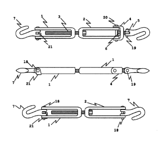
Turning to FIGS. 1 to 6, the tensioning device of the present disclosure
generally comprises two
opposing first and second yokes 1 and 2, connected by a fully threaded bolt 3.
A hook 7 and a
rotation limiter 21 are attached to the open end of first yoke 1 and a swivel
assembly 5 and
another hook 7 is connected to the end of second yoke 2.
First yoke 1 is a U shaped component, comprising two parallel arms, spaced
equally apart,
joined at one end by a member forming the bottom of the U, and open at the
other end (see
CA 3033751 2021-05-15
6
FIG. 4). A hole 9a on the center line of yoke 1, extending through the bottom
member, is
threaded for engagement with bolt 3. Two symmetrical holes 8a extend through
the ends of the
arms, at the open end of yoke 1, and are dimensioned to accept a clevis pin
18. Clevis pin 18
also passes through clevis holes of in hook 7, which is located between the
arms of yoke 1. The
length of the arms of yoke 1 are of sufficient length to allow bolt 3 to be
extend between the
arms of yoke 1 while also not contacting clevis pin 18. If hole 9a in the
bottom of yoke 1
insufficient to provide adequate thread engagement with bolt 3, an appropriate
nut or threaded
washer may be installed in the bottom of yoke 1, between the arms, to provide
the required
threads. For example, a rectangular washer in the bottom of yoke 1 can be used
under the nut
to assist in transferring forces from bolt 3 to the yoke arms. The distance
between the arms is
greater than the diameter of bolt 3 and is also sufficiently wide to allow
hook 7 to fit between the
arms.
Second yoke 2 is also a U shaped component, similar to yoke 1 with hole 9a
extending through
the bottom member. In this case, hole 9a in the bottom member of yoke 2 is
slightly larger than
the diameter of bolt 3 and is not threaded. This allows bolt 3 to pass through
second yoke 2
without engaging with hole 9a in yoke 2. The surface of yoke 2 where a head of
bolt 3 bears
against yoke 2 must be made to properly seat the bolt head without binding
when rotated. A
washer can be used between the bolt head and the bottom of yoke 2 to reduce
friction and
torque that may be required to rotate bolt 3 and distribute forces from bolt 3
into the arms of
yoke 2. The two holes 8a at the open end of the arms of yoke 2 accept another
clevis pin 18. In
FIGS. 1 and 2, this clevis pin 18 also passes through clevis holes in swivel
yoke 4. In FIG. 3,
this clevis pin 18 also passes through hook 7 between the yoke arms when
swivel yoke 4 is not
in use. The distance between the arms of yoke 2 must be greater than a
universal joint 17 and a
socket 16 (described further below) to allow them to pass between the arms of
yoke 2 and
engage with bolt 3. This distance must also be sufficiently wide to allow hook
7 to fit between
the arms when swivel yoke 4 is not in use.
A fully threaded bolt 3 passes through hole 9a in the bottom of yoke 2,
engages with hole 9a in
the bottom of yoke 1. When rotated, bolt 3 reduces the distance between yoke 1
and 2 and
thereby reduces the distance between the two attached hooks 7, thus tensioning
the chain to
which they are engaged. Bolt 3 must be of sufficient length to remain engaged
with yoke 1 when
the tensioning device is open and also be of sufficient length to eliminate
the slack in the chain
and tension the chain when bolt 3 is rotated. The head style, diameter, thread
type, and grade
of bolt 3 may be varied depending on the specifications to be meet. If a
socket head bolt is
CA 3033751 2021-05-15
7
used, the gimbal or wobble joint (described below) may be engaged directly
without socket 16
being required. Bolt 3 may also comprise of a threaded rod with a nut secured
to one end.
Swivel yoke 4 (see FIG. 5), is U shaped similar to yoke 2, with a hole 9b in
the bottom member
of swivel yoke 4 that is slightly larger than a threaded shaft 10 of a swivel
fitting 5 (discussed
below) through which threaded shaft 10 passes. Clevis pin holes 8b are
positioned at the open
end of swivel yoke 4 arms to accept a clevis pin 20 that secures swivel yoke 4
to second yoke 2.
The arms of swivel yoke 4 can be configured to be secured between or outside
of the arms of
yoke 2. The arms of swivel yoke 4 are of sufficiently length to ensure that
swivel fitting 5 and nut
6 do not interfere with clevis pin 20. A rectangular washer can be used
between nut 6 and
swivel yoke 4, to distribute the forces from swivel fitting 5 and the nut to
the arms of swivel
yoke 4.
Swivel fitting 5 (see FIG. 6) comprises one end in which is a semicircular
disc shaped
protrusion 13 with a hole 11 in the center of disc shaped protrusion 13. The
other end includes
threaded shaft 10, which passes through hole 9b in swivel yoke 4. Threaded
shaft 10 has a
sufficient length to fully engage nut 6, which is locked to the threads, while
also allowing swivel
fitting 5 to rotate in hole 9b. The protruding portion 13 may be separated
from threaded portion
by a washer or a washer shaped ridge 14, which acts as a bearing surface
against the
bottom of swivel yoke 4. Hole 11 in the center of protrusion 13 is dimensioned
to accept a hook
clevis pin 19, which pins hook 7 to protrusion 13 of swivel fitting 5 and
allows hook 7 to rotate
around the end of protrusion 13 and the center line of the tensioning device.
Swivel nut 6 functions to engage with threaded shaft 10 of swivel fitting 5
sufficiently to fully
engage the nut threads and is locked to it with sufficient thread left to
allow swivel fitting 5 to
freely rotate in swivel yoke 4 hole 9b.
Protrusion 13 on swivel fitting 5 may be a semi circular disk having central
hole 11 to accept
hook clevis pin 19, thereby attaching hook 7 to fitting swivel 5, and to allow
hook 7 to rotate
around hook clevis pin 19.
Washer 14 is an optional washer that may be disk shaped. Washer 14 is shown
positioned
between threaded shaft 10 and protrusion 13, which may bear against the bottom
of swivel
yoke 4.
Hooks 7 are example fitments. One hook 7 is attached to swivel fitting 5 with
clevis pin 19
through hole 11 in protrusion 13. Another hook 7 is attached to yoke 1 with
clevis pin 18
through holes 8a at the open end of the yoke arms that engage the chains to be
tensioned.
CA 3033751 2021-05-15
8
Holes 8a, 8b in the open end of the arms of first and second yokes 1, 2 and
swivel yoke 4 are
the holes through which clevis pins 18 and 20, respectively, pin hooks 7 and
swivel yoke 4 to
first and second yokes 1 and 2.
Hole 9a in the bottom member of first yoke 1 is threaded to engage bolt 3.
Hole 9a in the bottom
member of second yoke 2 and hole 9b in the bottom of swivel yoke 4 are larger
in diameter than
bolt 3 and threaded shaft 10 of swivel fitting 5. They pass through and freely
rotates in holes 9a,
9b.
Threaded shaft 10 of swivel fitting 5 is long enough to ensure full engagement
of the threads of
nut 6, to which it is locked, and still allow swivel fitting 5 to rotate in
hole 9b.
Hole 11 is the hole in the swivel fitting protrusion 13 through which hook
clevis pin 19 passes to
attach a hook 7 to the fitting 5.
Turning now to FIGS 7-11, the present tensioning device may further include a
drive assembly
for actuating the device. The drive assembly may include a power driver 12, an
extension bar
15, universal joint 17, and optionally socket 16.
Power driver 12 is used to rotate bolt 3 via extension bar 15, universal joint
17 and socket 16.
Power driver 12 is shown to be a power tool. However, it may be replaced with
a crank style
handle (speed wrench) or socket wrench handle.
Extension bar 15 may be a socket wrench type extension bar that functions to
join power driver
12 to universal joint 17. The length of extension bar 15 may vary to
accommodate the needs of
the operation.
Socket 16 may be a wrench style socket positioned at the end of the drive
assembly. Socket 16
engages with the head of bolt 3. If bolt 3 is a socket head bolt that can
engage directly with the
universal joint 17, socket 16 may not be required.
Universal joint 17, may be a gimbal, wobble or universal type style joint
between extension bar
15 and socket 16. It permits the center line of socket 16 to be aligned with
the head of bolt 3,
engage with bolt 3 and transmit the rotational force from power driver 12 and
extension bar 15
to bolt 3. With to the head of bolt 3 situated being between the arms of yoke
2 on the center line
of the tensioning device, direct access of the drive assembly along the center
line is restricted
by hook 7 and the swivel assembly on the end of second yoke 2. The drive
assembly may, thus,
be offset at an angle to the centerline of first and second yokes 1, 2 by
universal joint 17 to
permit socket 16 to come into contact with the head of bolt 3.
CA 3033751 2021-05-15
9
Rotation limiter 21 (see FIG. 9) of the present embodiment is an L shaped hook
rotation limiter.
Rotation limiter 21 has a leg or angle-shaped section with a hole in the
center. The hole has the
same diameter as clevis pin 18. Rotation limiter 21 is installed with clevis
pin 18 on the outside
of first yoke 1 or inside the clevis arms of hook 7. Limiter 21 has another
leg that passes over
one of the arms of first yoke 1 and over one of the clevis arms of hook 7.
When hook 7 rotates
toward limiter 21, its rotation is stopped at a predetermined position (see
FIG. 8 for example)
when both hook 7 and the arm of first yoke 1 is in contact limiter 21. Thus,
hook 7 with first yoke
1 is held by limiter 21 and facilitates engagement with a securement chain 22
(see FIG 10, for
example). The operator may grasp second yoke 2 and utilize first yoke 1 and
bolt 3 as an
extension, making engagement of hook 7 at a point significantly beyond the
user's reach (see
FIG 11 for example). Limiter 21 can be incorporated as an integral component
of first yoke 1.
The tensioning device applies tension to chain 22 by the drive assembly when
power driver 12
positioned near the end of second yoke 2 rotates bolt 3 (see FIGS.7 and 8),
using the drive
assembly components 15, 16 and 17 to engage with bolt 3. Bolt 3, aligned along
the centerline
and passing through yoke 2, is rotated into the threaded hole 9a in yoke 1.
The bolt is rotated by
a power driver 12 or manually with a crank or handle located near the end of
yoke 2, through a
combination of extension 15 of appropriate dimension, universal joint 17 and
socket 16 which
engages bolt 3. Thus, yokes 1, 2 and hooks 7 attached to them are drawn
together. Slack in the
chain is reduced and the chain is tensioned (see FIG.11). Rotating bolt 3 in
the reverse direction
removes tension in the chain, slackens it, and facilitates removal of the
tensioning device from
chain 22.
Swivel yoke 4 that is installed between yoke 2 and hook 7 at the closed end of
yoke 2 enables
yoke 2 to rotate relative to hook 7. This facilitates access to the bolt head
when it is restricted by
the rotational orientation of yoke 2.
Hook rotation limiter 21 holds hook 7 on first yoke 1 in a position that
facilitates engagement
with chain 22 when the operator holds yoke 2 and extends yoke 1 and the
attached hook 7 to
engage it to chain22. In the present embodiment, the rotation of hook 7 around
the clevis pin
may be restricted to approximately 65 to 85 degrees from the centerline of the
tensioning
device. Hook 7 thus being oriented to readily engaging the chain. , an
operator holding the first
yoke and using the balance of the binder as an extension, can install of the
binder while
standing safely beside the transporting vehicle.
The location and position of the power driver near the end of yoke 2, and its
distance from the
bolt head is determined by the length of extension bar 15 selected by the
operator.
CA 3033751 2021-05-15
=
The tensioning device may be installed and operated by the operator while the
operator is
standing on the ground beside the deck of the truck, railcar, pallet or
container. This helps to
remove the operator from potential tripping and falling hazards encountered
when on the deck
of the vehicle. Rotation limiter 21 holds hook 7 on the end of first yoke 1 in
a position that
facilitates engagement with chain 22 without requiring the user to physically
holding hook 7 in
the correct orientation. This allows the operator to grasp second yoke 2 and,
using the bolt 3
and yoke 1 as an extension, engage hook 7 with chain 22 (see FIG.10) at a
point beyond his
normal reach.
Muscle and tendon injuries associated with the tensioning operation of the
present binders may
be reduced, since the operator can more often, be located in a comfortable,
convenient, and
less physically demanding position, as depicted in FIGS. 10 and 11, i.e. at
the side of the deck.
Injuries may be avoided where the position of power driver 12 may be adjusted
by selecting a
different length for extension bar 15.
The magnitude of repetitive physical exertion related to the operation of
present ratchet binders
may be reduced, since the binders single screw requires one half the torque
required to
generate the same tension in the chain as does a binders with two screws. The
efficiency and
speed of the tensioning operation may be improved since bolt 13 is coupled
directly to power
driver 12, whereas the rotation rate of the central body of the present power
binders is reduced
by the associated gearing.
The present tensioning device may be collapsed for storage after use, or
opened when
preparing for use by moving yoke 1 and yoke 2 together or apart with the
portion of bolt 3
moving between yoke 1 and 2, passing through hole 9a in the bottom of yoke 2,
into and out of
yoke 2. Present ratchet and powered binders must have the eye bolts at both
ends manually
rotated, ratcheted or power rotated to collapse or open them.
The present tensioning device is lighter and more easily stored due to the
absence of a handle,
gear box or chain links on the ends of current binders. The present tensioning
device is also
relatively uniform along its length, with moving parts inside the binder
yokes. This helps to
eliminate damage to cargo by ratchet handles, gear boxes and projections
associated with
current lever, ratchet and power binders.
While specific embodiments of the tensioning device are described an
illustrated, variations are
possible.
CA 3033751 2021-05-15
11
Where the operator has easy access to bolt 3, without yoke 2 being rotated,
swivel yoke 4,
fitting 5 and nut 6 may not be installed as part of the tensioning device and
hook 7 can be
affixed directly to yoke 2 using clevis pin 18.
Yoke 1 can be manufactured from tubular material, with one end having a
threaded portion to
accept bolt 3 and which performs the same functions as described above. Yoke 2
can be made
with the distance between the arms wide enough to allow a powered or hand
ratchet and socket
to engage the bolt head directly without using the universal joint or
extension.
The swivel assembly consisting of swivel yoke 4, swivel fitting 5, and nut 6,
can be substituted
with any appropriate components that allows hook 7 to swivel around the
centerline of the
tensioning device.
The present tensioning device may be used to tension of different types of
lashing rather than
hooks 7. In some application, the lashing may include cables, straps, netting
or an anchoring
devices can be accommodated by exchanging the present hooks pinned to the end
of the yokes
or the swivel, to effectors compatible with the lashing or anchors being used.
Where a power driver is not available a crank or ratchet handle can be used to
rotate the drive
assembly and the bolt 3.
The description of the preferred embodiments above serves only as an
illustration of the spirit of
the invention. It will be understood by those skilled in the art that various
changes or
supplements or adoption of similar fashions may be made without departing from
the spirit of
the scope of the invention as defined by the appended claims.
CA 3033751 2021-05-15