Note: Descriptions are shown in the official language in which they were submitted.
PERMANENT FORMS FOR COMPOSITE CONSTRUCTION COLUMNS AND
BEAMS AND METHOD OF BUILDING CONSTRUCTION
FIELD OF THE INVENTION
[0001] The present invention relates generally to the field of building
construction, and specifically to home building. More particularly it relates
to
composite structural members such as beams and columns which include
permanent forms including and defining an inner space containing concrete and
reinforcing members, and to connecting assemblies for connecting at least two
mutually perpendicular structural members.
BACKGROUND
[0002] The new home construction industry consists of numerous types of
construction systems and methods that range in strength, complexity and cost.
For
example, there are pre-cast concrete panels, insulated concrete forms, prefab
wood frame, site casted concrete walls and conventional wood frame homes.
However, the most common and cost-effective way to build is the wood framed
construction system. Although, in itself a wood framed house is not strong
enough
1
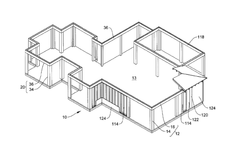
CA 3033775 2019-02-14
1
to withstand natural disasters; nevertheless, a wood framed house can be
fortified
with a number of metal braces, brackets and plates to increase its strength.
Yet, in
some cases these reinforced wood framed houses still do not stand up to high
level natural disasters. The building frame of a conventional wood stud homes
lacks the strength to resist the shear force exerted by high winds and/or
driving
rains which accompany hurricanes and tornadoes. By contrast, materials such as
concrete are very strong and have much greater resistance to shear forces. For
these reasons, pre-cast concrete panels; insulated concrete forms and site
casted
concrete walls are the strongest types of new home construction systems, but
they
are the costliest to build.
[0003] There is a need for a home building system which provides
strength and
resistance to storms that is comparable to conventional concrete building
systems,
at a more affordable cost.
[0004] There is a need for a home building system which can be erected
on
site without the need for specialized equipment to create a structurally sound
and
aesthetically pleasing home.
2
CA 3033775 2019-02-14
SUMMARY OF THE INVENTION
[0005] A permanent form member for a composite construction member has a
longitudinal axis and comprises an elongated body. The elongated body has a
first end, a second end, and an outer wall defining a concrete retaining
channel
therethrough, and a bracing member extending from the outer wall into the
concrete retaining channel. The bracing member is coterminous with the
elongated body. The bracing member is continuous. The bracing member and
the elongated body are unitary. The bracing member and the elongated body are
constructed from a material group consisting of polyvinylchloride,
acrylonitrile
butadiene styrene and polybutylene. The bracing member and the elongated body
are constructed by extrusion.
[0006] In one embodiment the permanent form member for a composite
construction member is a column form wherein the bracing member comprises a
least two ribs fixed to the outer wall at diametrically opposed positions
thereon.
The bracing member further comprises a tubular wall defining a central cavity
coaxial with the longitudinal axis of the permanent form member and disposed
within the concrete retaining channel; with a first end of each of the ribs
fixed to
the outer wall and a second end of each of the ribs being fixed to the tubular
wall,
thereby portioning the concrete retaining channel into longitudinally
extending sub-
channels.
3
CA 3033775 2019-02-14
1
[0007] In another embodiment the permanent form member for a composite
construction member is a beam form wherein the outer wall of the elongated
member is open along its entire length such that concrete retaining channel is
substantially U-shaped. The bracing member comprises at least three ribs fixed
to
the outer wall at diametrically opposed positions thereon and each of the ribs
defines a plurality of concrete filling portals.
[0008] A method of constructing a composite concrete house frame
comprises
the following steps. A permanent form member, being a column form comprising
an elongated body having a first end, and a second end, and an outer wall
defining
a concrete retaining channel therethrough; and a bracing member having at
least
two ribs fixed to the outer wall at diametrically opposed positions thereon,
is
placed on a foundation wall. The foundation wall has a plurality of portions
of
rebar having free ends extending therefrom. The column form is placed such
that
the first end of the elongated body is in contact with the foundation wall and
the
rebar extending from the foundation wall is received within the concrete
retaining
channel and extends beyond the second end of the elongated body. The column
form is framed in position with framing boards. The concrete retaining channel
is
filled with flowable high strength concrete and the concrete is allowed to set
forming a composite column. The foregoing steps are repeated iteratively to
form a
plurality of composite columns. The method of constructing a composite
concrete
house frame further comprises the step of inserting a plurality of portions of
rebar
into a concrete retaining channel defined in a permanent form member, being a
beam form. The beam form comprises an elongated body having a first end, and
4
CA 3033775 2019-02-14
a second end, and an outer wall defining the concrete retaining channel
therethrough and having a bracing member having at least three ribs fixed to
the
outer wall at diametrically opposed positions thereon. The beam form is then
placed on the top of the composite column and the rebar extending beyond the
column form is tied to the rebar positioned in the beam form. These steps are
repeated iteratively with a plurality of abutting beam forms. The next step is
tying
together the rebar positioned within the plurality of abutting beam forms. The
final
steps are filling the concrete retaining channels of the abutted beam forms
with
flowable, high strength concrete; and allowing the concrete to set, forming a
composite lintel supported on the plurality of composite columns.
BRIEF DESCRIPTION OF THE DRAWINGS
[0009] FIG.1 is a perspective view of the frame of a house constructed
in
accordance with the present invention.
[0010] FIG.2 is perspective view of column forms according to the
present
invention.
[0011] FIG.3 is a sectional view of the column forms view of column
forms
according to the present invention.
[0012] FIG.4 is top plan view of a beam form according to the present
invention.
[0013] FIG.5 is an enlarged end view of the beam form of FIG. 4.
CA 3033775 2019-02-14
[0014] FIG.6 is a perspective view of a partial column form in position
for
installation on a building slab.
[0015] FIG. 7 is a cross section of a simplified structure assembled
according
to the present invention.
[0016] FIG. 8 is a longitudinal section through one column of the
simplified
structure of FIG. 7.
[0017] FIG. 9 is an exploded perspective view of a partial wall
assembly of
framed column forms and beam forms.
[0018] FIG. 10 is a longitudinal sectional view of the rebar connection
of a
beam form and a column form mounted on a foundation wall with partially hidden
rebar connection shown in dotted outline.
[0019] FIG. 11 is a partial top plan view of a corner joint of two beam
forms with
partially hidden rebar connection shown in dotted outline.
DETAILED DESCRIPTION
[0020] Certain terminology is used in the following description for
convenience
only and is not limiting. The words "lower," "bottom," "upper," and "top"
designate
directions in the drawings to which reference is made. The words "inwardly,"
"outwardly," "upwardly" and "downwardly" refer to directions toward and away
from, respectively, the geometric center of the device, and designated parts
thereof, in accordance with the present disclosure. Unless specifically set
forth
herein, the terms "a," "an" and "the" are not limited to one element, but
instead
6
CA 3033775 2019-02-14
should be read as meaning "at least one." The terminology includes the words
noted above, derivatives thereof and words of similar import.
[0021] The frame of a house is primarily constructed of a plurality of
columns
supporting a plurality of beams which together form a frame or skeleton for
the
house. Various additional layers such as drywall, vapor barriers, siding,
stucco
etc. are then fixed to the skeleton to create an enclosed space having rooms,
doors, windows etc. FIG. 1 shows a schematic representation of a house frame
according to the present invention. The frame 10 is constructed of a plurality
of
composite construction members 12, of which there are two basic types:
composite columns 14 and composite beams 16. The composite construction
members 12 are intended to be assembled in place on site from the following
elements: a permanent form member 20, which surrounds and retains a portion of
concrete 19 that is strengthened with rebar 18. For clarification, it should
be noted
that the permanent form members 20 remain a component of the composite
construction members 12 in the finished frame 10 and the completed house.
[0022] The permanent form member 20 has a longitudinal axis, as
represented
by line A-A in FIG. 2. The permanent form member 20 comprises an elongated
body 22 having a first end 24, and a second end 26, and an outer wall 28
defining
a concrete retaining channel 30 therethrough. A bracing member 32 extends from
the outer wall 28 into the concrete retaining channel 30. The function of the
bracing member 32 is to provide increased strength and rigidity to the
permanent
form member 20, and to prevent the permanent form member 20 from bulging or
bursting when it is filled with concrete. There are two embodiments of the
7
CA 3033775 2019-02-14
1
permanent form member 20: a column form 34 shown in FIG 2 and 3; and a beam
form 36 which is shown in Fig 4 and Fig 5. General reference will be made to
the
permanent form member 20 for a composite construction member 12 when
discussing common features thereof. The term column form 34 will be used when
referring specifically to features required for construction of a composite
column
14. The term beam form 36 will be used when referring specifically to features
required for construction of a composite beam 16. The two embodiments of the
forming member 20 will now be discussed separately in greater detail.
[0023] The column form 34 is a component of a composite column 14. FIG.
2
shows a single column form 34 and additionally shows examples of the manner in
which multiple column forms may be assembled together to create more complex
structural columns for use at different positions in the house frame, as will
be
discussed in greater detail below. FIG. 3 shows cross sections of the column
form
34 in isolation and additionally shows examples of column forms assembled
together to create more the complex structural column profiles which
correspond
to those shown in FIG. 2. The cross section of the single column form 34 in
isolation (identified by arrow 50) is enlarged to show detail of its
structure.
[0024] As mentioned above, the function of the bracing member 32 is to
provide increased strength and rigidity and to prevent the form member from
bulging or bursting when filled with concrete. Essentially the bracing member
32
maintains an inwardly directed force urging the diametrically opposed
positions on
the outer wall toward one another to counteract the outward force exerted by
concrete which is poured into the column form. In the column form 34, the
outer
8 .
1
CA 3033775 2019-02-14
1
wall 28 defines a perimeter having four sides. At least two ribs 42 and 44 are
each
fixed to diametrically opposed positions on two facing sides.
[0025] At its simplest, the bracing member 32 comprises at least two
ribs 42,
44 fixed to the outer wall 28 at diametrically opposed positions on the outer
wall
28. An example of a simple bracing member 32 is shown in the column form
identified by arrow 40 and FIG. 3. The bracing member 32 comprises a rib 42
fixed to the outer wall 28 at diametrically opposed positions. A rib 44 is
fixed to the
outer wall 28 at positions at diametrically opposed positions. A bracing means
having only a single rib attached to only a single pair of diametrically
opposed
points on the outer wall would permit deformation of the outer wall in at
least one
direction in response to outward pressure exerted by concrete and would likely
fail.
[0026] In FIG. 3, general reference arrow 50 identifies the variant of
column 34
which illustrates the preferred bracing member 32. Bracing member 32 further
comprises a tubular wall 52 defining a central cavity 54 coaxial with the
longitudinal axis of elongated body 22of the column form 34 and disposed with
in
the concrete retaining channel 30. The central cavity 54 can be used to
accommodate 5/8 inch to 1 inch diameter steel reinforcing bar to reinforce the
concrete. Alternatively, conventional rebar can be used, as will be discussed
in
greater detail below.
[0027] In this embodiment, a first end of each of the ribs is fixed to
the outer
wall and a second end of each of the ribs is fixed to the tubular wall 52.
More
specifically, first end 56 of rib 42 is fixed to the outer wall at position
46A and
second end 58 of rib 42 is fixed to the tubular wall 52. The first end 60 of
rib 44 is
9
CA 3033775 2019-02-14
I
fixed to the outer wall 28 at position 48A, and second end 62 of rib 44 is
fixed to
the tubular wall 52. A third rib 64 and a fourth rib 66 are likewise fixed to
the
tubular wall 52 and to the outer wall 28 at points 46B and 48B. Thus, the
concrete
retaining channel 30 is portioned into longitudinally extending sub-channels
30A,
30B, 300, and 30D. This preferred embodiment provides increased strength due
to the presence of the tubular wall 52. The tubular wall 52 disperses the
forces
along its perimeter to more uniformly resist the outward force exerted by the
concrete.
[0028] The bracing member 32 is coterminous with the elongated body 22
of
the column form 34. It is preferable, that the bracing member 32 be continuous
in
order to provide uniform resistance to the toward force exerted by the
concrete.
Less preferred embodiments in which column form 24 has bracing members 32
disposed at a plurality of positions along on the elongated body 22 may be
possible. Such embodiments would be more expensive to manufacture and
functionally less effective.
[0029] It is preferred that the bracing member 32 and the elongated body
22 of
the column form 34 are unitary. When the elongated body and the bracing
member are a unitary body, then the column form 34 can be constructed by an
extrusion process. Manufacturing by extrusion can produce many column forms in
a short period of time and at low cost (once extrusion molds have been
created).
The column form 34 is constructed from a material selected from the group
consisting of polyvinylchloride (PVC), acrylonitrile butadiene styrene (ABS)
and
polybutylene. It is preferred to construct the column form 34 as a PVC
extrusion.
1
CA 3033775 2019-02-14
[0030] Referring now to FIG. 4 and FIG. 5, the second embodiment of the
permanent form member 20 is a beam form 36. The beam form 36 has a
longitudinal axis identified by line B in FIG. 4. The beam form 36 comprises
an
elongated body 70 having a first end 72 and a second end 74. The elongated
body 70 has an outer wall 76 defining a concrete retaining channel 78. It
should
be noted that the elongated body 70 of the beam form 36 is open along its
entire
length such that the concrete retaining channel 78 is substantially U-shaped.
The
beam form 36 further comprises a bracing member 80 extending from the outer
wall 76 into the concrete retaining channel 78. The bracing member 80
comprises
at least three ribs 82, 84, 85 which are fixed to the outer wall 76 at
diametrically
opposed positions thereon. The first rib 82 is fixed to the outer wall 76 at
diametrically opposed positions 86A and 86B. The second rib 84 is fixed to the
outer wall 76 at diametrically opposed positions 88A and 88B. The third rib 85
is
fixed to the outer wall 76 at diametrically opposed positions 89A and89B. The
ribs
82, 84, and 85 each being fixed to the outer wall 76 at diametrically opposed
positions thereon urge the diametrically opposed positions on the outer wall
toward one another to counteract the outward force exerted by concrete which
is
poured into the beam form 36.
[0031] In a manner analogous to the column form, the bracing member 80
of
the beam form 36 is coterminous with the elongated body 70. It is likewise
preferable for the bracing member 70 to be continuous in order to provide
uniform
resistance to the outward force exerted by the concrete. It is preferred that
the
bracing member 80 and the elongated body 70 of the beam form 36 are unitary.
11
CA 3033775 2019-02-14
1
When the elongated body 70 and the bracing member 80 are a unitary body, then
the beam form 36 can be constructed by an extrusion process from a material
selected from the group consisting of polyvinylchloride (PVC), acrylonitrile
butadiene styrene (ABS) and polybutylene. Again, the preferred material is
PVC.
[0032] Each of the at least three ribs 82, 84, 85 of the bracing members
80
defines a plurality of concrete filling portals 90. The concrete filling
portals 90 are
preferably 3 5/8 inches wide by 8 inches long and are spaced approximately 8
inches apart. The concrete filling portals are present in all of the ribs 82,
84, and
85 and are preferably aligned in a stack one above the other. This positioning
allows concrete 19 to freely flow downward to evenly and completely fill the
concrete retaining channel 78. Moreover, it is preferred that the beam forms
36 be
constructed as extrusions of PVC. The stacked alignment of the concrete
filling
portals 90 can readily be formed by punching once a length of PVC material has
been extruded having the contours of the beam form. As will be discussed in
greater detail below, concrete is poured into the U-shaped concrete retaining
channel 78 through the concrete filling portals 90. Although the concrete
retaining
channel 78 appears to be divided into segments by the ribs 82, 84 and 85 of
the
bracing means, the presence of the plurality of concrete filling portals
permits the
fluid communication and filing of concrete retaining channel 78 as a single
channel. A rebar rest 92 is located on each of the at least three ribs 82, 84
85.
The rebar rests 92 may take the form of a pair of projections spaced apart
from
one another to allow a beam rebar 94 to rest therebetween. Alternatively, as
shown in FIG 4 and FIG 5, the rebar rest is in the form of a groove 92 which
runs
12
1
CA 3033775 2019-02-14
longitudinally along the length of the each of the ribs 82, 84. Typically
there will be
more than one rebar rest to facilitate multiple lengths of rebar within the
composite
beam 16. In the preferred embodiment of the present invention shown in FIG. 5,
the ribs 82 and 84 each have two rebar rests 92, to accommodate two portions
of
beam rebar 94 on each rib 82, 84. Rib 85 is positioned nearest the bottom of
the
U-shaped concrete retaining channel 78, and will be subjected to the greatest
downward force when the beam form 36 is filled with concrete to form the
composite beam 16. Rib 85 of beam form 36 is provided with three or more rebar
rests 92, to accommodate three or more portions of beam rebar 94 to resist
buckling when the composite beam 16 is under load.
[0033] In use, the permanent form members 20 of the present invention
are
anchored to a concrete building slab 13 and/or foundation wall 108, as the
case
may be, and connected together and fused with reinforced concrete to create a
composite construction member 12. A plurality of composite constructions
members together defines the perimeter of the house and interior load bearing
walls. The purpose of the concrete frame 10 is to increase the structural
strength
of a conventional wood stud home without compromising the aesthetic look of
the
dwelling. A concrete frame as the structural strength to resist the shear
force
exerted by high winds and/or driving rains which accompany hurricanes and
tornadoes.
[0034] FIG. 1 illustrates a composite concrete frame 10 for a house. The
frame
is defined by a plurality of composite construction members 12 anchored to the
concrete building slab 13 (foundation walls not shown in FIG. 1) and connected
to
13
CA 3033775 2019-02-14
one another to permanent form a continuous composite concrete perimeter. Two
types of composite construction members 12, are used: the composite columns
14 and the composite beams 16. The composite columns 14 are anchored to the
building slab. The composite beams 16 are connected to the composite columns
14 and to each other. Composite columns 14 having different cross-sectional
profiles are used for different portions of the composite frame 10.
[0035] It is advantageous, though not necessary to manufacture the
column
forms 34 to a standard size widely used in the building industry: 5 1/2 inches
by 51/2
inches in width and 8 feet in length. The outer wall 28 of the column form 34
is
approximately 1/8 inch thick. The column form 34 of the present invention
serves
as a modular building block from which to form composite columns 14 of the
desired shape for a particular application. FIG 2 and FIG 3 show the various
arrangements of column forms 34 for us in constructing composite columns of
various shapes. FIG. 7 shows a cross section of a simplified composite frame
10
in greater detail and illustrates situations in which more complex
arrangements of
column forms 34 would be used. Where composite columns 14 of modest strength
are needed, such as to support an interior wall 100, a single column form 34
will
be used. More robust rectangular columns 102, such as those which support the
running length of an exterior wall are formed by placing two column forms 34
side
by side. L-shaped columns 104, formed by assembling together three column
forms 34, are used to define corners in the perimeter of the frame 10. T-
shaped
columns 106 (also formed by assembling together three column forms 34) are
used to define the meeting of an interior wall 100 with the perimeter of the
frame
14
CA 3033775 2019-02-14
10. Although not shown in FIG. 7, cross shaped columns (formed by assembling
together four column forms 34) can be used at the 90-degree junction of two
running walls. Additionally, more robust square columns can be formed by
assembling four column forms together.
[0036] Details of the construction method will now be discussed. FIG. 8
and
FIG. 10 illustrate the manner in which composite columns 14 are anchored to a
foundation wall 108. Footing rebar (not shown) is tied with binding wire or
rebar
ties (not shown) to the foundation wall rebar 110 in the conventional manner.
Rebar 18 for the composite columns 34 is set in place in position in the
foundation
wall 108 (and/or the concrete building slab as the case may be) and tied to
the
foundation wall (or slab) rebar. The foundation wall and concrete slab are
cast in
place. The rebar 18 for the composite columns 14 protrudes from the foundation
wall 108. Multiple portions of rebar 18 may be tied together in the
conventional
manner to achieve the desired length. A column form 34 is positioned such that
the first end 24 of the elongated body 22 is in contact with the foundation
wall 108
and the rebar 18 is received with in the concrete retaining channel 30. More
specifically, portions of rebar 18 are received within the selected ones of
the sub-
channels 30A, 30B, 30C, and 30D and extend throughout the length of the column
forms 34 and protrudes above the column forms 34. Alternatively, if steel
reinforcements of a greater diameter than conventional rebar are being used,
they
can be accommodated in the central cavity 54. As can be seen in FIG. 6 and FIG
7, it is preferred that two portions of rebar 18 are received and positioned
in two
selected sub-channels oriented diagonally across from one another. The column
CA 3033775 2019-02-14
1
forms 34 are self-supporting on the foundation wall and held in position by
the
rebar 18. The column forms 34 are then framed into place using conventional
2x6
framing boards 114. For clarity, it should be noted that when multiple column
forms 34 are used to assemble complex column shapes (e.g. L-shape, T-shape)
the individual column forms 34 are not affixed to one another directly.
Instead they
are held in position abutting one another by the 2x6 framing boards 114. Once
all
column forms 34 have been positioned and framed into place, flowable, high
strength concrete is then poured into the concrete retaining channel 30
including
the central cavity 54 at the second end of the elongated body 22. The concrete
will flow down into the column form 34 under gravity filling the central
cavity 54 and
the concrete retaining channel 30 (including sub-channels 30A, 30B, 300, and
30D) and surrounding the rebar 18. The bracing members 32 enable the column
forms 34 to retain their cross-sectional shape against the outward force
exerted by
the concrete on the outer wall 28 of the elongated body 22. The concrete is
then
allowed to set in the column forms 34 to create the composite columns 14.
[0037] The formation and installation of composite beams 16 begins by
inserting portions of beam rebar 94 into the concrete retaining channel 78 of
the
beam form 36. The beam rebar 94 will rest on the rebar rests 92 located on the
first rib 82, the second rib 84, and the third rib 85 which are fixed to the
outer wall
76 at diametrically opposed positions 86A-86B, 88A-88B and 89A-89B
respectively. The beam forms 36 are then lifted into place resting on the
composite
columns 14 and the framing boards 114 of the wood/metal stud wall frame. The
rebar 18 protruding from the composite columns 14 is then tied to the rebar 94
16
CA 3033775 2019-02-14
contained in the beam forms 36 using conventional rebar ties or wire.
Alternatively, an additional short piece of rebar 95 can be bent to a 90-
degree
angle and placed alongside rebar in the beam forms 36 at corner positions
along
the frame and tied to the rebar of adjacent beam forms to create a stronger
corner
structure. The insertion and tying of an additional piece of rebar is a known
technique in the forming industry.
[0038] The beam forms 36 are preferably 5 1/2 inches wide by 11 inches
high
by 1/8" thick and 11 feet long. This is a standard size for construction beams
such
that construction workers would be familiar with beams of these dimensions.
Other beam form dimensions could be contemplated within the scope of the
invention. Each of the beam forms 36 is connected end-to-end with the next
adjacent beam form 36 thus creating a single continuous form connecting all
exterior walls and load bearing interior walls of the building. If desired,
the points of
abutment of adjacent beams can be taped with construction tape to prevent
concrete leaking from small gaps. Flowable, high strength concrete 19 is then
poured down into the open end of the U-shaped concrete retaining channel 78
through each of the beam forms 36. The concrete 19 will flow downward under
gravity, through the concrete filling portals 90 in each of the first rib 82,
the second
rib 84, and the third rib 85, eventually filling the entire concrete retaining
channel
78 and surrounding the portions of rebar 94. The concrete 19 flows from the
retaining channel 78 to retaining 78 inside adjacent beam forms 36,36 filling
all
available space. The concrete is then allowed to set creating a single
continuous
concrete lintel 118 (as can be seen in FIG. 1) connecting all exterior walls
and load
17
CA 3033775 2019-02-14
bearing interior walls of the building, through the interconnection of the all
of the
composite beams 16 and the composite columns 14.
[0039] The concrete structure will be completed and enclosed with typical
construction materials, such as plywood, water/moisture barrier 120, drywall
122,
siding 124, etc. concealing the concrete house frame 10. Conventional roofing
assemblies can then install on the house frame 10. Anchor bolts can be
embedded in concrete 19 of lintel 118 and wall plates are placed over anchor
bolts
and secured with washers and nuts. Hurricane straps can be installed to fasten
the roof rafters to the frame.
[0040] The corresponding structures, materials, acts, and equivalents of all
means
or step plus function elements in the claims below are intended to include any
structure, material, or act for performing the function in combination with
other
claimed elements as specifically claimed. The description of the present
invention
has been presented for purposes of illustration and description, but is not
intended
to be exhaustive or limited to the invention in the form disclosed. Many
modifications and variations will be apparent to those of ordinary skill in
the art
without departing from the scope and spirit of the invention. The embodiment
was
chosen and described in order to best explain the principles of the invention
and
the practical application, and to enable others of ordinary skill in the art
to
understand the invention for various embodiments with various modifications as
are suited to the particular use contemplated.
18
CA 3033775 2019-02-14