Note: Descriptions are shown in the official language in which they were submitted.
CA 03034025 2019-02-14
WO 2018/063854 PCT/US2017/052205
1
ENHANCEMENTS TO PHASE-NOISE COMPENSATION REFERENCE SIGNAL
DESIGN AND SCRAMBLING
CROSS REFERENCES
[0001] The present Application for Patent claims priority to U.S. Patent
Application No.
15/707,821 by Akkarakaran et al., entitled "Enhancements To Phase-Noise
Compensation
Reference Signal Design And Scrambling," filed September 18, 2017; and to U.S.
Provisional Patent Application No. 62/401,049 by Akkarakaran et al., entitled
"Enhancements To Phase-Noise Compensation Reference Signal Design and
Scrambling,"
filed September 28, 2016; each of which is assigned to the assignee hereof.
INTRODUCTION
[0002] The following relates generally to wireless communication, and more
specifically
to enhancements to phase-noise compensation reference signal design and
scrambling.
[0003] Wireless communications systems are widely deployed to provide
various types of
communication content such as voice, video, packet data, messaging, broadcast,
and so on.
These systems may be capable of supporting communication with multiple users
by sharing
the available system resources (e.g., time, frequency, and power). Examples of
such multiple-
access systems include fourth generation (4G) systems such as a Long Term
Evolution (LTE)
systems or LTE-Advanced (LTE-A) systems, and fifth generation (5G) systems
which may
be referred to as New Radio (NR) systems. These systems may employ
technologies such as
code division multiple access (CDMA), time division multiple access (TDMA),
frequency
division multiple access (FDMA), orthogonal frequency division multiple access
(OFDMA),
or discrete Fourier transform-spread-orthogonal frequency division
multiplexing (DFT-s-
OFDM). A wireless multiple-access communications system may include a number
of base
stations or network access nodes, each simultaneously supporting communication
for
multiple communication devices, which may be otherwise known as user equipment
(UE).
[0004] In some cases, transmissions in a wireless communications system may
be
impacted by interference. As a result, a receiver, such as a UE, may use
reference signals to
mitigate interference. Depending on a location of the reference signals within
wireless
resources, however, a receiver may be unable to efficiently receive the
reference signals due
to interference with tones within the resources. Some receivers may be able to
use reference
CA 03034025 2019-02-14
WO 2018/063854 PCT/US2017/052205
2
signals assigned to other receivers. However, transmitting additional
information to enable
this reference signal sharing may significantly increase scheduling overhead
and create
additional problems. Thus, communication efficiency within the wireless
communications
system may benefit from techniques that enable coherent scheduling of
reference signals and
improve flexibility for reference signal reception at a receiver.
SUMMARY
[0005] A method of wireless communication is described. The method may
include
identifying a frequency corresponding to a direct current (DC) tone within a
set of resource
blocks, determining a frequency for each of one or more phase-noise tracking
reference
signals (PTRS) based at least in part on the DC tone, each determined
frequency different
from the frequency corresponding to the DC tone, and transmitting the one or
more PTRS
using the set of resource blocks based at least in part on the determined
frequency.
[0006] An apparatus for wireless communication is described. The apparatus
may include
means for identifying a frequency corresponding to a DC tone within a set of
resource blocks,
means for determining a frequency for each of one or more PTRS based at least
in part on the
DC tone, each determined frequency different from the frequency corresponding
to the DC
tone, and means for transmitting the one or more PTRS using the set of
resource blocks based
at least in part on the determined frequency.
[0007] Another apparatus for wireless communication is described. The
apparatus may
include a processor, memory in electronic communication with the processor,
and
instructions stored in the memory. The instructions may be operable to cause
the processor to
identify a frequency corresponding to a DC tone within a set of resource
blocks, determine a
frequency for each of one or more PTRS based at least in part on the DC tone,
each
determined frequency different from the frequency corresponding to the DC
tone, and
transmit the one or more PTRS using the set of resource blocks based at least
in part on the
determined frequency.
[0008] A non-transitory computer readable medium for wireless communication
is
described. The non-transitory computer-readable medium may include
instructions operable
to cause a processor to identify a frequency corresponding to a DC tone within
a set of
resource blocks, determine a frequency for each of one or more PTRS based at
least in part
on the DC tone, each determined frequency different from the frequency
corresponding to the
CA 03034025 2019-02-14
WO 2018/063854 PCT/US2017/052205
3
DC tone, and transmit the one or more PTRS using the set of resource blocks
based at least in
part on the determined frequency.
[0009] Some examples of the method, apparatus, and non-transitory computer-
readable
medium described above may further include processes, features, means, or
instructions for
transmitting an indication of the identified frequency corresponding to the DC
tone.
[0010] Some examples of the method, apparatus, and non-transitory computer-
readable
medium described above may further include processes, features, means, or
instructions for
identifying that a resource block of the set of resource blocks overlaps with
the DC tone,
wherein the one or more PTRS may be transmitted using one or more resource
blocks of the
set of resource blocks that may be different from the resource block including
the DC tone.
[0011] Some examples of the method, apparatus, and non-transitory computer-
readable
medium described above may further include processes, features, means, or
instructions for
identifying that each resource block of the set of resource blocks includes at
least some of the
one or more PTRS, wherein the determining may be based at least in part on
identifying that
each resource block includes at least some of the one or more PTRS.
[0012] Some examples of the method, apparatus, and non-transitory computer-
readable
medium described above may further include processes, features, means, or
instructions for
identifying that a first resource block of the set of resource blocks overlaps
with the DC tone,
wherein the determining comprises assigning at least some of the one or more
PTRS to one or
more frequencies of the first resource block.
[0013] In some examples of the method, apparatus, and non-transitory
computer-readable
medium described above, the frequency corresponding to each of the one or more
PTRS may
be based at least in part on a number of component carriers, a system
bandwidth, or both.
[0014] In some examples of the method, apparatus, and non-transitory
computer-readable
medium described above, a frequency density of the PTRS may be based at least
in part on a
number of resource blocks in the set of resource blocks.
[0015] Some examples of the method, apparatus, and non-transitory computer-
readable
medium described above may further include processes, features, means, or
instructions for
identifying a plurality of tones across the set of resource blocks different
from the frequency
corresponding to the DC tone, the plurality of tones corresponding to a
plurality of symbols
across the set of resource blocks and associated with at least one antenna
port. Some
CA 03034025 2019-02-14
WO 2018/063854 PCT/US2017/052205
4
examples of the method, apparatus, and non-transitory computer-readable medium
described
above may further include processes, features, means, or instructions for
assigning a first
subset of the plurality of tones for data. Some examples of the method,
apparatus, and non-
transitory computer-readable medium described above may further include
processes,
features, means, or instructions for assigning a second subset of the
plurality of tones for
PTRS. Some examples of the method, apparatus, and non-transitory computer-
readable
medium described above may further include processes, features, means, or
instructions for
scrambling a modulation symbol for each tone of the second subset. Some
examples of the
method, apparatus, and non-transitory computer-readable medium described above
may
further include processes, features, means, or instructions for transmitting
the first subset and
the second subset using the scrambled modulation symbols.
[0016] In some examples of the method, apparatus, and non-transitory
computer-readable
medium described above, the transmitting comprises transmitting the second
subset using the
at least one antenna port based at least in part on a resource block
assignment, the resource
block assignment comprising a number of layers used for data in the set of
resource blocks.
[0017] In some examples of the method, apparatus, and non-transitory
computer-readable
medium described above, the second subset corresponds to an antenna port of
the at least one
antenna port. Some examples of the method, apparatus, and non-transitory
computer-readable
medium described above may further include processes, features, means, or
instructions for
refraining from transmitting PTRS using the antenna port. Some examples of the
method,
apparatus, and non-transitory computer-readable medium described above may
further
include processes, features, means, or instructions for reassigning the second
subset for data
or a vacant tone.
[0018] In some examples of the method, apparatus, and non-transitory
computer-readable
medium described above, the second subset corresponds to an antenna port of
the at least one
antenna port and contains at most one tone per resource block of the set of
resource blocks.
Some examples of the method, apparatus, and non-transitory computer-readable
medium
described above may further include processes, features, means, or
instructions for assigning
a third subset of the plurality of tones for a demodulation reference signal
(DMRS), the third
subset and the first subset overlapping partially, overlapping completely, or
being disjoint,
and the third subset corresponding to a group of antenna ports of the at least
one antenna port.
Some examples of the method, apparatus, and non-transitory computer-readable
medium
CA 03034025 2019-02-14
WO 2018/063854 PCT/US2017/052205
described above may further include processes, features, means, or
instructions for
transmitting the third subset using the group of antenna ports, wherein the
third subset
comprises each of the at most one tone per resource block of the set of
resource blocks.
[0019] A method of wireless communication is described. The method may
include
generating a DFT-s-OFDM symbol, appending a PTRS to the generated DFT-s-OFDM
symbol, appending a cyclic prefix to the generated DFT-s-OFDM symbol, and
transmitting
the generated DFT-s-OFDM symbol comprising the cyclic prefix and the PTRS.
[0020] An apparatus for wireless communication is described. The apparatus
may include
means for generating a DFT-s-OFDM symbol, means for appending a PTRS to the
generated
DFT-s-OFDM symbol, means for appending a cyclic prefix to the generated DFT-s-
OFDM
symbol, and means for transmitting the generated DFT-s-OFDM symbol comprising
the
cyclic prefix and the PTRS.
[0021] Another apparatus for wireless communication is described. The
apparatus may
include a processor, memory in electronic communication with the processor,
and
instructions stored in the memory. The instructions may be operable to cause
the processor to
generate a DFT-s-OFDM symbol, append a PTRS to the generated DFT-s-OFDM
symbol,
append a cyclic prefix to the generated DFT-s-OFDM symbol, and transmit the
generated
DFT-s-OFDM symbol comprising the cyclic prefix and the PTRS.
[0022] A non-transitory computer readable medium for wireless communication
is
described. The non-transitory computer-readable medium may include
instructions operable
to cause a processor to generate a DFT-s-OFDM symbol, append a PTRS to the
generated
DFT-s-OFDM symbol, append a cyclic prefix to the generated DFT-s-OFDM symbol,
and
transmit the generated DFT-s-OFDM symbol comprising the cyclic prefix and the
PTRS.
[0023] In some examples of the method, apparatus, and non-transitory
computer-readable
medium described above, the cyclic prefix may be appended to the beginning of
the
generated DFT-s-OFDM symbol and the PTRS may be appended to a beginning of the
cyclic
prefix, to an end of the generated DFT-s-OFDM symbol, or a combination
thereof.
[0024] In some examples of the method, apparatus, and non-transitory
computer-readable
medium described above, the generated DFT-s-OFDM symbol comprises a guard
interval,
and wherein the appending the PTRS to the generated DFT-s-OFDM symbol
comprises
replacing at least a portion of the guard interval with the PTRS.
CA 03034025 2019-02-14
WO 2018/063854 PCT/US2017/052205
6
[0025] Some examples of the method, apparatus, and non-transitory computer-
readable
medium described above may further include processes, features, means, or
instructions for
performing a weighted-overlap-and-add scheme within the generated DFT-s-OFDM
symbol
at a boundary between the generated DFT-s-OFDM symbol and the appended PTRS.
[0026] In some examples of the method, apparatus, and non-transitory
computer-readable
medium described above, appending the PTRS to the generated DFT-s-OFDM symbol
comprises assigning the PTRS to an input of a discrete Fourier transform (DFT)
spreading
operation used to generate the DFT-s-OFDM symbol. In some examples of the
method,
apparatus, and non-transitory computer-readable medium described above,
appending the
PTRS to the generated DFT-s-OFDM symbol comprises appending the PTRS to an
output of
an inverse fast Fourier transform (IFFT) operation used to generate the DFT-s-
OFDM
symbol.
[0027] Some examples of the method, apparatus, and non-transitory computer-
readable
medium described above may further include processes, features, means, or
instructions for
initializing the scrambling on a per-subframe basis or a per-symbol basis. In
some examples
of the method, apparatus, and non-transitory computer-readable medium
described above, the
initializing may be based at least in part on a function of a cell identifier,
a subframe index, a
symbol index, or a combination thereof. Some examples of the method,
apparatus, and non-
transitory computer-readable medium described above may further include
processes,
features, means, or instructions for assigning scrambled modulation symbols to
the second
subset based at least in part on an ordering of a port-index, a tone index, a
symbol index, or a
combination thereof.
[0028] Some examples of the method, apparatus, and non-transitory computer-
readable
medium described above may further include processes, features, means, or
instructions for
determining that a tone of the second subset may be unused for PTRS. Some
examples of the
method, apparatus, and non-transitory computer-readable medium described above
may
further include processes, features, means, or instructions for discarding the
modulation
symbol corresponding to the tone based at least in part on the determining. In
some examples
of the method, apparatus, and non-transitory computer-readable medium
described above, the
first subset or the second subset comprise vacant tones.
[0029] Some examples of the method, apparatus, and non-transitory computer-
readable
medium described above may further include processes, features, means, or
instructions for
CA 03034025 2019-02-14
WO 2018/063854 PCT/US2017/052205
7
determining a first scrambling sequence for a first receiver and a second
scrambling sequence
for a second receiver. Some examples of the method, apparatus, and non-
transitory computer-
readable medium described above may further include processes, features,
means, or
instructions for assigning the first scrambling sequence or the second
scrambling sequence to
one or more tones of the second subset based at least in part on transmissions
intended for the
first receiver or the second receiver.
[0030] Some examples of the method, apparatus, and non-transitory computer-
readable
medium described above may further include processes, features, means, or
instructions for
initializing the scrambling based at least in part on receiver-specific
information, the receiver-
specific information comprising at least a radio network temporary identifier
(RNTI). Some
examples of the method, apparatus, and non-transitory computer-readable medium
described
above may further include processes, features, means, or instructions for
mapping the
modulation symbol onto at least one tone of the second subset.
BRIEF DESCRIPTION OF THE DRAWINGS
[0031] FIG. 1 illustrates an example a wireless communications system that
supports
enhancements to PTRS design and scrambling in accordance with one or more
aspects of the
present disclosure;
[0032] FIG. 2 illustrates an example of a wireless communications system
that supports
enhancements to PTRS design and scrambling in accordance with one or more
aspects of the
present disclosure;
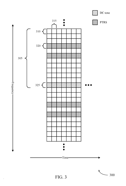
[0033] FIG. 3 illustrates an example of wireless resources in a system that
supports
enhancements to PTRS design and scrambling in accordance with one or more
aspects of the
present disclosure;
[0034] FIGs. 4A through 4D illustrate examples of DFT-s-OFDM symbol
configurations
in a system that supports enhancements to PTRS design and scrambling in
accordance with
one or more aspects of the present disclosure;
[0035] FIG. 5 illustrates an example of another DFT-s-OFDM symbol
configuration in a
system that supports enhancements to PTRS design and scrambling in accordance
with one or
more aspects of the present disclosure;
CA 03034025 2019-02-14
WO 2018/063854 PCT/US2017/052205
8
[0036] FIGs. 6 through 9 illustrate examples of process flows in a system
that supports
enhancements to PTRS design and scrambling in accordance with one or more
aspects of the
present disclosure;
[0037] FIGs. 10 through 12 show block diagrams of a device that supports
enhancements
to PTRS design and scrambling in accordance with one or more aspects of the
present
disclosure;
[0038] FIG. 13 illustrates a block diagram of a system including a base
station that
supports enhancements to PTRS design and scrambling in accordance with one or
more
aspects of the present disclosure; and
[0039] FIGs. 14 and 15 illustrate methods for enhancements to PTRS design
and
scrambling in accordance with one or more aspects of the present disclosure.
DETAILED DESCRIPTION
[0040] The described techniques relate to improved methods, systems,
devices, and
apparatuses that support enhancements to phase-noise compensation reference
signals
(PCRS) design and scrambling. Generally, the described techniques provide for
identification
of a DC tone, which may influence transmissions of PCRS (e.g., which may
alternatively be
referred to as phase-noise tracking reference signals, phase tracking
reference signals, or
PTRS). It is to be understood that, though described in the context or PTRS
collision
avoidance, the DC tone indication may be used for other purposes (e.g., multi-
user
scheduling) without deviating from the scope of the present disclosure.
[0041] As an example, transmitting PTRS to avoid collisions with the DC
tone may
enable improved reception of PTRS by a base station or a UE. In one example,
multiple
PTRS may be transmitted using sets of resource blocks (RBs), where a frequency
for each
PTRS within the sets of RBs is different from a frequency corresponding to a
DC tone. In
another example, time-domain-based PTRS may be used, where a DFT-s-OFDM symbol
may include a cyclic prefix and a PTRS appended to a beginning or end of the
DFT-s-OFDM
symbol. In aspects, a DFT-s-OFDM symbol may alternatively be referred to as a
single-
carrier frequency division multiplexing (SC-FDM) symbol. Additionally or
alternatively, a
guard-interval-based DFT-s-OFDM symbol may include a PTRS that replaces part
or all of a
guard interval. The PTRS may be inserted either before or after the DFT-
spreading operation.
In some examples, subsets of tones used for PTRS across a system bandwidth may
be
CA 03034025 2019-02-14
WO 2018/063854 PCT/US2017/052205
9
transmitted using a scrambled modulation symbol, where at least one antenna
port may be
used for the transmission of PTRS.
[0042] In some wireless communications systems, phase noise may impact
communications performance. Phase noise levels may increase with higher
carrier
frequencies, and wireless communications systems that use, for example,
carrier frequencies
above 6 GHz, may thus be affected by increasing phase noise. Accordingly, a
reference
signal, such as a PTRS, may be transmitted by a UE and used by a receiver
(e.g., a base
station) to estimate and correct the phase noise.
[0043] Wireless communications systems, such as orthogonal frequency
division
multiplexing (OFDM) systems, may include transmissions of unmodulated tones or
subcarriers that are used by receiving devices to identify a center frequency
of transmitted
wireless resources (e.g., a DC tone). In aspects of the present disclosure, a
UE may identify a
DC tone for an uplink transmission and convey an indication of the DC tone to
a target base
station. For example, the UE may convey the DC tone location using semi-static
signaling
(e.g., RRC signaling or semi-static uplink control signaling). In some cases,
the UE may
avoid collisions with the DC tone (e.g., for DMRS and/or PTRS transmissions).
For example,
PTRS transmissions may collide with the DC tone, preventing receivers from
efficiently
utilizing the PTRS for phase noise correction. That is, if a frequency for a
PTRS (e.g., or a
DMRS) is close to, or overlaps with, a frequency corresponding to a DC tone,
then PTRS
reception on those frequencies may be compromised by a DC offset within the
receiver.
[0044] In some cases, PTRS transmissions may be scheduled on frequencies
different
from a frequency or frequencies that corresponds to a DC tone. That is, PTRS
may be
transmitted within wireless resources (e.g., RBs) using a design that avoids
transmitting the
PTRS on a same frequency that corresponds to a DC tone. As a result,
frequencies used for
PTRS transmissions to a receiver may be based on the DC tone, and may avoid
interference
caused by PTRS frequencies overlapping with the DC tone.
[0045] In some examples, scrambling of PTRS tones may be performed
according to
different schemes, such as a receiver-independent scheme and/or a receiver-
specific scheme.
In a receiver-independent scheme, even though PTRS transmissions may be
directed at a
specific receiver to help that receiver correct phase noise, a receiver may
also use any PTRS
that is scheduled or intended for other receivers. Accordingly, a scrambler
may generate a
scrambling modulation symbol for every possible PTRS tone across a system
bandwidth,
CA 03034025 2019-02-14
WO 2018/063854 PCT/US2017/052205
enabling receivers to use PTRS that may be scheduled for different receivers.
Additionally or
alternatively, a receiver may not gain much from using PTRS sent to other
receivers, and
control information may be to tailored for a PTRS scrambling to be specific to
a particular
receiver and the receiver's assignment type.
[0046] Additionally, a waveform for DFT-s-OFDM may be configured to include
a time-
domain PTRS. For example, a DFT-s-OFDM symbol may be generated and a cyclic
prefix
may be appended, followed by a time domain PTRS inserted after the addition of
the cyclic
prefix, at a start, an end, or both of the DFT-s-OFDM symbol. That is, pre-DFT
or post-DFT
insertion of PTRS for an uplink DFT-s-OFDM symbol may be supported in
accordance with
techniques described below.
[0047] Aspects of the disclosure are initially described in the context of
a wireless
communications system. Further examples are then provided that illustrate
frequencies used
for PTRS in addition to time-domain PTRS transmissions. Aspects of the
disclosure are
further illustrated by and described with reference to apparatus diagrams,
system diagrams,
and flowcharts that relate to enhancements to PTRS design and scrambling.
[0048] FIG. 1 illustrates an example of a wireless communications system
100 in
accordance with one or more aspects of the present disclosure. The wireless
communications
system 100 includes base stations 105 (e.g., gNodeBs (gNBs), and/or radio
heads (RHs)),
UEs 115, and a core network 130. In some examples, the wireless communications
system
100 may be a LTE network, a LTE-A network, or a NR network. In some cases,
wireless
communications system 100 may support enhanced broadband communications, ultra-
reliable (e.g., mission critical) communications, low latency communications,
or
communications with low-cost and low-complexity devices.
[0049] Base stations 105 may wirelessly communicate with UEs 115 via one or
more
base station antennas. Base stations 105 described herein may include or may
be referred to
by those skilled in the art as a base transceiver station, a radio base
station, an access point, a
radio transceiver, a NodeB, an eNodeB (eNB), a next-generation Node B or giga-
nodeB
(either of which may be referred to as a gNB), a Home NodeB, a Home eNodeB, or
some
other suitable terminology. Wireless communications system 100 may include
base stations
105 of different types (e.g., macro or small cell base stations). The UEs 115
described herein
may be able to communicate with various types of base stations 105 and network
equipment
including macro eNBs, small cell eNBs, gNBs, relay base stations, and the
like.
CA 03034025 2019-02-14
WO 2018/063854 PCT/US2017/052205
11
[0050] Each base station 105 may be associated with a particular geographic
coverage
area 110 in which communications with various UEs 115 is supported. Each base
station 105
may provide communication coverage for a respective geographic coverage area
110 via
communication links 125, and communication links 125 between a base station
105 and a UE
115 may utilize one or more carriers. Communication links 125 shown in
wireless
communications system 100 may include uplink transmissions from a UE 115 to a
base
station 105, or downlink transmissions, from a base station 105 to a UE 115.
Downlink
transmissions may also be called forward link transmissions while uplink
transmissions may
also be called reverse link transmissions.
[0051] The geographic coverage area 110 for a base station 105 may be
divided into
sectors making up only a portion of the geographic coverage area 110, and each
sector may
be associated with a cell. For example, each base station 105 may provide
communication
coverage for a macro cell, a small cell, a hot spot, or other types of cells,
or various
combinations thereof. In some examples, a base station 105 may be movable and
therefore
provide communication coverage for a moving geographic coverage area 110. In
some
examples, different geographic coverage areas 110 associated with different
technologies
may overlap, and overlapping geographic coverage areas 110 associated with
different
technologies may be supported by the same base station 105 or by different
base stations 105.
The wireless communications system 100 may include, for example, a
heterogeneous
LTE/LTE-A or NR network in which different types of base stations 105 provide
coverage
for various geographic coverage areas 110.
[0052] The term "cell" refers to a logical communication entity used for
communication
with a base station 105 (e.g., over a carrier), and may be associated with an
identifier for
distinguishing neighboring cells (e.g., a physical cell identifier (PCID), a
virtual cell identifier
(VCID)) operating via the same or a different carrier. In some examples, a
carrier may
support multiple cells, and different cells may be configured according to
different protocol
types (e.g., machine-type communication (MTC), narrowband Internet-of-Things
(NB-IoT),
enhanced mobile broadband (eMBB), or others) that may provide access for
different types of
devices. In some cases, the term "cell" may refer to a portion of a geographic
coverage area
110 (e.g., a sector) over which the logical entity operates.
[0053] UEs 115 may be dispersed throughout the wireless communications
system 100,
and each UE 115 may be stationary or mobile. A UE 115 may also be referred to
as a mobile
CA 03034025 2019-02-14
WO 2018/063854 PCT/US2017/052205
12
device, a wireless device, a remote device, a handheld device, or a subscriber
device, or some
other suitable terminology, where the "device" may also be referred to as a
unit, a station, a
terminal, or a client. A UE 115 may also be a personal electronic device such
as a cellular
phone, a personal digital assistant (PDA), a tablet computer, a laptop
computer, or a personal
computer. In some examples, a UE 115 may also refer to a wireless local loop
(WLL) station,
an Internet of Things (IoT) device, an Internet of Everything (IoE) device, or
an MTC device,
or the like, which may be implemented in various articles such as appliances,
vehicles,
meters, or the like. In some cases, UEs 115 may be designed to support
critical functions
(e.g., mission critical functions), and a wireless communications system 100
may be
configured to provide ultra-reliable communications for these functions.
[0054] Some UEs 115, such as MTC or IoT devices, may be low cost or low
complexity
devices, and may provide for automated communication between machines (e.g.,
via
Machine-to-Machine (M2M) communication). M2M communication or MTC may refer to
data communication technologies that allow devices to communicate with one
another or a
base station 105 without human intervention. In some examples, M2M
communication or
MTC may include communications from devices that integrate sensors or meters
to measure
or capture information and relay that information to a central server or
application program
that can make use of the information or present the information to humans
interacting with
the program or application. Some UEs 115 may be designed to collect
information or enable
automated behavior of machines. Examples of applications for MTC devices
include smart
metering, inventory monitoring, water level monitoring, equipment monitoring,
healthcare
monitoring, wildlife monitoring, weather and geological event monitoring,
fleet management
and tracking, remote security sensing, physical access control, and
transaction-based business
charging.
[0055] In some cases, a UE 115 may also be able to communicate directly
with other UEs
115 (e.g., using a peer-to-peer (P2P) or device-to-device (D2D) protocol). One
or more of a
group of UEs 115 utilizing D2D communications may be within the geographic
coverage
area 110 of a base station 105. Other UEs 115 in such a group may be outside
the geographic
coverage area 110 of a base station 105, or be otherwise unable to receive
transmissions from
a base station 105. In some cases, groups of UEs 115 communicating via D2D
communications may utilize a one-to-many (1:M) system in which each UE 115
transmits to
every other UE 115 in the group. In some cases, a base station 105 facilitates
the scheduling
CA 03034025 2019-02-14
WO 2018/063854 PCT/US2017/052205
13
of resources for D2D communications. In other cases, D2D communications are
carried out
between UEs 115 without the involvement of a base station 105.
[0056] Base stations 105 may communicate with the core network 130 and with
one
another. For example, base stations 105 may interface with the core network
130 through
backhaul links 132 (e.g., via an Si or other interface). Base stations 105 may
communicate
with one another over backhaul links 134 (e.g., via an X2 or other interface)
either directly
(e.g., directly between base stations 105) or indirectly (e.g., via core
network 130).
[0057] The core network 130 may provide user authentication, access
authorization,
tracking, Internet Protocol (IP) connectivity, and other access, routing, or
mobility functions.
The core network 130 may be an evolved packet core (EPC), which may include at
least one
mobility management entity (MME), at least one serving gateway (S-GW), and at
least one
Packet Data Network (PDN) gateway (P-GW). The MME may manage non-access
stratum
(e.g., control plane) functions such as mobility, authentication, and bearer
management for
UEs 115 served by base stations 105 associated with the EPC. User IP packets
may be
transferred through the S-GW, which itself may be connected to the P-GW. The P-
GW may
provide IP address allocation as well as other functions. The P-GW may be
connected to the
network operators IP services. The operators IP services may include access to
the Internet,
Intranet(s), an IP Multimedia Subsystem (IMS), or a Packet-Switched (PS)
Streaming
Service.
[0058] At least some of the network devices, such as base station 105 may
include
subcomponents such as an access network entity 107, which may be an example of
an access
node controller (ANC). Each access network entity 107 may communicate with a
number of
UEs 115 through a number of other access network transmission entities 108,
each of which
may be an example of a smart radio head, or a transmission/reception point
(TRP). In some
configurations, various functions of each access network entity or base
station 105 may be
distributed across various network devices (e.g., radio heads and access
network controllers)
or consolidated into a single network device (e.g., a base station 105).
[0059] In some cases, wireless communications system 100 may be a packet-
based
network that operate according to a layered protocol stack. In the user plane,
communications
at the bearer or Packet Data Convergence Protocol (PDCP) layer may be IP-
based. A Radio
Link Control (RLC) layer may in some cases perform packet segmentation and
reassembly to
communicate over logical channels. A Medium Access Control (MAC) layer may
perform
CA 03034025 2019-02-14
WO 2018/063854 PCT/US2017/052205
14
priority handling and multiplexing of logical channels into transport
channels. The MAC
layer may also use hybrid automatic repeat request (HARQ) to provide
retransmission at the
MAC layer to improve link efficiency. In the control plane, the Radio Resource
Control
(RRC) protocol layer may provide establishment, configuration, and maintenance
of an RRC
connection between a UE 115 and a base station 105 or core network 130
supporting radio
bearers for user plane data. At the Physical (PHY) layer, transport channels
may be mapped
to physical channels.
[0060] In some cases, UEs 115 and base stations 105 may support
retransmissions of data
to increase the likelihood that data is received successfully. HARQ feedback
is one technique
of increasing the likelihood that data is received correctly over a
communication link 125.
HARQ may include a combination of error detection (e.g., using a cyclic
redundancy check
(CRC)), forward error correction (FEC), and retransmission (e.g., automatic
repeat request
(ARQ)). HARQ may improve throughput at the MAC layer in poor radio conditions
(e.g.,
signal-to-noise conditions). In some cases, a wireless device may support same-
slot HARQ
feedback, where the device may provide HARQ feedback in a specific slot for
data received
in a previous symbol in the slot. In other cases, the device may provide HARQ
feedback in a
subsequent slot, or according to some other time interval.
[0061] Time intervals in LTE or NR may be expressed in multiples of a basic
time unit,
which may, for example, refer to a sampling period of Ts = 1/30,720,000
seconds. Time
intervals of a communications resource may be organized according to radio
frames each
having a duration of 10 milliseconds (ms), where the frame period may be
expressed as
Tf = 307,200 T. The radio frames may be identified by a system frame number
(SFN)
ranging from 0 to 1023. Each frame may include 10 subframes numbered from 0 to
9, and
each subframe may have a duration of 1 ms. A subframe may be further divided
into 2 slots
each having a duration of 0.5 ms, and each slot may contain 6 or 7 modulation
symbol
periods (e.g., depending on the length of the cyclic prefix prepended to each
symbol period).
Excluding the cyclic prefix, each symbol period may contain 2048 sampling
periods. In some
cases a subframe may be the smallest scheduling unit of the wireless
communications system
100, and may be referred to as a transmission time interval (TTI). In other
cases, a smallest
scheduling unit of the wireless communications system 100 may be shorter than
a subframe
or may be dynamically selected (e.g., in bursts of shortened TTIs (sTTIs) or
in selected
component carriers using sTTIs).
CA 03034025 2019-02-14
WO 2018/063854 PCT/US2017/052205
[0062] In some wireless communications systems, a slot may further be
divided into
multiple mini-slots containing one or more symbols. In some instances, a
symbol of a mini-
slot or a mini-slot may be the smallest unit of scheduling. Each symbol may
vary in duration
depending on the subcarrier spacing or frequency band of operation, for
example. Further,
some wireless communications systems may implement slot aggregation in which
multiple
slots or mini-slots are aggregated together and used for communication between
a UE 115
and abase station 105.
[0063] The term "carrier" refers to a set of radio frequency spectrum
resources having a
defined physical layer structure for supporting communications over a
communication link
125. For example, a carrier of a communication link 125 may include a portion
of a radio
frequency spectrum band that is operated according to physical layer channels
for a given
radio access technology. Each physical layer channel may carry user data,
control
information, or other signaling. A carrier may be associated with a pre-
defined frequency
channel (e.g., an E-UTRA absolute radio frequency channel number (EARFCN)),
and may be
positioned according to a channel raster for discovery by UEs 115. Carriers
may be downlink
or uplink (e.g., in a frequency division duplexing (FDD) mode), or be
configured to carry
downlink and uplink communications (e.g., in a time division duplexing (TDD)
mode). In
some examples, signal waveforms transmitted over a carrier may be made up of
multiple sub-
carriers (e.g., using multi-carrier modulation (MCM) techniques such as OFDM
or DFT-s-
OFDM).
[0064] The organizational structure of the carriers may be different for
different radio
access technologies (e.g., LTE, LTE-A, NR, etc.). For example, communications
over a
carrier may be organized according to TTIs or slots, each of which may include
user data as
well as control information or signaling to support decoding the user data. A
carrier may also
include dedicated acquisition signaling (e.g., synchronization signals or
system information,
etc.) and control signaling that coordinates operation for the carrier. In
some examples (e.g.,
in a carrier aggregation configuration), a carrier may also have acquisition
signaling or
control signaling that coordinates operations for other carriers.
[0065] Physical channels may be multiplexed on a carrier according to
various
techniques. A physical control channel and a physical data channel may be
multiplexed on a
downlink carrier, for example, using time division multiplexing (TDM)
techniques,
frequency division multiplexing (FDM) techniques, or hybrid TDM-FDM
techniques. In
CA 03034025 2019-02-14
WO 2018/063854 PCT/US2017/052205
16
some examples, control information transmitted in a physical control channel
may be
distributed between different control regions in a cascaded manner (e.g.,
between a common
control region or common search space and one or more UE-specific control
regions or UE-
specific search spaces).
[0066] A carrier may be associated with a particular bandwidth of the radio
frequency
spectrum, and in some examples the carrier bandwidth may be referred to as a
"system
bandwidth" of the carrier or the wireless communications system 100. For
example, the
carrier bandwidth may be one of a number of predetermined bandwidths for
carriers of a
particular radio access technology (e.g., 1.4, 3, 5, 10, 15, 20, 40, or 80
MHz). In some
examples, each served UE 115 may be configured for operating over portions or
all of the
carrier bandwidth. In other examples, some UEs 115 may be configured for
operation using a
narrowband protocol type that is associated with a predefined portion or range
(e.g., a set of
subcarriers or RB s) within a carrier (e.g., "in-band" deployment of a
narrowband protocol
type).
[0067] In a system employing MCM techniques, a resource element may consist
of one
symbol period (e.g., a duration of one modulation symbol) and one subcarrier,
where the
symbol period and subcarrier spacing are inversely related. The number of bits
carried by
each resource element may depend on the modulation scheme (e.g., the order of
the
modulation scheme). Thus, the more resource elements that a UE 115 receives
and the higher
the order of the modulation scheme, the higher the data rate may be for the UE
115. In
multiple-input, multiple-output (MIMO) systems, a wireless communications
resource may
refer to a combination of a radio frequency spectrum resource, a time
resource, and a spatial
resource (e.g., spatial layers), and the use of multiple spatial layers may
further increase the
data rate for communications with a UE 115.
[0068] Devices of the wireless communications system 100 (e.g., base
stations 105 or
UEs 115) may have a hardware configuration that supports communications over a
particular
carrier bandwidth, or may be configurable to support communications over one
of a set of
carrier bandwidths. In some examples, the wireless communications system 100
may include
base stations 105 and/or UEs that can support simultaneous communications via
carriers
associated with more than one different carrier bandwidth.
[0069] Wireless communications system 100 may support communication with a
UE 115
on multiple cells or carriers, a feature which may be referred to as carrier
aggregation (CA) or
CA 03034025 2019-02-14
WO 2018/063854 PCT/US2017/052205
17
multi-carrier operation. A UE 115 may be configured with multiple downlink CCs
and one or
more uplink CCs according to a carrier aggregation configuration. Carrier
aggregation may
be used with both FDD and TDD component carriers.
[0070] In some cases, wireless communications system 100 may utilize
enhanced
component carriers (eCCs). An eCC may be characterized by one or more features
including
wider carrier or frequency channel bandwidth, shorter symbol duration, shorter
TTI duration,
or modified control channel configuration. In some cases, an eCC may be
associated with a
carrier aggregation configuration or a dual connectivity configuration (e.g.,
when multiple
serving cells have a suboptimal or non-ideal backhaul link). An eCC may also
be configured
for use in unlicensed spectrum or shared spectrum (e.g., where more than one
operator is
allowed to use the spectrum). An eCC characterized by wide carrier bandwidth
may include
one or more segments that may be utilized by UEs 115 that are not capable of
monitoring the
whole carrier bandwidth or are otherwise configured to use a limited carrier
bandwidth (e.g.,
to conserve power).
[0071] In some cases, an eCC may utilize a different symbol duration than
other CCs,
which may include use of a reduced symbol duration as compared with symbol
durations of
the other CCs. A shorter symbol duration may be associated with increased
spacing between
adjacent subcarriers. A device, such as a UE 115 or base station 105,
utilizing eCCs may
transmit wideband signals (e.g., according to frequency channel or carrier
bandwidths of 20,
40, 60, 80 MHz, etc.) at reduced symbol durations (e.g., 16.67 microseconds).
A TTI in eCC
may consist of one or multiple symbol periods. In some cases, the TTI duration
(that is, the
number of symbol periods in a TTI) may be variable.
[0072] Wireless communications system 100 may operate using one or more
frequency
bands, typically in the range of 300 MHz to 300 GHz. Generally, the region
from 300 MHz to
3 GHz is known as the ultra-high frequency (UHF) region or decimeter band,
since the
wavelengths range from approximately one decimeter to one meter in length. UHF
waves
may be blocked or redirected by buildings and environmental features. However,
the waves
may penetrate structures sufficiently for a macro cell to provide service to
UEs 115 located
indoors. Transmission of UHF waves may be associated with smaller antennas and
shorter
range (e.g., less than 100 km) compared to transmission using the smaller
frequencies and
longer waves of the high frequency (HF) or very high frequency (VHF) portion
of the
spectrum below 300 MHz.
CA 03034025 2019-02-14
WO 2018/063854 PCT/US2017/052205
18
[0073] Wireless communications system 100 may also operate in a super high
frequency
(SHF) region using frequency bands from 3 GHz to 30 GHz, also known as the
centimeter
band. The SHF region includes bands such as the 5 GHz industrial, scientific,
and medical
(ISM) bands, which may be used opportunistically by devices that can tolerate
interference
from other users.
[0074] Wireless communications system 100 may also operate in an extremely
high
frequency (EHF) region of the spectrum (e.g., from 30 GHz to 300 GHz), also
known as the
millimeter band. In some examples, wireless communications system 100 may
support
millimeter wave (mmW) communications between UEs 115 and base stations 105,
and EHF
antennas of the respective devices may be even smaller and more closely spaced
than UHF
antennas. In some cases, this may facilitate use of antenna arrays within a UE
115. However,
the propagation of EHF transmissions may be subject to even greater
atmospheric attenuation
and shorter range than SHF or UHF transmissions. Techniques disclosed herein
may be
employed across transmissions that use one or more different frequency
regions, and
designated use of bands across these frequency regions may differ by country
or regulating
body.
[0075] In some examples, base station 105 or UE 115 may be equipped with
multiple
antennas, which may be used to employ techniques such as transmit diversity,
receive
diversity, MIMO communications, or beamforming. For example, wireless
communication
system may use a transmission scheme between a transmitting device (e.g., a
base station
105) and a receiving device (e.g., a UE 115), where the transmitting device is
equipped with
multiple antennas and the receiving devices are equipped with one or more
antennas. MIMO
communications may employ multipath signal propagation to increase the
spectral efficiency
by transmitting or receiving multiple signals via different spatial layers,
which may be
referred to as spatial multiplexing. The multiple signals may, for example, be
transmitted by
the transmitting device via different antennas or different combinations of
antennas.
Likewise, the multiple signals may be received by the receiving device via
different antennas
or different combinations of antennas. Each of the multiple signals may be
referred to as a
separate spatial stream, and may carry bits associated with the same data
stream (e.g., the
same codeword) or different data streams. Different spatial layers may be
associated with
different antenna ports used for channel measurement and reporting. MIMO
techniques
include single-user MIMO (SU-MIMO) where multiple spatial layers are
transmitted to the
CA 03034025 2019-02-14
WO 2018/063854 PCT/US2017/052205
19
same receiving device, and multiple-user MIMO (MU-MIMO) where multiple spatial
layers
are transmitted to multiple devices.
[0076] Beamforming, which may also be referred to as spatial filtering,
directional
transmission, or directional reception, is a signal processing technique that
may be used at a
transmitting device or a receiving device (e.g., a base station 105 or a UE
115) to shape or
steer an antenna beam (e.g., a transmit beam or receive beam) along a spatial
path between
the transmitting device and the receiving device. Beamforming may be achieved
by
combining the signals communicated via antenna elements of an antenna array
such that
signals propagating at particular orientations with respect to an antenna
array experience
constructive interference while others experience destructive interference.
The adjustment of
signals communicated via the antenna elements may include a transmitting
device or a
receiving device applying certain amplitude and phase offsets to signals
carried via each of
the antenna elements associated with the device. The adjustments associated
with each of the
antenna elements may be defined by a beamforming weight set associated with a
particular
orientation (e.g., with respect to the antenna array of the transmitting
device or receiving
device, or with respect to some other orientation).
[0077] In some cases, wireless communications system 100 may utilize both
licensed and
unlicensed radio frequency spectrum bands. For example, wireless
communications system
100 may employ License Assisted Access (LAA), LTE-Unlicensed (LTE-U) radio
access
technology, or NR technology in an unlicensed band such as the 5 GHz ISM band.
When
operating in unlicensed radio frequency spectrum bands, wireless devices such
as base
stations 105 and UEs 115 may employ listen-before-talk (LBT) procedures to
ensure a
frequency channel is clear before transmitting data. In some cases, operations
in unlicensed
bands may be based on a CA configuration in conjunction with CCs operating in
a licensed
band (e.g., LAA). Operations in unlicensed spectrum may include downlink
transmissions,
uplink transmissions, peer-to-peer transmissions, or a combination of these.
Duplexing in
unlicensed spectrum may be based on FDD, TDD, or a combination of both.
[0078] Wireless communications systems such as an NR system may utilize any
combination of licensed, shared, and unlicensed spectrum bands, among others.
The
flexibility of eCC symbol duration and subcarrier spacing may allow for the
use of eCC
across multiple spectrums. In some examples, NR shared spectrum may increase
spectrum
CA 03034025 2019-02-14
WO 2018/063854 PCT/US2017/052205
utilization and spectral efficiency, specifically through dynamic vertical
(e.g., across
frequency) and horizontal (e.g., across time) sharing of resources.
[0079] Some UEs 115 may be configured to employ operating modes that reduce
power
consumption, such as half-duplex communications (e.g., a mode that supports
one-way
communication via transmission or reception, but not transmission and
reception
simultaneously). In some examples half-duplex communications may be performed
at a
reduced peak rate. Other power conservation techniques for UEs 115 include
entering a
power saving "deep sleep" mode (e.g., or idle mode) when not engaging in
active
communications, or operating over a limited bandwidth (e.g., according to
narrowband
communications).
[0080] Devices operating in a shared or unlicensed frequency spectrum may
perform
a clear channel assessment (CCA) prior to communicating in order to determine
whether the
channel is available. A CCA may include an energy detection procedure to
determine
whether there are any other active transmissions. For example, the device may
infer that a
change in a reference signal strength indication (RSSI) of a power meter
indicates that a
channel is occupied. Specifically, signal power is that is concentrated in a
certain bandwidth
and exceeds a predetermined noise floor may indicate another wireless
transmitter.
A CCA may also include detection of specific sequences that indicate use of
the channel. For
example, another device may transmit a specific preamble prior to transmitting
a data
sequence. UEs 115 and base stations 105 operating in licensed or unlicensed
spectrum may
transmit discovery reference signals (DRS) to convey information for
identifying or
establishing a radio connection (e.g., or to facilitate fast transmission of a
small cell from a
low-power state to an active state).
[0081] A reference signal (RS) may be a signal, known to a receiving
device, that is
inserted into a transmitted signal in order to facilitate channel estimation
for coherent de-
modulation and measurements. In the downlink, cell-specific RSs may be
available to all UEs
115 in a cell; UE-specific RSs may be embedded in the data for specific UEs
115; and
multimedia broadcast single frequency network (MBSFN)-specific RSs may be
provided in
case of MB SFN operation. These RSs may occupy specified resource element
(REs) within
an OFDM symbol. In some cases, wireless communications using OFDM may make use
of a
DC subcarrier, referred to herein as a DC tone. The DC tone may be a tone that
is
unmodulated, and may be used by a receiving device to locate the center of an
OFDM
CA 03034025 2019-02-14
WO 2018/063854 PCT/US2017/052205
21
frequency band. For example, the DC tone may occupy the center tone of 72
active
subcarriers transmitted by a base station 105 to a UE 115.
[0082] In some cases, a base station 105 may have prioritized access to a
transmission
medium within a discovery measurement timing configuration (DMTC) window of
its cell.
For example, in a CCA-exempt transmission (CET) scheme, a base station 105 may
protect
its DMTC window using a semi-persistent channel reservation signal. In this
scheme, the
base station 105 may perform listen-before-talk at power up (e.g., when the
cell transissions
from a dormant mode to an active mode) and operate using CET thereafter. LBT
may be
required if periodic transmission of the semi-persistent channel reservation
signal is
interrupted. Accordingly, aspects of a CET DMTC deployment may resemble
operations of a
cell within a licensed spectrum. If CET is enabled, a base station 105
associated with a first
operator may protect the DMTC window of a base station 105 associated with
another
operator (e.g., as described with reference to FIG. 3). In some cases, the
DMTC windows of
base stations 105 belonging to the same network may be coordinated (e.g., may
substantially
overlap). Alternatively, in a non-CET deployment, the base station may perform
a CCA (e.g.,
using a single, omni-directional signal) before transmitting DRS.
[0083] Wireless communications system 100 may enable transmissions of PTRS
that
enable improved reception of PTRS by receiving devices, such as a UE 115. In
one example,
multiple PTRS may be transmitted using sets of RBs, where a frequency for each
PTRS
within the sets RBs is different from a frequency corresponding to a DC tone.
In another
example, a time-domain-based PTRS may be used, where a DFT-s-OFDM symbol may
include a cyclic prefix and a PTRS appended to a beginning or end of the DFT-s-
OFDM
symbol. Additionally or alternatively, a guard-interval-based DFT-s-OFDM
symbol may
include a PTRS that replaces part or all of a guard interval, where the
replacement may be
performed either before (i.e., pre-DFT) or after (i.e., post-DFT) the DFT-
spreading operation.
In some examples, subsets of tones used for PTRS across a system bandwidth may
be
transmitted using a scrambled modulation symbol, where at least one antenna
port may be
used for the transmission of PTRS.
[0084] One or more of base stations 105 may include a base station
communications
manager 101. Similarly UEs 115 may include a UE communications manager 102.
Base
station communications manager 101 and/or UE communications manager may
identify a
frequency corresponding to a DC tone within a set of resource blocks and
transmit an
CA 03034025 2019-02-14
WO 2018/063854 PCT/US2017/052205
22
indication of the identified frequency corresponding to the DC tone. In some
cases, one or
both of the communications managers may determine a frequency for each of one
or more
PTRS based at least in part on the DC tone, where each determined frequency is
different
from the frequency corresponding to the DC tone. One or both of the
communications
managers may transmit the one or more PTRS using the set of resource blocks
based at least
in part on the determined frequency. Transmitting the PTRS may include
generating a DFT-s-
OFDM symbol, appending a cyclic prefix to the symbol, appending a PTRS to the
symbol,
and transmitting the symbol comprising the PTRS and the cyclic prefix.
[0085] FIG. 2 illustrates an example of wireless communications system 200
for
enhancements to PTRS design and scrambling in accordance with one or more
aspects of the
present disclosure. Wireless communications system 200 may include a base
station 105-a,
and UEs 115-a, 115-b, each of which may be an example of the corresponding
device as
described with reference to FIG. 1. Wireless communications system 200 may
enable
receivers to efficiently receive PTRS 205 for phase noise correction. Though
aspects of the
following are described with reference to downlink transmissions, it is to be
understood that
the described techniques (e.g., or analogous techniques) may be extended to
uplink
transmissions without deviating from the scope of the present disclosure.
[0086] In wireless communications system 200, phase noise may have an
impact on
communications performance. Phase noise levels may increase with higher
carrier
frequencies, and the use of, for example, carrier frequencies above 6 GHz may
thus be
affected by relatively more phase noise. Accordingly, PTRS 205, may be
transmitted by base
station 105-a and used by a receiver (e.g., UE 115-a and/or UE 115-b) to
estimate and correct
the phase noise. Alternatively, PTRS 205 may be transmitted by UE 115-a and/or
UE 115-b
and used by base station 105-a to estimate and correct phase noise. As an
example, PTRS 205
may be transmitted on a certain subset of tones (e.g., frequencies) assigned
to UE 115-a and
in all symbols (e.g., OFDM symbols) of a subframe. That is, PTRS 205-a may be
assigned to
UE 115-a, and PTRS 205-b may be assigned to UE 115-b.
[0087] A UE 115 (e.g., or a base station 105) may correct for phase noise
by tracking a
variation in a received signal at these tones over successive symbols. In some
cases, different
tones may be used for different antenna ports, and tone locations within a set
of resources
(e.g., an RB) may be fixed. As an example, if an RB includes 12 tones, indexed
0 through 11,
then each RB carrying PTRS may carry PTRS at tone indexes 3 and 5, with tone 3
associated
CA 03034025 2019-02-14
WO 2018/063854 PCT/US2017/052205
23
with a first antenna port (e.g., port 0) and tone 5 associated with a second
antenna port (e.g.,
port 1).
[0088] Wireless communications system 200, may include transmissions of
unmodulated
tones or subcarriers that are used by UEs 115 to identify a center frequency
of transmitted
wireless resources (e.g., a DC tone). However, PTRS 205 may collide with the
DC tone,
preventing receivers from efficiently utilizing PTRS 205 for phase noise
correction. For
example, if a frequency for a PTRS 205-a is close to, or overlaps with, a
frequency
corresponding to a DC tone, then PTRS 205-a reception on those frequencies may
be
compromised by a DC offset within a receiving device.
[0089] In some cases, PTRS 205 transmissions may be scheduled on
frequencies that are
different from a frequency that corresponds to a DC tone. For example, UEs 115-
a, 115-b
may provide an indication of a DC tone to base station 105-a such that base
station 105-a
schedules the respective PTRS 305 on frequencies that do not conflict with the
respective DC
tones. Generally, the PTRS 205 tone locations may be based at least in part on
a RB
assignment. In one example, RBs used for PTRS 205 transmissions may be chosen
to exclude
the DC tone, such as when PTRS 205 is sparsely transmitted over multiple RBs
(e.g., PTRS
205 may only be present in one of every four RBs). For example, in some cases
the PTRS
205 frequency density (i.e., the number of tones carrying PTRS 205 in a given
portion of a
frequency spectrum) may be inversely proportional to the number of RBs
scheduled to carry
PTRS 205. That is, PTRS 205 may be sparsely transmitted over multiple RBs when
a larger
number of RBs are scheduled to carry PTRS 205. Similarly, the PTRS 205 time
density (i.e.,
the number of OFDM symbols in a subframe carrying PTRS 205) may be directly
proportional to the modulation and coding scheme (MC S). That is, the higher
MCS, the
higher the PTRS 205 time density.
[0090] In another example, the frequencies used for PTRS 205 within each RB
of a set of
RBs may be chosen to exclude the DC tone, even if PTRS 205 is present in every
RB.
Additionally or alternatively, different frequencies for PTRS 205 may be used
only for RBs
that overlap with the DC tone, such as when the placement of PTRS 205
frequencies for RBs
that are relatively far from the DC tone may be limiting. In some cases, the
frequency
corresponding to the DC tone, relative to RBs which may be used for PTRS 205
assignment,
may be a function of system information, such as the number of component
carriers. An
CA 03034025 2019-02-14
WO 2018/063854 PCT/US2017/052205
24
avoidance scheme, e.g., different PTRS 205 locations for RBs containing or
overlapping with
the DC tone, may also be a function of the system information.
[0091] Scrambling of PTRS 205 may be performed according to different
schemes, such
as a receiver-independent scheme and a receiver-specific scheme. In a receiver-
independent
scheme, even though PTRS 205 transmissions may be directed at a specific
receiver (e.g.,
PTRS 205-a assigned to UE 115-a) to help that receiver correct phase noise, a
receiver (e.g.,
UE 115-b) may also use PTRS 205-a (i.e., a PTRS 205 that is scheduled or
intended for other
receivers).
[0092] For example, phase compensation may be implemented by tracking an
evolution
of phase noise across successive symbols, where the evolution of phase noise
may be
independent of a tone index, and UE 115-a may accordingly use PTRS 205-b sent
to UE 115-
b. In some cases, absolute phases of the PTRS tones sent to different
receivers in a same
symbol may not be combined in a meaningful way at any one receiver, since a
propagation
channel and beamforming/precoding on the channels may be different. However, a
variation
of this phase across time (i.e., across OFDM symbols) may be the same on
different tones,
and may be combined.
[0093] For a UE 115 to use PTRS 205 sent to other receivers, the UE 115 may
need to
know the structure of those PTRS 205 transmissions, such as which tones are
occupied by
PTRS 205, the scrambling pattern, etc. However, overhead associated with
communicating
this information about other receivers can be prohibitively large. Thus, the
tone locations and
scrambling pattern may be designed to be independent of the receiver. For
instance, UE 115-a
may perform energy detection on tones not assigned to UE 115-a to determine
whether those
tones carry data for UE 115-b. If energy is detected, UE 115-a may then
exploit the known
and receiver-independent PTRS 205-b structure. In some cases, this may be
performed for
tones assigned to the receiver, prior to decoding control information that
indicates the
assigned tones.
[0094] In some cases, a PTRS 205 sent to a receiver may not be present on
all antenna
ports. That is, a number of antenna ports carrying PTRS 205 may be less than a
number of
antenna ports carrying data, such that the phase noise for a group of data
antenna ports may
be tracked using a PTRS 205 of a single antenna port. In some cases, antenna
ports carrying
data may additionally carry DMRS (e.g., which may be used to facilitate
demodulation of the
data). Accordingly, the number of antenna ports carrying PTRS 205 may also be
less than the
CA 03034025 2019-02-14
WO 2018/063854 PCT/US2017/052205
number of antenna ports carrying DMRS. For example, port 0 may contain PTRS
205 while
ports 0 and 1 (e.g., or 1 and 2) may contain DMRS. That is, DMRS ports may be
arranged in
groups (e.g., ports 1 and 2 may form a DMRS port group), and a given PTRS port
(e.g., port
0 or port 1) may be associated with the DMRS port group. In some cases, an
antenna port
may carry both PTRS and DMRS; alternatively, an antenna port may carry PTRS or
DMRS
(e.g., but not both). Multiple such DMRS port groups may be formed, with each
DMRS port
group having an associated PTRS port. For example, a PTRS port may be mapped
onto a
subcarrier along with one or more DMRS ports of its associated DMRS port
group.
[0095] In some cases, tones that may be used for PTRS 205 and correspond to
the unused
antenna ports may be either unused (e.g., vacant tones) or may carry data to
the receiver. If
the tones are unused, the receiver may perform a PTRS 205 energy detection
separately for
each port using PTRS tones not assigned to the receiver. If the tones carry
data, then the
receiver may not be able to distinguish data from PTRS 205 on the tones not
assigned to it,
unless information about the other receivers is available (which may be
prohibitive due to
additional signaling). In some examples, if a minimum set of tones/ports are
known to always
contain PTRS 205, then tones in the set may be used by the receiver, even if
the tones are
assigned to other receivers. For example, precoding may be used such that
transmissions
associated with port 0 may be the strongest (e.g., based on a signal-to-noise
ratio (SNR)), and
may always contain PTRS 205, where port 1 may or may not contain PTRS 205
depending
on other factors, such as a receiver assignment. In such cases, port 0 PTRS
tones directed to
other users may be used by a receiver.
[0096] A receiver-independent PTRS scrambling scheme described above may be
performed to improve the flexibility of a receiver to receive and use PTRS 205
for phase
noise correction. In such cases, a scrambler may generate a scrambling
modulation symbol
for every possible PTRS tone across a system bandwidth, from every antenna
port in every
symbol, regardless of whether the tones may be used to carry PTRS 205, data,
or is left
vacant (e.g., based on which receiver the tone is assigned to). In some cases,
receivers that
use a subset of the system bandwidth may be informed (e.g., through system
information
block (SIB) messages) about the whole system bandwidth. Accordingly, such
receivers may
enable the scrambler to generate and discard a correct number of symbols
corresponding to
PTRS 205 for the portion of the system bandwidth that the receivers do not
use.
CA 03034025 2019-02-14
WO 2018/063854 PCT/US2017/052205
26
[0097] In some cases, the scrambler may be initialized on a per-subframe or
per-symbol
basis. Additionally, an initialization seed may be a function of a cell
identifier (ID), a
subframe index, or a symbol index. In some examples, the initialization seed
may not be a
function of receiver-specific information (such as a radio network temporary
identifier
(RNTI) or a receiver's tone/RB assignment). In some cases, an output of the
scrambler output
(e.g., a modulation symbol) may be assigned to possible PTRS tones following
an ordering of
a port index, a frequency (tone) index, and a symbol index. As an example, for
each OFDM
symbol, the scrambler output may be assigned using an increasing tone index
for port 0, then
for port 1, and so on. In some cases, different ports may use a same
scrambling, or the ports
may alternatively use different scrambling to reduce a peak-to-average power
ratio (PAPR)
increase when precoding is applied. Additionally or alternatively, a same
scrambling may be
used on all OFDM symbols within a subframe. In some cases, a scrambler output
associated
with a possible PTRS tone may be discarded if that PTRS tone is not used to
carry PTRS 205
(e.g., left vacant, used to carry data, etc.).
[0098] In some cases, UE 115-a may not benefit from using PTRS 205-b sent
to UE 115-
b, because PTRS 205-b may be received at a relatively low SNR. As an example,
PTRS 205-
b may be transmitted in a radio frequency range associated with directional
transmissions to
overcome pathloss, such as with transmissions using mmW spectrum, where PTRS
205-b
may be sent from base station 105-a with different beamforming weighting from
signals
intended for UE 115-a (e.g., PTRS 205-a). In some cases, UE 115-a may have to
decode
control information and determine the tones/RBs assigned to the UE 115-a.
Accordingly, this
control information may also be used to tailor a PTRS scrambling to be
specific to a
particular receiver and the receiver's assignment type. In such receiver-
specific scrambling
schemes, a descrambling generator at the receiver may not have to generate
outputs that will
be subsequently discarded.
[0099] In such receiver-specific PTRS scrambling schemes, a scrambler may
scramble
modulation symbols only for tones that are designated to carry PTRS 205. The
scrambler
may be initialized on a per-subframe or per-symbol basis, and an
initialization seed may be a
function of cell-ID, subframe index, symbol index, and/or receiver-specific
information (such
as an RNTI or receiver's tone/RB assignment). A scrambler output may be
populated onto
PTRS tones, following an ordering rule, such as described above for the
receiver-independent
schemes. Additionally, every scrambler output may be used, since the scrambler
outputs may
be directly mapped to a specific PTRS tone, and may not be discarded.
CA 03034025 2019-02-14
WO 2018/063854 PCT/US2017/052205
27
[0100] FIG. 3 illustrates an example of wireless resources 300 in a system
that supports
enhancements to PTRS design and scrambling in accordance with one or more
aspects of the
present disclosure. Wireless resources 300 may illustrate an example of
determining
frequencies for PTRS transmissions that do not overlap with a DC tone. As
described above,
it is to be understood that though PTRS transmissions are used for the sake of
example, the
described techniques may extend to other reference signals as well (e.g.,
DMRS).
[0101] Wireless resources 300 may include a number of RBs 305, that include
a number
of subcarriers 310 transmitted over a number of symbols 315. Subcarriers 310
may be used
for, or may be associated with, transmissions by different antenna ports, and
subcarrier
locations within RB 305 may be fixed. As an example, an RB 305 may include 12
subcarriers
310 (tones), indexed 0 through 11, and each RB 305 may carry PTRS 320 at tone
indexes 3
and 5, with tone 3 associated with a first antenna port (e.g., port 0) and
tone 5 associated with
a second antenna port (e.g., port 1).
[0102] In some cases, RBs 305 used for PTRS transmissions may be chosen to
exclude a
DC tone 325 (e.g., an unmodulated tone used by a receiver to identify a center
frequency of
wireless resources 300). For example, a PTRS 320 may not be transmitted in
each RB 305
assigned to a receiver, and any RBs 305 that do not include (or do not overlap
with) the DC
tone 325, may be chosen to carry PTRS 320. In some cases, a UE 115 may
indicate a location
of the DC tone 325 to a transmitting device (e.g., a base station 105) to
facilitate efficient
transmission of PTRS 320 or to provide other benefits to the communications
system.
[0103] In another example, the frequencies used for PTRS 320 within each RB
305 of a
set of RBs 305 may be chosen to exclude the DC tone 325, even if PTRS 320 is
present in
every RB 305. That is, when DC tone 325 is present in an RB 305, the
frequencies
corresponding with PTRS 320 may be different from the frequencies
corresponding to DC
tone 325. Additionally or alternatively, different frequencies for PTRS 320
may be used only
for RBs 305 that overlap with the DC tone 325. For instance, wireless
resources may include
multiple RBs 305, and only an RB 305 that overlaps with DC tone 325 may
include PTRS
320 on frequencies that are different from DC tone 325. Accordingly, PTRS 320
may only be
transmitted in the RB 305 that overlaps with DC tone 325 (e.g., should
transmitting PTRS
320 in other RBs 305 be limiting in any way), where the other RBs 305 may be
relatively
farther away from DC tone 325.
CA 03034025 2019-02-14
WO 2018/063854 PCT/US2017/052205
28
[0104] FIGs. 4A through 4D illustrate examples of DFT-s-OFDM symbol
configurations 401 through 404 in a system that supports enhancements to PTRS
design and
scrambling in accordance with one or more aspects of the present disclosure.
In some cases, a
DFT-s-OFDM waveform may be generated by using a frequency-contiguous tone
assignment
and performing a DFT operation on input modulation symbols prior to assigning
the symbols
to tones. In aspects of the present disclosure, a DFT-s-OFDM waveform may
support pre-
DFT PTRS insertion. Additionally, PTRS may be transmitted using additional
tones besides
those populated from the DFT output. The additional tones may be placed
adjacent to data
tones, or interspersed between the data tones.
[0105] A PTRS sequence transmitted in the time domain may be desirable.
PTRS
sequences in accordance with one or more of the described DFT-s-OFDM symbol
configurations 401 through 404 may improve system performance for wireless
communications systems in which phase noise changes rapidly. The described
configurations
may apply to wireless communications systems associated with directional
transmissions in
which a high order MCS is used (e.g., such that dynamic and accurate
correction of phase-
noise may improve decoding of such symbols). That is, DFT-s-OFDM
configurations 401
through 404 may enable phase-noise correction on a per-symbol basis (or some
other suitable
time interval), which may, for example, be especially useful in the case of
data transmissions
that are sent using a high order MCS (e.g., in high SNR environments).
[0106] In the illustrative example provided in FIG. 4A, DFT-s-OFDM symbol
405-a may
be generated by a transmitting device, and cyclic prefix 415-a may be
subsequently appended
at the beginning of DFT-s-OFDM symbol 405-a. Additionally, PTRS 420-a may be
appended
at a beginning of cyclic prefix 415-a. Additionally or alternatively, a PTRS
may be appended
to the end of a DFT-s-OFDM symbol. For instance, in the example provided in
FIG. 4B,
DFT-s-OFDM symbol 405-b may be generated, and cyclic prefix 415-b may be
subsequently
appended at the beginning of DFT-s-OFDM symbol 405-b. Additionally, PTRS 420-b
may
be appended at an end of DFT-s-OFDM symbol 405-b.
[0107] In the example provided in FIG. 4C, a PTRS 420-c may be appended to
the
beginning and the end of a DFT-s-OFDM symbol 405-c. For instance, DFT-s-OFDM
symbol
405-c may be generated, and cyclic prefix 415-c may be subsequently appended
at the
beginning of DFT-s-OFDM symbol 405-c. PTRS 420-c may then be appended at a
beginning
CA 03034025 2019-02-14
WO 2018/063854 PCT/US2017/052205
29
of cyclic prefix 415-c, and PTRS 420-d may be appended at the end of DFT-s-
OFDM symbol
405-c.
[0108] In the example provided in FIG. 4D, a PTRS 420-e is inserted at
multiple points
within the DFT-s-OFDM symbol 405-d. For instance, DFT-s-OFDM symbol 405-d may
be
generated, and cyclic prefix 415-d may be subsequently appended at the
beginning of DFT-s-
OFDM symbol 405-d. PTRS 420-e may be inserted at multiple points within the
DFT-s-
OFDM symbol 405-d (e.g., in addition to or instead of appending the PTRS to
the beginning
and/or end of the symbol). For example, such insertion may be achieved by
inserting the
PTRS prior to the DFT spreading operation (e.g., as described with reference
to FIG. 6). For
example, the PTRS 420-e may be segmented and the various segments may be
mapped to
input positions of the DFT spreading operation to generate the DFT-s-OFDM
symbol 405-d.
[0109] In some examples, a weighted-overlap-and-add (WOLA) scheme may be
used
between successive DFT-s-OFDM symbols. For example, multiple symbols according
to
DFT-s-OFDM symbol configurations 401, 402, 403, and/or 404 may be transmitted,
where a
WOLA scheme may be used between consecutive DFT-s-OFDM symbols. Additionally,
the
WOLA scheme may be used during the appending of the PTRS 420 to the DFT-s-OFDM
symbols 405 with cyclic prefix 415, as described above.
[0110] FIG. 5 illustrates an example of an DFT-s-OFDM symbol configuration
500 for
enhancements to PTRS design and scrambling in accordance with one or more
aspects of the
present disclosure. DFT-s-OFDM symbol configuration 500 may be an example of a
guard-
interval-based DFT-s-OFDM symbol used for transmission of PTRS.
[0111] Some wireless communications systems may use a guard-interval based
DFT-s-
OFDM symbol, such as DFT-s-OFDM symbol 505, where zeros are included at the
beginning and/or at the end of an input to a DFT-spreading operation.
Accordingly, a time-
domain DFT-s-OFDM symbol waveform may have a low amplitude at the beginning
and/or
at the end. Such time-domain blanking may serve as a replacement for a cyclic
prefix, and the
blank period, or a portion of it, may also be replaced by a fixed, non-zero,
time-domain
waveform that may serve as a time-domain PTRS 520. However, this scheme may
not allow
for a system in which some receivers use OFDM waveforms (e.g., including a
cyclic prefix)
and other receivers use DFT-s-OFDM waveforms (e.g., including a guard-
interval, but no
cyclic prefix).
CA 03034025 2019-02-14
WO 2018/063854 PCT/US2017/052205
[0112] DFT-s-OFDM symbol configuration 500 may include the retention of
cyclic
prefix 515 and further introduces a PTRS 520 (e.g., a time-domain PTRS). For
example, a
guard interval-based DFT-s-OFDM symbol 505 may be generated in the time domain
using
zero-insertion, DFT-spreading, and inverse fast Fourier transform (IFFT),
where DFT-s-
OFDM symbol configuration 500 includes guard period 510. Subsequently, part or
all of the
guard period 510 may be replaced with PTRS 520. In some cases, should PTRS 520
only
occupy a portion of guard period 510, a portion 525 of guard period 510 may
remain.
[0113] In such cases, the resulting composite time-domain waveform may be
treated as a
single DFT-s-OFDM symbol prior to insertion of a cyclic prefix 515, where the
cyclic prefix
515 may be appended to the DFT-s-OFDM symbol 505 and the guard period 510
(e.g.,
including the PTRS 520). In one example, PTRS 520 may be inserted after an
addition of
cyclic prefix 515, or may be inserted at a start or end (or both) of DFT-s-
OFDM symbol 505.
In some cases, appending PTRS 520 may optionally be accomplished using a WOLA
scheme
at an insertion point.
[0114] FIG. 6 illustrates an example of a process flow 600 that supports
enhancements to
PTRS design and scrambling in accordance with one or more aspects of the
present
disclosure. Process flow 600 may be performed by a wireless device (e.g., a UE
115 or a base
station 105). At 605, the wireless device may generate a PTRS. As illustrated
by 610, the
PTRS may in some cases serve as an input to a DFT spreading operation at 615
(e.g., which
may be referred to as pre-DFT insertion). Alternatively the PTRS may be
inserted after the
DFT spreading operation (e.g., which may be referred to as post-DFT
insertion). For
example, as illustrated by 620, the PTRS may be appended in the frequency
domain (e.g.,
following the DFT spreading operation at 615 but preceding the OFDM IFFT
operation at
625). In another example, as illustrated by 630, the PTRS may be appended to
the DFT-s-
OFDM symbol generated by the OFDM IFFT operation at 625. At 635, the wireless
device
may append a CP, and at 640 the wireless device may optionally perform WOLA.
[0115] FIG. 7 illustrates an example of a process flow 700 in a system that
supports
enhancements to PTRS design and scrambling in accordance with one or more
aspects of the
present disclosure. Process flow 700 includes a UE 115-c and a base station
105-b, which
may be examples of the corresponding devices described with reference to FIGs.
1 and 2.
Process flow 700 may illustrate the transmission of PTRS on frequencies that
do not overlap
with a DC tone.
CA 03034025 2019-02-14
WO 2018/063854 PCT/US2017/052205
31
[0116] At 705, UE 115-c may identify a frequency corresponding to a DC tone
within a
set of RBs. In some cases, UE 115-c may transmit an indication of the
identified frequency
corresponding to the DC tone to base station 105-b at 710. For example, the
indication may
be conveyed via uplink control signaling, RRC signaling, or some other semi-
static signaling.
In aspects, the identified DC tone may affect various communication
parameters. For
example, the identified DC tone may impact the location of PTRS (e.g., or
other reference
signals such as DMRS as described above), scheduling decisions made by base
station 105-b,
etc. In some cases, the DC tone location may change (e.g., based on UE
implementation). For
example, when an additional component carrier is added (e.g., or dropped), the
DC tone
location may change such that there may be a mechanism (e.g., a configuration
message) to
indicate the change in DC tone location.
[0117] At 715, UE 115-c may identify that a subset of the set of RBs
includes at least
some of the one or more PTRS. In some cases, UE 115-c may identify that each
RB of the set
of RBs includes at least some of the one or more PTRS, and may assign the one
or more
PTRS to a frequency of each RB that is different from the frequency
corresponding to the DC
tone. Additionally or alternatively, UE 115-c may identify that a certain RB
of the set of RBs
overlaps with the DC tone, and may assign the one or more PTRS to a frequency
of the
identified RB that is different from the frequency corresponding to the DC
tone. In some
cases, the frequency corresponding to each of the one or more PTRS is based at
least in part
on a number of component carriers, a system bandwidth, or both. For example, a
PTRS may
be transmitted in a system using carrier aggregation, and the frequency chosen
for PTRS
transmission may be based on respective resources used for a primary and
secondary
component carrier.
[0118] At 720, UE 115-c may determine a frequency for each of one or more
PTRS based
at least in part on the DC tone, where the determined frequency is different
from the
frequency corresponding to the DC tone. In some examples, UE 115-c may
optionally
transmit an indication of the identified DC tone to base station 105-b at 720.
In such cases,
base station 105-b may use the indication to identify the DC tone within
resources transmitted
by UE 115-c.
[0119] At 725, UE 115-c may transmit, and base station 105-b may receive,
the one or
more PTRS using the set of RBs based at least in part on the determined
frequency. In some
cases, the one or more PTRS may be transmitted using one or more RBs that are
different
CA 03034025 2019-02-14
WO 2018/063854 PCT/US2017/052205
32
from a RB including the DC tone. At 730, base station 105-b may perform phase
noise
correction based at least in part on one or more received PTRS.
[0120] FIG. 8 illustrates an example of a process flow 800 in a system that
supports
enhancements to PTRS design and scrambling in accordance with one or more
aspects of the
present disclosure. Process flow 800 includes a UE 115-d and a base station
105-c, which
may be examples of the corresponding devices described with reference to FIGs.
1 and 2.
Process flow 800 may illustrate an example of appending a PTRS to an DFT-s-
OFDM
symbol.
[0121] At 805, UE 115-d may generate a DFT-s-OFDM symbol. In some examples,
the
generated DFT-s-OFDM symbol may include a guard interval. At 810, UE 115-d may
append a cyclic prefix to the generated DFT-s-OFDM symbol followed by
appending a PTRS
at 815. In some cases, the cyclic prefix is appended to the beginning of the
generated DFT-s-
OFDM symbol and the PTRS is appended to a beginning of the cyclic prefix, to
an end of the
generated DFT-s-OFDM symbol, or a combination thereof In some examples,
appending the
PTRS to the generated DFT-s-OFDM symbol includes replacing at least a portion
of the
guard interval with the PTRS.
[0122] At 820, UE 115-d may optionally perform a WOLA scheme for a second
DFT-s-
OFDM symbol associated with the generated DFT-s-OFDM symbol, the second DFT-s-
OFDM symbol including a second cyclic prefix and a second PTRS. For example,
UE 115-d
may generate multiple DFT-s-OFDM symbols as describe above, and may perform
the
WOLA scheme at a boundary between the DFT-s-OFDM symbols. Additionally or
alternatively, the WOLA scheme may be performed within the generated DFT-s-
OFDM
symbol at a boundary between the generated DFT-s-OFDM symbol and the appended
PTRS.
In some examples, the WOLA scheme may be performed both within the DFT-s-OFDM
symbols and between subsequent symbols. At 825, UE 115-d may transmit, and
base station
105-c may receive, the generated DFT-s-OFDM symbol including the cyclic prefix
and the
PTRS. It is to be understood that though aspects of the preceding example are
described with
reference to uplink transmissions, in some cases analogous techniques may be
extended to
downlink transmissions without deviating from the scope of the present
disclosure.
[0123] FIG. 9 illustrates an example of a process flow 900 in a system that
supports
enhancements to PTRS design and scrambling in accordance with one or more
aspects of the
present disclosure. Process flow 900 includes a UE 115-e and a base station
105-d, which
CA 03034025 2019-02-14
WO 2018/063854 PCT/US2017/052205
33
may be examples of the corresponding devices described with reference to FIGs.
1 and 2.
Process flow 900 may illustrate an example of scrambling modulation symbols
across a
system bandwidth for the transmission of PTRS.
[0124] At 905, UE 115-e may identify multiple tones across a system
bandwidth (e.g., or
a set of RBs), where the tones correspond to multiple symbols across the
system bandwidth
and are associated with at least one antenna port. At 910, base station UE 115-
e may assign a
first subset of the tones for data. At 915, base station UE 115-e may assign a
second subset of
the tones for PTRS. In some cases, the second subset corresponds to an antenna
port of the at
least one antenna port. In some cases, UE 115-e may assign modulation symbols
to the
second subset based at least in part on an ordering of a port-index, a tone
index, a symbol
index, or a combination thereof. In some cases, the first subset or the second
subset include
one or more vacant tones.
[0125] At 920, base station UE 115-e may scramble a modulation symbol for
each tone
of the second subset. In some cases, the scrambling may be initialized on a
per-subframe
basis or a per-symbol basis, and the initializing may be based on a function
of a cell
identifier, a subframe index, a symbol index, or a combination thereof.
[0126] At 925, base station UE 115-e may transmit, and base station 105-d
may receive,
the first subset and the second subset using the scrambled modulation symbols.
In some
cases, transmitting the modulation symbol may include transmitting the second
subset using
the at least on antenna port based at least in part on a RB assignment, the RB
assignment
including at least a number of layers used for data in a RB. At 930, base
station 105-d may
perform phase noise correction based at least in part on the received PTRS
associated with
the scrambled modulation symbols. It is to be understood that though aspects
of the preceding
example are described with reference to uplink transmissions, in some cases
analogous
techniques may be extended to downlink transmissions without deviating from
the scope of
the present disclosure.
[0127] FIG. 10 shows a block diagram 1000 of a wireless device 1005 that
supports
enhancements to phase-noise compensation reference signal design and
scrambling in
accordance with aspects of the present disclosure. Wireless device 1005 may be
an example
of aspects of a UE 115 or a base station 105 as described herein. Wireless
device 1005 may
include receiver 1010, communications manager 1015, and transmitter 1020.
Wireless device
CA 03034025 2019-02-14
WO 2018/063854 PCT/US2017/052205
34
1005 may also include a processor. Each of these components may be in
communication with
one another (e.g., via one or more buses).
[0128] Receiver 1010 may receive information such as packets, user data, or
control
information associated with various information channels (e.g., control
channels, data
channels, and information related to enhancements to phase-noise compensation
reference
signal design and scrambling, etc.). Information may be passed on to other
components of the
device. The receiver 1010 may be an example of aspects of the transceiver 1335
described
with reference to FIG. 13. The receiver 1010 may utilize a single antenna or a
set of antennas.
[0129] Communications manager 1015 may be an example of aspects of the
communications manager 1315 described with reference to FIG. 13.
Communications
manager 1015 and/or at least some of its various sub-components may be
implemented in
hardware, software executed by a processor, firmware, or any combination
thereof. If
implemented in software executed by a processor, the functions of the
communications
manager 1015 and/or at least some of its various sub-components may be
executed by a
general-purpose processor, a digital signal processor (DSP), an application-
specific integrated
circuit (ASIC), an field-programmable gate array (FPGA) or other programmable
logic
device, discrete gate or transistor logic, discrete hardware components, or
any combination
thereof designed to perform the functions described in the present disclosure.
[0130] The communications manager 1015 and/or at least some of its various
sub-
components may be physically located at various positions, including being
distributed such
that portions of functions are implemented at different physical locations by
one or more
physical devices. In some examples, communications manager 1015 and/or at
least some of
its various sub-components may be a separate and distinct component in
accordance with
various aspects of the present disclosure. In other examples, communications
manager 1015
and/or at least some of its various sub-components may be combined with one or
more other
hardware components, including but not limited to an I/O component, a
transceiver, a
network server, another computing device, one or more other components
described in the
present disclosure, or a combination thereof in accordance with various
aspects of the present
disclosure.
[0131] Communications manager 1015 may identify a frequency corresponding
to a DC
tone within a set of resource blocks. Communications manager 1015 may
determine a
frequency for each of one or more PTRS based at least in part on the DC tone,
each
CA 03034025 2019-02-14
WO 2018/063854 PCT/US2017/052205
determined frequency different from the frequency corresponding to the DC
tone.
Communications manager 1015 may transmit the one or more PTRS using the set of
resource
blocks based at least in part on the determined frequency. The communications
manager 1015
may also generate a DFT-s-OFDM symbol, append a cyclic prefix to the generated
DFT-s-
OFDM symbol, append a PTRS to the generated DFT-s-OFDM symbol, and transmit
the
generated DFT-s-OFDM symbol including the cyclic prefix and the PTRS.
[0132] Transmitter 1020 may transmit signals generated by other components
of the
device. In some examples, the transmitter 1020 may be collocated with a
receiver 1010 in a
transceiver module. For example, the transmitter 1020 may be an example of
aspects of the
transceiver 1335 described with reference to FIG. 13. The transmitter 1020 may
utilize a
single antenna or a set of antennas.
[0133] FIG. 11 shows a block diagram 1100 of a wireless device 1105 that
supports
enhancements to phase-noise compensation reference signal design and
scrambling in
accordance with aspects of the present disclosure. Wireless device 1105 may be
an example
of aspects of a wireless device 1005 or a UE 115 or a base station 105 as
described with
reference to FIG. 10. Wireless device 1105 may include receiver 1110,
communications
manager 1115, and transmitter 1120. Wireless device 1105 may also include a
processor.
Each of these components may be in communication with one another (e.g., via
one or more
buses).
[0134] Receiver 1110 may receive information such as packets, user data, or
control
information associated with various information channels (e.g., control
channels, data
channels, and information related to enhancements to phase-noise compensation
reference
signal design and scrambling, etc.). Information may be passed on to other
components of the
device. The receiver 1110 may be an example of aspects of the transceiver 1335
described
with reference to FIG. 13. The receiver 1110 may utilize a single antenna or a
set of antennas.
[0135] Communications manager 1115 may be an example of aspects of the
communications manager 1315 described with reference to FIG. 13.
Communications
manager 1115 may also include DC tone component 1125, PTRS component 1130, DFT-
s-
OFDM symbol manager 1135, tone manager 1140, and scrambler 1145.
[0136] DC tone component 1125 may identify a frequency corresponding to a
DC tone
within a set of resource blocks and transmit an indication of the identified
frequency
corresponding to the DC tone. DC tone component 1125 may identify that a
resource block of
CA 03034025 2019-02-14
WO 2018/063854 PCT/US2017/052205
36
the set of resource blocks overlaps with the DC tone, where the one or more
PTRS are
transmitted using one or more resource blocks of the set of resource blocks
that are different
from the resource block including the DC tone. DC tone component 1125 may
identify that a
first resource block of the set of resource blocks overlaps with the DC tone,
where the
determining includes assigning at least some of the one or more PTRS to one or
more
frequencies of the first resource block
[0137] PTRS component 1130 may determine a frequency for each of one or
more PTRS
based on the DC tone, each determined frequency different from the frequency
corresponding
to the DC tone. PTRS component 1130 may append a PTRS to the generated DFT-s-
OFDM
symbol. PTRS component 1130 may assign the one or more PTRS to a frequency of
each RB
that is different from the frequency corresponding to the DC tone. PTRS
component 1130
may transmit the one or more PTRS using the set of resource blocks based on
the determined
frequency. In some cases, the frequency corresponding to each of the one or
more PTRS is
based on a number of component carriers, a system bandwidth, or both. PTRS
component
1130 may determine that a tone of the second subset is unused for PTRS, and
discard the
modulation symbol corresponding to the tone based on the determining. PTRS
component
1130 may identify that each resource block of the set of resource blocks
includes at least
some of the one or more PTRS, where the determining is based on identifying
that each
resource block includes at least some of the one or more PTRS. In some cases,
a frequency
density of the PTRS is based on a number of resource blocks in the set of
resource blocks.
[0138] DFT-s-OFDM symbol manager 1135 may generate a DFT-s-OFDM symbol and
append a cyclic prefix to the generated DFT-s-OFDM symbol. In some cases, the
cyclic
prefix is appended to the beginning of the generated DFT-s-OFDM symbol and the
PTRS is
appended to a beginning of the cyclic prefix, to an end of the generated DFT-s-
OFDM
symbol, or a combination thereof. In some cases, the generated DFT-s-OFDM
symbol
includes a guard interval, and appending the PTRS to the generated DFT-s-OFDM
symbol
includes replacing at least a portion of the guard interval with the PTRS. The
replacing may
be performed either before or after the DFT-spreading operation. For example,
the guard
interval itself may be created by insertion of zeroes at the beginning and/or
end of the input to
the DFT-spreading operation. Pre-DFT PTRS insertion may correspond to
replacing some or
all of these zeros with the PTRS signal (e.g., such that pre-DFT insertion may
generally place
PTRS at some subset of the inputs to the DFT-spreading operation).
Alternatively, DFT-s-
OFDM symbol manager 1135 may append the PTRS to an output of an IFFT OFDM
CA 03034025 2019-02-14
WO 2018/063854
PCT/US2017/052205
37
operation (e.g., prior to appending a cyclic prefix). DFT-s-OFDM symbol
manager 1135 may
perform a weighted-overlap-and-add scheme for a second DFT-s-OFDM symbol
associated
with the generated DFT-s-OFDM symbol, the second DFT-s-OFDM symbol including a
second cyclic prefix and a second PTRS. DFT-s-OFDM symbol manager 1135 may
transmit
the generated DFT-s-OFDM symbol including the cyclic prefix and the PTRS. In
some cases,
the PTRS may be inserted before a DFT spreading operation used to generate the
DFT-s-
OFDM symbol; alternatively, the PTRS may be inserted after an IFFT operation
used to
generate the DFT-s-OFDM symbol.
[0139] Tone
manager 1140 may identify a set of tones across the set of resource blocks
different from the frequency corresponding to the DC tone, the set of tones
corresponding to
a set of symbols across the set of resource blocks and associated with at
least one antenna
port. Tone manager 1140 may assign a first subset of the set of tones for data
and may assign
a second subset of the set of tones for PTRS. In some cases, tone manager 1140
may reassign
the second subset for data or a vacant tone and assign the modulation symbols
to the second
subset based on an ordering of a port-index, a tone index, a symbol index, or
a combination
thereof. In some cases, the second subset corresponds to an antenna port of
the at least one
antenna port. In some cases, the first subset or the second subset include
vacant tones. In
some cases, tone manager 1140 may assign a third subset of the plurality of
tones for DMRS,
wherein the third subset and the first subset overlap partially, completely,
or not at all (e.g.,
being disjoint). In some cases, the third subset corresponds to a group of
antenna ports of the
at least one antenna port different from the first antenna port. Tone manager
1140 may
transmit the first subset and the second subset using the scrambled modulation
symbols. In
some cases, the transmitting includes transmitting the second subset using the
at least one
antenna port based on a resource block assignment, the resource block
assignment including a
number of layers used for data in the set of resource blocks. In some cases,
the first subset of
tones may be associated with a group of antenna ports and the second subset of
tones may be
associated with a single antenna port, where each antenna port of the group of
antenna ports
is associated with the single antenna port (e.g., each antenna port of the
group of antenna
ports may apply PTRS from the single antenna port to track phase noise). In
some cases, the
second subset contains at most one tone per resource block of the set of
resource blocks.
Tone manager 1140 may transmit the third subset using the group of antenna
ports, where the
third subset includes each of the at most one tone per resource block of the
set of resource
blocks.
CA 03034025 2019-02-14
WO 2018/063854 PCT/US2017/052205
38
[0140] Scrambler 1145 may scramble a modulation symbol for each tone of the
second
subset, initialize the scrambling on a per-subframe basis or a per-symbol
basis, and determine
a first scrambling sequence for a first receiver and a second scrambling
sequence for a second
receiver. In some examples, scrambler 1145 may assign the first scrambling
sequence or the
second scrambling sequence to one or more tones of the second subset based on
transmissions intended for the first receiver or the second receiver and
initialize the
scrambling based on receiver-specific information, the receiver-specific
information
including at least a RNTI. In some cases, the initializing is based on a
function of a cell
identifier, a subframe index, a symbol index, or a combination thereof.
[0141] Transmitter 1120 may transmit signals generated by other components
of the
device. In some examples, the transmitter 1120 may be collocated with a
receiver 1110 in a
transceiver module. For example, the transmitter 1120 may be an example of
aspects of the
transceiver 1335 described with reference to FIG. 13. The transmitter 1120 may
utilize a
single antenna or a set of antennas.
[0142] FIG. 12 shows a block diagram 1200 of a communications manager 1215
that
supports enhancements to phase-noise compensation reference signal design and
scrambling
in accordance with aspects of the present disclosure. The communications
manager 1215 may
be an example of aspects of a communications manager 1015, a communications
manager
1115, or a communications manager 1315 described with reference to FIGs. 10,
11, and 13.
The communications manager 1215 may include DC tone component 1220, PTRS
component 1225, DFT-s-OFDM symbol manager 1230, tone manager 1235, and
scrambler
1240. Each of these modules may communicate, directly or indirectly, with one
another (e.g.,
via one or more buses).
[0143] DC tone component 1220 may identify a frequency corresponding to a
DC tone
within a set of resource blocks and transmit an indication of the identified
frequency
corresponding to the DC tone. DC tone component 1220 may identify that a
resource block of
the set of resource blocks overlaps with the DC tone, where the one or more
PTRS are
transmitted using one or more resource blocks of the set of resource blocks
that are different
from the resource block including the DC tone. DC tone component 1220 may
identify that a
first resource block of the set of resource blocks overlaps with the DC tone,
where the
determining includes assigning at least some of the one or more PTRS to one or
more
frequencies of the first resource block
CA 03034025 2019-02-14
WO 2018/063854 PCT/US2017/052205
39
[0144] PTRS component 1225 may determine a frequency for each of one or
more PTRS
based on the DC tone, each determined frequency different from the frequency
corresponding
to the DC tone. PTRS component 1225 may append a PTRS to the generated DFT-s-
OFDM
symbol. PTRS component 1225 may assign the one or more PTRS to a frequency of
each RB
that is different from the frequency corresponding to the DC tone. PTRS
component 1225
may transmit the one or more PTRS using the set of resource blocks based on
the determined
frequency. In some cases, the frequency corresponding to each of the one or
more PTRS is
based on a number of component carriers, a system bandwidth, or both. PTRS
component
1225 may determine that a tone of the second subset is unused for PTRS, and
discard the
modulation symbol corresponding to the tone based on the determining. PTRS
component
1225 may identify that each resource block of the set of resource blocks
includes at least
some of the one or more PTRS, where the determining is based on identifying
that each
resource block includes at least some of the one or more PTRS. In some cases,
a frequency
density of the PTRS is based on a number of resource blocks in the set of
resource blocks.
[0145] DFT-s-OFDM symbol manager 1230 may generate a DFT-s-OFDM symbol and
append a cyclic prefix to the generated DFT-s-OFDM symbol. In some cases, the
cyclic
prefix is appended to the beginning of the generated DFT-s-OFDM symbol and the
PTRS is
appended to a beginning of the cyclic prefix, to an end of the generated DFT-s-
OFDM
symbol, or a combination thereof. In some cases, the generated DFT-s-OFDM
symbol
includes a guard interval, and appending the PTRS to the generated DFT-s-OFDM
symbol
includes replacing at least a portion of the guard interval with the PTRS.
Alternatively, DFT-
s-OFDM symbol manager 1230 may append the PTRS to an output of an IFFT OFDM
operation (e.g., prior to appending a cyclic prefix). DFT-s-OFDM symbol
manager 1230 may
perform a weighted-overlap-and-add scheme for a second DFT-s-OFDM symbol
associated
with the generated DFT-s-OFDM symbol, the second DFT-s-OFDM symbol including a
second cyclic prefix and a second PTRS. DFT-s-OFDM symbol manager 1230 may
transmit
the generated DFT-s-OFDM symbol including the cyclic prefix and the PTRS. In
some cases,
the PTRS may be inserted before a DFT spreading operation used to generate the
DFT-s-
OFDM symbol; alternatively, the PTRS may be inserted after an IFFT operation
used to
generate the DFT-s-OFDM symbol.
[0146] Tone manager 1235 may identify a set of tones across the set of
resource blocks
different from the frequency corresponding to the DC tone, the set of tones
corresponding to
a set of symbols across the set of resource blocks and associated with at
least one antenna
CA 03034025 2019-02-14
WO 2018/063854 PCT/US2017/052205
port. Tone manager 1235 may assign a first subset of the set of tones for data
and may assign
a second subset of the set of tones for PTRS. In some cases, tone manager 1235
may reassign
the second subset for data or a vacant tone and assign the modulation symbols
to the second
subset based on an ordering of a port-index, a tone index, a symbol index, or
a combination
thereof. In some cases, the second subset corresponds to an antenna port of
the at least one
antenna port. In some cases, the first subset or the second subset include
vacant tones. In
some cases, tone manager 1235 may assign a third subset of the plurality of
tones for DMRS,
wherein the third subset and the first subset overlap partially, completely,
or not at all (e.g.,
being disjoint). In some cases, the third subset corresponds to a group of
antenna ports of the
at least one antenna port different from the first antenna port. Tone manager
1235 may
transmit the first subset and the second subset using the scrambled modulation
symbols. In
some cases, the transmitting includes transmitting the second subset using the
at least one
antenna port based on a resource block assignment, the resource block
assignment including a
number of layers used for data in the set of resource blocks. In some cases,
the first subset of
tones may be associated with a group of antenna ports and the second subset of
tones may be
associated with a single antenna port, where each antenna port of the group of
antenna ports
is associated with the single antenna port (e.g., each antenna port of the
group of antenna
ports may apply PTRS from the single antenna port to track phase noise). In
some cases, the
second subset contains at most one tone per resource block of the set of
resource blocks.
Tone manager 1235 may transmit the third subset using the group of antenna
ports, where the
third subset includes each of the at most one tone per resource block of the
set of resource
blocks.
[0147] Scrambler 1240 may scramble a modulation symbol for each tone of the
second
subset, initialize the scrambling on a per-subframe basis or a per-symbol
basis, and determine
a first scrambling sequence for a first receiver and a second scrambling
sequence for a second
receiver. In some examples, scrambler 1240 may assign the first scrambling
sequence or the
second scrambling sequence to one or more tones of the second subset based on
transmissions intended for the first receiver or the second receiver and
initialize the
scrambling based on receiver-specific information, the receiver-specific
information
including at least a RNTI. In some cases, the initializing is based on a
function of a cell
identifier, a subframe index, a symbol index, or a combination thereof.
[0148] FIG. 13 shows a diagram of a system 1300 including a device 1305
that supports
enhancements to phase-noise compensation reference signal design and
scrambling in
CA 03034025 2019-02-14
WO 2018/063854 PCT/US2017/052205
41
accordance with aspects of the present disclosure. Device 1305 may be an
example of or
include the components of wireless device 1005, wireless device 1105, or a UE
115 or a base
station 105 as described above, e.g., with reference to FIGs. 10 and 11.
Device 1305 may
include components for bi-directional voice and data communications including
components
for transmitting and receiving communications, including communications
manager 1315,
processor 1320, memory 1325, software 1330, transceiver 1335, antenna 1340,
and I/O
controller 1345. These components may be in electronic communication via one
or more
buses (e.g., bus 1310).
[0149] Processor 1320 may include an intelligent hardware device, (e.g., a
general-
purpose processor, a DSP, a central processing unit (CPU), a microcontroller,
an ASIC, an
FPGA, a programmable logic device, a discrete gate or transistor logic
component, a discrete
hardware component, or any combination thereof). In some cases, processor 1320
may be
configured to operate a memory array using a memory controller. In other
cases, a memory
controller may be integrated into processor 1320. Processor 1320 may be
configured to
execute computer-readable instructions stored in a memory to perform various
functions
(e.g., functions or tasks supporting enhancements to phase-noise compensation
reference
signal design and scrambling).
[0150] Memory 1325 may include random access memory (RAM) and read only
memory
(ROM). The memory 1325 may store computer-readable, computer-executable
software 1330
including instructions that, when executed, cause the processor to perform
various functions
described herein. In some cases, the memory 1325 may contain, among other
things, a basic
input/output system (BIOS) which may control basic hardware or software
operation such as
the interaction with peripheral components or devices.
[0151] Software 1330 may include code to implement aspects of the present
disclosure,
including code to support enhancements to phase-noise compensation reference
signal design
and scrambling. Software 1330 may be stored in a non-transitory computer-
readable medium
such as system memory or other memory. In some cases, the software 1330 may
not be
directly executable by the processor but may cause a computer (e.g., when
compiled and
executed) to perform functions described herein.
[0152] Transceiver 1335 may communicate bi-directionally, via one or more
antennas,
wired, or wireless links as described above. For example, the transceiver 1335
may represent
a wireless transceiver and may communicate bi-directionally with another
wireless
CA 03034025 2019-02-14
WO 2018/063854 PCT/US2017/052205
42
transceiver. The transceiver 1335 may also include a modem to modulate the
packets and
provide the modulated packets to the antennas for transmission, and to
demodulate packets
received from the antennas. In some cases, the wireless device may include a
single antenna
1340. However, in some cases the device may have more than one antenna 1340,
which may
be capable of concurrently transmitting or receiving multiple wireless
transmissions.
[0153] I/O controller 1345 may manage input and output signals for device
1305. I/0
controller 1345 may also manage peripherals not integrated into device 1305.
In some cases,
I/O controller 1345 may represent a physical connection or port to an external
peripheral. In
some cases, I/O controller 1345 may utilize an operating system such as i0S ,
ANDROID ,
MS-DOS , MS-WINDOWS , OS/2 , UNIX , LINUX , or another known operating
system. In other cases, I/O controller 1345 may represent or interact with a
modem, a
keyboard, a mouse, a touchscreen, or a similar device. In some cases, I/O
controller 1345
may be implemented as part of a processor. In some cases, a user may interact
with device
1305 via I/O controller 1345 or via hardware components controlled by I/0
controller 1345.
[0154] FIG. 14 shows a flowchart illustrating a method 1400 for
enhancements to phase-
noise compensation reference signal design and scrambling in accordance with
aspects of the
present disclosure. The operations of method 1400 may be implemented by a UE
115 or a
base station 105 or its components as described herein. For example, the
operations of
method 1400 may be performed by a communications manager as described with
reference to
FIGs. 10 through 13. In some examples, a UE 115 or a base station 105 may
execute a set of
codes to control the functional elements of the device to perform the
functions described
below. Additionally or alternatively, the UE 115 or a base station 105 may
perform aspects of
the functions described below using special-purpose hardware.
[0155] At 1405 the UE 115 or a base station 105 may identify a frequency
corresponding
to a DC tone within a set of resource s. The operations of 1405 may be
performed according
to the methods described herein. In certain examples, aspects of the
operations of 1405 may
be performed by a DC tone component as described with reference to FIGs. 10
through 13.
[0156] At 1410 the UE 115 or a base station 105 determine a frequency for
each of one or
more PTRS (e.g., or some other applicable reference signal) based at least in
part on the DC
tone, each determined frequency different from the frequency corresponding to
the DC tone.
The operations of 1410 may be performed according to the methods described
herein. In
CA 03034025 2019-02-14
WO 2018/063854 PCT/US2017/052205
43
certain examples, aspects of the operations of 1410 may be performed by a DC
tone
component as described with reference to FIGs. 10 through 13.
[0157] At 1415 the UE 115 or a base station 105 may transmit the one or
more PTRS
using the set of resource s based at least in part on the determined
frequency. The operations
of 1415 may be performed according to the methods described herein. In certain
examples,
aspects of the operations of 1415 may be performed by a PTRS component as
described with
reference to FIGs. 10 through 13.
[0158] FIG. 15 shows a flowchart illustrating a method 1500 for
enhancements to phase-
noise compensation reference signal design and scrambling in accordance with
aspects of the
present disclosure. The operations of method 1500 may be implemented by a UE
115 or a
base station 105 or its components as described herein. For example, the
operations of
method 1500 may be performed by a communications manager as described with
reference to
FIGs. 10 through 13. In some examples, a UE 115 or a base station 105 may
execute a set of
codes to control the functional elements of the device to perform the
functions described
below. Additionally or alternatively, the UE 115 or a base station 105 may
perform aspects of
the functions described below using special-purpose hardware.
[0159] At 1505 the UE 115 or a base station 105 may generate a DFT-s-OFDM
symbol.
The operations of 1505 may be performed according to the methods described
herein. In
certain examples, aspects of the operations of 1505 may be performed by a DFT-
s-OFDM
symbol manager as described with reference to FIGs. 10 through 13.
[0160] At 1510 the UE 115 or a base station 105 may append a cyclic prefix
to the
generated DFT-s-OFDM symbol. The operations of 1510 may be performed according
to the
methods described herein. In certain examples, aspects of the operations of
1510 may be
performed by a DFT-s-OFDM symbol manager as described with reference to FIGs.
10
through 13.
[0161] At 1515 the UE 115 or a base station 105 may append a PTRS to the
generated
DFT-s-OFDM symbol. The operations of 1515 may be performed according to the
methods
described herein. In certain examples, aspects of the operations of 1515 may
be performed by
a PTRS component as described with reference to FIGs. 10 through 13. It is to
be understood
that the PTRS may alternatively be inserted into the DFT-s-OFDM symbol prior
to the DFT
spreading operation (e.g., as described with reference to FIG. 6) without
deviating from the
scope of the present disclosure.
CA 03034025 2019-02-14
WO 2018/063854 PCT/US2017/052205
44
[0162] At 1520 the UE 115 or a base station 105 may transmit the generated
DFT-s-
OFDM symbol comprising the cyclic prefix and the PTRS. The operations of 1520
may be
performed according to the methods described herein. In certain examples,
aspects of the
operations of 1520 may be performed by a DFT-s-OFDM symbol manager as
described with
reference to FIGs. 10 through 13.
[0163] In some examples, aspects from two or more of the methods 1400 or
1500
described with reference to FIGs. 14 or 15 may be combined. It should be noted
that the
methods 1400 or 1500 are just example implementations, and that the operations
of the
methods 1400 or 1500 may be rearranged or otherwise modified such that other
implementations are possible.
[0164] Techniques described herein may be used for various wireless
communications
systems such as CDMA, TDMA, FDMA, OFDMA, single carrier frequency division
multiple
access (DFT-s-OFDMA), and other systems. The terms "system" and "network" are
often
used interchangeably. A CDMA system may implement a radio technology such as
CDMA2000, Universal Terrestrial Radio Access (UTRA), etc. CDMA2000 covers IS-
2000,
IS-95, and IS-856 standards. IS-2000 Releases may be commonly referred to as
CDMA2000
1X, 1X, etc. IS-856 (TIA-856) is commonly referred to as CDMA2000 1xEV-DO,
High Rate
Packet Data (HRPD), etc. UTRA includes Wideband CDMA (WCDMA) and other
variants
of CDMA. A TDMA system may implement a radio technology such as Global System
for
Mobile Communications (GSM).
[0165] An OFDMA system may implement a radio technology such as Ultra
Mobile
Broadband (UMB), Evolved UTRA (E-UTRA), Institute of Electrical and
Electronics
Engineers (IEEE) 802.11 (Wi-Fi), IEEE 802.16 (WiMAX), IEEE 802.20, Flash-OFDM,
etc.
UTRA and E-UTRA are part of Universal Mobile Telecommunications system (UMTS).
3GPP LTE and LTE-A are releases of UMTS that use E-UTRA. UTRA, E-UTRA, UMTS,
LTE, LTE-A, and GSM are described in documents from the organization named
"3rd
Generation Partnership Project" (3GPP). CDMA2000 and UMB are described in
documents
from an organization named "3rd Generation Partnership Project 2" (3GPP2). The
techniques
described herein may be used for the systems and radio technologies mentioned
above as well
as other systems and radio technologies. While aspects an LTE system may be
described for
purposes of example, and LTE terminology may be used in much of the
description, the
techniques described herein are applicable beyond LTE applications.
CA 03034025 2019-02-14
WO 2018/063854 PCT/US2017/052205
[0166] In LTE/LTE-A networks, including such networks described herein, the
term eNB
may be generally used to describe the base stations. The wireless
communications system or
systems described herein may include a heterogeneous LTE/LTE-A network in
which
different types of eNBs provide coverage for various geographical regions. For
example, each
eNB or base station may provide communication coverage for a macro cell, a
small cell, or
other types of cell. The term "cell" may be used to describe a base station, a
carrier or
component carrier associated with a base station, or a coverage area (e.g.,
sector) of a carrier
or base station, depending on context.
[0167] Base stations may include or may be referred to by those skilled in
the art as a
base transceiver station, a radio base station, an access point, a radio
transceiver, a NodeB,
eNB, Home NodeB, a Home eNodeB, or some other suitable terminology. The
geographic
coverage area for a base station may be divided into sectors making up only a
portion of the
coverage area. The wireless communications system or systems described herein
may include
base stations of different types (e.g., macro or small cell base stations).
The UEs described
herein may be able to communicate with various types of base stations and
network
equipment including macro eNBs, small cell eNBs, relay base stations, and the
like. There
may be overlapping geographic coverage areas for different technologies.
[0168] A macro cell generally covers a relatively large geographic area
(e.g., several
kilometers in radius) and may allow unrestricted access by UEs with service
subscriptions
with the network provider. A small cell is a lower-powered base station, as
compared with a
macro cell, that may operate in the same or different (e.g., licensed,
unlicensed, shared)
frequency bands as macro cells. Small cells may include pico cells, femto
cells, and micro
cells according to various examples. A pico cell, for example, may cover a
small geographic
area and may allow unrestricted access by UEs with service subscriptions with
the network
provider. A femto cell may also cover a small geographic area (e.g., a home)
and may
provide restricted access by UEs having an association with the femto cell
(e.g., UEs in a
closed subscriber group (CSG), UEs for users in the home, and the like). An
eNB for a macro
cell may be referred to as a macro eNB. An eNB for a small cell may be
referred to as a small
cell eNB, a pico eNB, a femto eNB, or a home eNB. An eNB may support one or
multiple
(e.g., two, three, four, and the like) cells (e.g., component carriers). A UE
may be able to
communicate with various types of base stations and network equipment
including macro
eNBs, small cell eNBs, relay base stations, and the like.
CA 03034025 2019-02-14
WO 2018/063854 PCT/US2017/052205
46
[0169] The wireless communications system or systems described herein may
support
synchronous or asynchronous operation. For synchronous operation, the base
stations may
have similar frame timing, and transmissions from different base stations may
be
approximately aligned in time. For asynchronous operation, the base stations
may have
different frame timing, and transmissions from different base stations may not
be aligned in
time. The techniques described herein may be used for either synchronous or
asynchronous
operations.
[0170] The downlink transmissions described herein may also be called
forward link
transmissions while the uplink transmissions may also be called reverse link
transmissions.
Each communication link described herein¨including, for example, wireless
communications system 100 and 200 of FIGs. 1 and 2¨may include one or more
carriers,
where each carrier may be a signal made up of multiple sub-carriers (e.g.,
waveform signals
of different frequencies).
[0171] The description set forth herein, in connection with the appended
drawings,
describes example configurations and does not represent all the examples that
may be
implemented or that are within the scope of the claims. The term "exemplary"
used herein
means "serving as an example, instance, or illustration," and not "preferred"
or
"advantageous over other examples." The detailed description includes specific
details for the
purpose of providing an understanding of the described techniques. These
techniques,
however, may be practiced without these specific details. In some instances,
well-known
structures and devices are shown in block diagram form in order to avoid
obscuring the
concepts of the described examples.
[0172] In the appended figures, similar components or features may have the
same
reference label. Further, various components of the same type may be
distinguished by
following the reference label by a dash and a second label that distinguishes
among the
similar components. If just the first reference label is used in the
specification, the description
is applicable to any one of the similar components having the same first
reference label
irrespective of the second reference label.
[0173] Information and signals described herein may be represented using
any of a
variety of different technologies and techniques. For example, data,
instructions, commands,
information, signals, bits, symbols, and chips that may be referenced
throughout the above
CA 03034025 2019-02-14
WO 2018/063854 PCT/US2017/052205
47
description may be represented by voltages, currents, electromagnetic waves,
magnetic fields
or particles, optical fields or particles, or any combination thereof.
[0174] The various illustrative blocks and modules described in connection
with the
disclosure herein may be implemented or performed with a general-purpose
processor, a
DSP, an ASIC, an FPGA or other programmable logic device, discrete gate or
transistor
logic, discrete hardware components, or any combination thereof designed to
perform the
functions described herein. A general-purpose processor may be a
microprocessor, but in the
alternative, the processor may be any conventional processor, controller,
microcontroller, or
state machine. A processor may also be implemented as a combination of
computing devices
(e.g., a combination of a DSP and a microprocessor, multiple microprocessors,
one or more
microprocessors in conjunction with a DSP core, or any other such
configuration).
[0175] The functions described herein may be implemented in hardware,
software
executed by a processor, firmware, or any combination thereof If implemented
in software
executed by a processor, the functions may be stored on or transmitted over as
one or more
instructions or code on a computer-readable medium. Other examples and
implementations
are within the scope of the disclosure and appended claims. For example, due
to the nature of
software, functions described above can be implemented using software executed
by a
processor, hardware, firmware, hardwiring, or combinations of any of these.
Features
implementing functions may also be physically located at various positions,
including being
distributed such that portions of functions are implemented at different
physical locations. As
used herein, including in the claims, the term "and/or," when used in a list
of two or more
items, means that any one of the listed items can be employed by itself, or
any combination
of two or more of the listed items can be employed. For example, if a
composition is
described as containing components A, B, and/or C, the composition can contain
A alone; B
alone; C alone; A and B in combination; A and C in combination; B and C in
combination; or
A, B, and C in combination.
[0176] Also, as used herein, including in the claims, "or" as used in a
list of items (for
example, a list of items prefaced by a phrase such as "at least one of' or
"one or more of')
indicates an inclusive list such that, for example, a phrase referring to "at
least one of' a list
of items refers to any combination of those items, including single members.
As an example,
"at least one of: A, B, or C" is intended to cover A, B, C, A-B, A-C, B-C, and
A-B-C., as
well as any combination with multiples of the same element (e.g., A-A, A-A-A,
A-A-B, A-A-
CA 03034025 2019-02-14
WO 2018/063854 PCT/US2017/052205
48
C, A-B-B, A-C-C, B-B, B-B-B, B-B-C, C-C, and C-C-C or any other ordering of A,
B, and
C). Also, as used herein, the phrase "based on" shall not be construed as a
reference to a
closed set of conditions. For example, an exemplary operation that is
described as "based on
condition A" may be based on both a condition A and a condition B without
departing from
the scope of the present disclosure. In other words, as used herein, the
phrase "based on"
shall be construed in the same manner as the phrase "based at least in part
on."
[0177] Computer-readable media includes both non-transitory computer
storage media
and communication media including any medium that facilitates transfer of a
computer
program from one place to another. A non-transitory storage medium may be any
available
medium that can be accessed by a general purpose or special purpose computer.
By way of
example, and not limitation, non-transitory computer-readable media may
comprise RAM,
ROM, electrically erasable programmable read only memory (EEPROM), compact
disk (CD)
ROM or other optical disk storage, magnetic disk storage or other magnetic
storage devices,
or any other non-transitory medium that can be used to carry or store desired
program code
means in the form of instructions or data structures and that can be accessed
by a general-
purpose or special-purpose computer, or a general-purpose or special-purpose
processor.
Also, any connection is properly termed a computer-readable medium. For
example, if the
software is transmitted from a website, server, or other remote source using a
coaxial cable,
fiber optic cable, twisted pair, digital subscriber line (DSL), or wireless
technologies such as
infrared, radio, and microwave, then the coaxial cable, fiber optic cable,
twisted pair, digital
subscriber line (DSL), or wireless technologies such as infrared, radio, and
microwave are
included in the definition of medium. Disk and disc, as used herein, include
CD, laser disc,
optical disc, digital versatile disc (DVD), floppy disk and Blu-ray disc where
disks usually
reproduce data magnetically, while discs reproduce data optically with lasers.
Combinations
of the above are also included within the scope of computer-readable media.
[0178] The description herein is provided to enable a person skilled in the
art to make or
use the disclosure. Various modifications to the disclosure will be readily
apparent to those
skilled in the art, and the generic principles defined herein may be applied
to other variations
without departing from the scope of the disclosure. Thus, the disclosure is
not limited to the
examples and designs described herein, but is to be accorded the broadest
scope consistent
with the principles and novel features disclosed herein.