Note: Descriptions are shown in the official language in which they were submitted.
I
Title: Tool in a tool holder for mulchers/grinders
by: Seppi M. AG - S.p.A.
1-39052 Caldaro (BZ), Zona Artigianale 1
. ,,, . ,,,
The present invention relates to a tool located in a tool holder.
Such tools are exposed to a high wear and stresses that might
eventually break and deform the tool.
Generally, two types of tool holders for mulchers and/or grinders
are known. The first type has a bearing surface upon which the
tool is fastened with its surface that faces away from the cutting
direction, for example by means of a bolt. This type of tool holder
is known, for example, from DE 2013 110289 Al. This type of
tool holder has the drawback that the tool is exposed with his
entire body to impacts and damage in the cutting direction.
A second type of tool holder has a seat for receiving the tool,
which is formed by a first surface disposed in the cutting
direction and a second surface upon which the tool is fastened
with its surface that faces away from the cutting direction. A tool
holder of this type is known, for example, from EP 1,693,110.
With this type of seat, the tool is introduced into the seat to rest
upon the bottom of the seat and be later fastened thereto by
means of a bolt. A clearance exists between the tool and the
front and rear surfaces for the tool to be received therein. This
clearance causes increased stresses and wear for the tool.
An additional key factor for tool wear is the cutting angle.
Date Recue/Date Received 202401-12
2
The object of the present invention is to provide a tool holder
that is exposed to reduced wear.
This object is fulfilled by a tool holder and a tool.
Therefore, a tool for grinders, mulchers and the like is provided,
which is arranged in a tool holder for a tool-holder rotor rotating
about the axis of the rotor. The tool is received in a tool holder
seat arranged on the tool-holder rotor. The seat is formed by a
first surface disposed in the cutting direction and a second
surface upon which the tool is fastened with its surface that faces
away from the cutting direction. The tool has a body with a front
surface oriented in the direction of rotation of the rotor, and a
rear surface that faces away from the front surface. According to
the invention the rear surface is inclined by an angle of 1 to 100
with respect to the front surface. The tool is only clamped and
supported between the surface in the cutting direction of the seat
and the surface that faces away from the cutting direction of the
seat, a clearance being provided between the tool and the bottom
of the seat.
Thus, the tool body is clamped between the two surfaces of the
seat. Later, it is fastened by means of a bolt. By this
arrangement, the tool is not able to move in the cutting direction.
With no movement, the tool body is less exposed to worn. The
seat wear is also reduced.
Date Recue/Date Received 202401-12
3
Advantageously, the tool seat has a raised central portion upon
which the tool, that has a mating recess, may be placed. This
facilitates positioning.
The tool is removed by first loosening the bolt that extends
through the second surface of the seat, facing away from the
direction of rotation, and fastens the tool to the seat. Then the
tool head is pressed against the working direction. Thus, the tool
will be removed from the seat.,
Advantageously, the tool of the invention has a greater width at
the cutting end than at the end received in the seat.
In a preferred embodiment, the tool has such a shape that the
cutting element is the outermost part of the tool with respect to
the seat.
Further characteristics and details of the invention will be
apparent from the following description of a preferred non-
limiting embodiment as shown in the accompanying drawings, in
which:
Figure 1 is a front view of a tool-holder rotor of the invention,
Figure 2 is a sectional view of a tool-holder rotor of the invention,
Figure 3 is a perspective view of a tool-holder rotor of the
invention,
Figure 4 is a front view of a tool of the invention,
Figure 5 is a sectional view of a tool of the invention,
Figure 6 is a view of a tool received in in a tool holder, and
Figure 7 is a magnified view A of Figure 6.
Date Recue/Date Received 2024-01-12
4
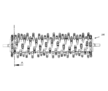
In Figure 1 a tool-holder rotor is designated by numeral 100. Tool
holders 20 are arranged on the tool-holder rotor 1. Each tool
holder 20 forms a seat for a tool 1. The tool holder 20 is
composed of a front portion in the working direction 21, a lower
portion 23 and a rear portion 22 including a through hole for a
bolt 30.
The tool 1 for grinders, mulchers and the like, is arranged in a
tool holder 20 for a tool-holder rotor 100 rotating about the axis
of the rotor. This tool 1 is received in a seat 21, 22, 23 of the
tool holder 20 on the tool-holder rotor 100. The seat 20 is formed
by a first surface 21 disposed in the cutting direction and a
second surface 22 upon which the tool is fastened with its
surface that faces away from the cutting direction. The tool 1 has
a body 2with a front surface 2a oriented in the direction of
rotation of the rotor, and a rear surface 2b that faces away from
the front surface 2a.
According to the invention, the rear surface 2b is inclined by an
angle of 1 to 10 with respect to the front surface 2a. This means
that the angle p, ranges from 182 to 190 .
The tool 1 is only clamped and supported between the surface
21 oriented in the cutting direction of the seat and the surface
that faces away 22 from the cutting direction of the seat, 1 a
clearance being left between the tool and the bottom of the seat
23.
Date Recue/Date Received 2024-01-12
5
The tool it is fastened at its top by means of a bolt 30 that
extends through the tool holder 20 in the surface 22 and is
tightened in the hole 31 of the tool.
Advantageously, the tool 1 has a recess on its rear surface 2b.
This recess is formed by a first upper portion substantially
parallel to the rear surface of the tool and a second lower portion
which is inclined toward the front surface by an angle of 10 to
90 , therefore, the angle a ranges from 190 to 270 . This
facilitates removal, as a backward rotation of the lower portion
of the tool can occur when the back of the tool head is loaded
with a force applied opposite to the direction of rotation of the
tool.
Furthermore, the central recess is complementary to a a raised
portion on the rear surface of the seat 22. This affords easier
and more accurate positioning.
The tool and the seat are made of steel and the cutting edge 3
is preferably made of special steel.
The bolt 31 for fastening the tool is preferably introduced from
the back in the tool holder seat. This avoids exposure of the bolt
head to processing wear, which might hinder its removal.
Figure 6 shows a tool holder 20 with a tool 1 received therein.
The cutting direction of 10 is designated by arrow 10. The tool 1
is clamped in the tool holder 20 at the contact area 11 between
the front portion of the tool holder 21 and the front surface of
the tool 2a, and at the contact area 12, between the rear portion
Date Recue/Date Received 202401-12
6
of the tool holder 22 and the rear surface of the tool 2b, with a
clearance 13 being left between the lower surface of the tool 2c
and the lower surface of the tool holder 23.
By this arrangement, as discussed above, the tool will not move
in the working direction because it is also locked by the bolt 30,
which prevents wear of the tool holder 20 and the bolt 30.
The tool is released by removing the bolt and hitting the back of
the tool 1 in the working direction 10.
It will be finally appreciated that the tool and tool holder as
described heretofore are susceptible of additions, changes or
variants that would be obvious to the skilled person, without
departing from the scope of the invention.
List of references
1 tool
2 tool body
2a front surface of the tool in the cutting direction
2b rear surface of the tool in the cutting direction
2c lower surface of the tool
3 cutting edge
cutting direction
11 contact area
12 contact area
13 clearance
tool holder
Date Recue/Date Received 202401-12
7
21 front portion of the tool holder
22 rear portion of the tool holder
23 lower portion of the tool holder
30 bolt
31 bolt hole in the tool body
100 tool-holder rotor
a angle of the rear surface of the tool
f3 angle between the front and rear surfaces of the tool
***
In some aspects, embodiments of the present invention as
described herein include the following items:
1. A tool for grinders and mulchers arranged in a tool holder
for a tool holder rotor rotatable about an axis of the tool
holder rotor; the tool being housed in a single seat of the
tool holder arranged on the tool holder rotor; the single
seat being formed by a front portion of the tool holder
provided in a cutting direction and a rear surface portion
of the tool holder onto which the tool is fixed; the front
portion of the tool holder contacts only a small bottom
surface portion of the tool whereas the rear surface
portion of the tool holder contacts a large surface portion
of the tool; a surface area of the large surface portion of
the tool contacted by the rear surface portion of the tool
holder being many times larger than a surface area of the
small bottom surface portion of the tool contacted by the
Date Recue/Date Received 202401-12
8
front portion of the tool holder; the tool is supported
exclusively between a small bottom surface portion of the
front portion of the tool holder in the cutting direction of
the single seat and the rear surface portion of the tool
holder; a single mechanism allowing easy removal of the
tool from the tool holder; the tool having a body which
has a front surface in the cutting direction of the tool
holder rotor contacted only by the small bottom surface
portion of the front portion of the tool holder, and a rear
surface opposite the front surface of the body, wherein
the rear surface is inclined in the range of 10 to 100 with
respect to the front surface; the tool is fitted and
supported between the front portion of the tool holder in
the cutting direction of the single seat and the rear
surface portion of the tool holder; and a clearance exists
between the tool and a bottom of the single seat.
2. The tool according to item 1, wherein the rear surface of
the tool has a recess and this recess comprises an upper
part and a lower part inclined 10 to 90' from the upper
part in the direction of the front surface of the tool.
3. The tool according to item 1, wherein the rear surface of
the tool has a recess and this recess is formed by a first
upper part substantially parallel to the rear surface of the
tool and a second lower part which is inclined in 100 to
Date Recue/Date Received 202401-12
9
900 from the first upper part in the direction of the front
surface of the tool.
4. The tool according to item 1, wherein the single
mechanism is a bolt through an upper part of the tool
holder.
Date Recue/Date Received 202401-12