Note: Descriptions are shown in the official language in which they were submitted.
CA 03034245 2019-02-15
WO 2018/034794 PCT/US2017/043318
WATER CONTAINER WITH FLOATABLE FILTER SYSTEM AND METHOD
TECHNICAL FIELD
[0001] The present disclosure is generally related to the field of water
filtration containers,
including water pitchers, having filters configured to provide filtered water.
BACKGROUND
[0002] Pitchers with an attachable water filter are frequently used by
consumers who wish to
filter tap water before drinking or use. Typical filters couple to a reservoir
that fixedly sits
within the water pitcher. These reservoirs, however, are usually relatively
small compared to the
amount of space available within the pitcher for carrying purified water. If,
however, the
reservoir is enlarged to increase the unfiltered water capacity of the
reservoir, the size of the
filtered water space decreases. Thus, conventional water filtration pitchers
require multiple fills
of the reservoir to fill the volume of the filtered water reservoir, which is
very time consuming,
frustrating, and can take up to 15 minutes or more.
[0003] Frustration over the long wait time for fully filling a water
pitcher, the small filtered
water reservoir compared to the pitcher size, and the requirement to fill the
unfiltered water
reservoir multiple times to get a fully filled filtered water reservoir has
existed since the first self-
filtering water pitchers with the unfiltered water reservoirs were launched by
Brita in the 1960s.
Companies such as Brita, Pur and Camelback have all attempted to solve these
problems in
different ways, but each commercially viable attempt still suffers from one or
more of the
problems of requiring multiple fills, reduced filtering of contaminants, and
slower fill or
dispensing of water because the filtering is being done while filling or
dispensing. Despite the
inherent problems with the original Brita design with its small unfiltered
water reservoir that
requires multiple fills to filter water to the larger filtered water
reservoir, that Brita pitcher design
still remains the top selling self-filtering water pitcher in the world.
SUMMARY
[0004] According to one aspect, a portable drinking water pitcher may
comprise a floatable
body surrounding a filter opening adapted to receive and engage a replaceable
water filter
therein, the floatable body having a seal extending outward of an outer
surface of the floatable
body, a pitcher having an upper end and a base opposite the upper end, the
base and the upper
1
CA 03034245 2019-02-15
WO 2018/034794 PCMJS2017/043318
end joined by an outer wall, the pitcher defining a first cavity, a removable
sleeve positioned
within the pitcher and extending from the upper end to proximate the base of
the pitcher, the
sleeve defining a second cavity within the pitcher and comprising one or more
sidewalls
continuously surrounding the second cavity, the sleeve having a top open end
and a bottom open
end, and a spout formed by the one or more sidewalls of the removable sleeve
and the outer wall
of the pitcher, the spout extending from adjacent the base of the pitcher to
adjacent the upper end
of the pitcher, the spout defining an exit opening located adjacent the upper
end and an inlet
opening located adjacent the base, wherein the inlet opening of the spout is
in fluid
communication with the bottom end of the sleeve and receives water from the
second cavity of
the sleeve, wherein the floatable body is disposed in the cavity with the seal
engaging the one or
more sidewalls to restrict water from passing between the floatable body and
the one or more
sidewalls as the floatable body moves from a raised position adjacent the top
end of the sleeve to
a lowered position adjacent the bottom open end of the sleeve, and wherein as
water is dispensed
through the spout, the floatable body auto-retracts towards the base while
maintaining the
engagement of the seal with the one or more sidewalls and an orientation of
the floatable body in
relation to the base as the pitcher is tipped to pour water from the spout.
[0005] Particular embodiments may comprise one or more of the following
features. The
auto-retraction of the floatable body may occur in reaction to a pressure
differential created
between air above the floatable body in the cavity and water below the
floatable body in the
second cavity. The auto-retraction of the floatable body may be in a direction
away from the exit
opening of the spout. The base of the pitcher may be located above the exit
opening of the spout
at the upper opening when the floatable body auto-retracts away from the upper
opening towards
the base when the pitcher is tipped to pour water from the spout. The seal of
the floatable body
may be located above the bottom end of the sleeve after the floatable body has
been auto-
retracted to the base. The floatable body may have a planar bottom surface and
the sleeve may
have a planar bottom surface, the planar surfaces located parallel to one
another and remain
parallel as the floatable body auto-retracts towards the base when the pitcher
is tipped to pour
water from the spout. The floatable body may fill a portion of the bottom open
end as the
floatable body auto-retracts towards the base. The top open end of the sleeve
may be proximate
the upper end of the pitcher and the bottom open end of the sleeve is in
contact with the base.
2
CA 03034245 2019-02-15
WO 2018/034794 PCMJS2017/043318
The second cavity may fill a majority of the first cavity. The first cavity
having a first volume
and the second cavity having a second volume, wherein the second volume may
fill at least 70%
of the first volume. The second volume fills at least 85% of the first volume.
One of the bottom
open end of the sleeve and the pitcher base may comprise a protrusion, and the
other of the
bottom open end of the sleeve and the pitcher base may be mated with the
protrusion. The
pitcher may engage the sleeve proximate at least one of the top open end and
the bottom open
end of the sleeve. A removable lid may be coupled to the upper end of the
pitcher and the top
open end of the sleeve. The floatable body having a volume within the
floatable body and the
second cavity having a volume within the second cavity, wherein the ratio of
the floatable body
volume to the second cavity volume may be within the range of 1/8 to 1/2. The
seal may have a
first portion configured to engage the floatable body and a second portion
extending outwardly
and configured to engage the one or more sleeve sidewalls and restrict water
from passing
between the floatable body and the one or more sleeve sidewalls. The second
portion may
comprise an arm, a distal tapered tip coupled to the arm, and a bridge coupled
to the arm through
a hinge portion opposite the tapered tip and also coupled to the first portion
opposite the hinge
portion. The hinge portion may be configured to allow the second portion to
bend about the
hinge portion such that the tapered tip engages the one or more sleeve
sidewalls at a second
angle relative to the floatable body when the floatable body rises, and a
first angle when the
floatable body lowers. The tapered tip may be configured to create friction
with the one or more
sleeve sidewalls, wherein the friction created when the floatable body rises
in the sleeve is
different from the friction created when the floatable body lowers in the
sleeve.
[0006] According to another aspect, a portable drinking water pitcher may
comprise a
floatable body surrounding a filter opening adapted to receive and engage a
replaceable water
filter therein, the floatable body having a seal extending outward of an outer
surface of the
floatable body, and a pitcher having an upper end, a sidewall defining a
cavity, a lid and a base
opposite the upper end, the pitcher further having an inner wall and an outer
wall defining a
channel, the channel including an exit opening located adjacent the upper end
and an inlet
opening located adjacent the base, wherein the floatable body is disposed in
the cavity with the
seal engaging the sidewall of the cavity to restrict water from passing
between the sidewall and
the floatable body as the floatable body moves between a first position and a
second position,
3
CA 03034245 2019-02-15
WO 2018/034794 PCMJS2017/043318
and wherein as water is dispensed through the exit opening of the channel, the
floatable body
auto-retracts away from the lid towards the base while maintaining the
engagement of the seal
with the sidewall and an orientation of the floatable body in relation to the
base as the pitcher is
tipped to pour water from the channel.
[00071 Particular embodiments may comprise one or more of the following
features. The
auto-retraction of the floatable body may be in a direction away from the exit
opening of the
channel. The base of the pitcher may be located above the exit opening of the
channel when the
floatable body auto-retracts away from the lid towards the base when the
pitcher is tipped to pour
water from the channel. The inner wall may have a terminal end that is spaced
a distance from
the base and define a passageway in fluid communication with the inlet opening
of the channel,
the floatable body may reduce the size of the passageway as the floatable body
auto-retracts
towards the base. The seal of the floatable body may be located above the
terminal end after the
floatable body has been retracted to the base. The floatable body has a planar
bottom surface and
the base has a planar bottom surface, the planar surfaces may be located
parallel to one another
and remaining parallel as the floatable body auto-retracts toward the base
when the pitcher is
tipped to pour water from the channel. The floatable body may further comprise
at least one
contact point on a surface of the floatable body that is vertically spaced
from the seal by more
than half a distance between a top surface of the floatable seal and a bottom
surface of the
floatable seal.
[00081 According to another aspect, a method of filtering water may
comprise disposing a
removable sleeve in a first cavity of a container, the container having a
handle, an upper end, a
pour lip, one or more pitcher sidewalls, and a pitcher base opposite the upper
end together
defining the first cavity, and the removable sleeve having an upper opening,
one or more sleeve
sidewalls, and a lower opening in the one or more sleeve sidewalls proximate a
lower end of the
sleeve opposite the upper opening together defining a second cavity, securing
an interchangeable
water filter within a filter opening of a floatable body, the floatable body
surrounding the filter
opening and having a seal extending outward of an outer surface of the
floatable body, disposing
the floatable body within the sleeve such that the seal is engaged with the
one or more sleeve
sidewalls and restricts water from passing between the floatable body and the
one or more sleeve
sidewalls while the floatable body remains moveable within the second cavity
between a first
4
CA 03034245 2019-02-15
WO 2018/034794 PCMJS2017/043318
position proximate the pitcher base to a second position proximate the sleeve
upper opening,
filling a portion of the second cavity above the floatable body with
unfiltered water deposited
through the upper opening, dispensing filtered water by tipping the pitcher,
pouring the filtered
water from the second cavity below the floatable body through a channel formed
by a void
between the container and the sleeve, the channel extending from the second
cavity through the
lower opening of the sleeve to the pour lip proximate the upper end of the
container, refilling the
portion of the second cavity above the floatable body with unfiltered water
after the all filtered
water has been dispensed and the floatable body has auto-retracted to the
first position in
response to the dispensing of all filtered water, wherein filtered water is
deposited into the
second cavity below the floatable body after passing through the water filter
as the floatable
body moves within the sleeve toward the second position in response to a first
pressure
differential within the second cavity created by water filtering from above
the floatable body to
below the floatable body, and wherein the floatable body auto-retracts toward
the first position,
while maintaining engagement with the one more sleeve sidewalls and relative
orientation in
relation to the pitcher base, in response to a second pressure differential
within the second cavity
created by pouring filtered water from the second cavity through the channel
by tipping the
pitcher, wherein the auto-retraction toward the first position is concurrent
with the pouring of
filtered water and in a direction opposite a direction of the filtered water
moving through the
channel to the pour lip.
[0009] Particular embodiments may comprise one or more of the following.
Coupling a
removable lid to the upper end and the upper opening. One of the lower end of
the sleeve and
the pitcher base may comprise a protrusion, and wherein disposing the
removable sleeve in the
first cavity of the container further may comprise mating the other of the
lower end of the sleeve
and the pitcher base with the protrusion.
[0010] Aspects and applications of the disclosure presented here are
described below in the
drawings and detailed description. Unless specifically noted, it is intended
that the words and
phrases in the specification and the claims be given their plain, ordinary,
and accustomed
meaning to those of ordinary skill in the applicable arts. The inventors are
fully aware that they
can be their own lexicographers if desired. The inventors expressly elect, as
their own
lexicographers, to use only the plain and ordinary meaning of terms in the
specification and
claims unless they clearly state otherwise and then further, expressly set
forth the "special"
definition of that term and explain how it differs from the plain and ordinary
meaning. Absent
such clear statements of intent to apply a "special" definition, it is the
inventors' intent and
desire that the simple, plain and ordinary meaning to the terms be applied to
the interpretation
of the specification and claims.
[0011] The inventors are also aware of the normal precepts of English
grammar. Thus, if
a noun, term, or phrase is intended to be further characterized, specified, or
narrowed in some
way, then such noun, term, or phrase will expressly include additional
adjectives, descriptive
terms, or other modifiers in accordance with the normal precepts of English
grammar. Absent
the use of such adjectives, descriptive terms, or modifiers, it is the intent
that such nouns,
terms, or phrases be given their plain, and ordinary English meaning to those
skilled in the
applicable arts as set forth above.
[0012] The invention is not limited only to the specific structure,
material or acts that are
described in the preferred embodiments, but in addition, include any and all
structures, materials
or acts that perform the claimed function as described in alternative
embodiments or forms of
the disclosure, or that are well known present or later-developed, equivalent
structures, material
or acts for performing the claimed function.
6
Date Recue/Date Received 2021-11-15
[0013] The foregoing and other aspects, features, and advantages will be
apparent to those
artisans of ordinary skill in the art from the DESCRIPTION and DRAWINGS.
BRIEF DESCRIPTION OF THE DRAWINGS
[0014] The disclosure will hereinafter be described in conjunction with the
appended
drawings, where like designations denote like elements.
[0015] FIG. 1 is a perspective view of a first embodiment of a floatable
seal and filter;
[0016] FIG. 2 is a cross-sectional view of a first embodiment of a
floatable seal taken along
line A-A of FIG. 1 and placed in a container;
[0017] FIG. 3 is an exploded view of a second embodiment of a drinking water
filter
system;
[0018] FIG. 4 is a partial cross-sectional view of a second embodiment of a
drinking water
filter system;
[0019] FIG. 5 is a perspective view of a second embodiment of a floatable
seal;
[0020] FIG. 6 is a cross-sectional view of a floatable seal taken along
line B-B in FIG. 5
and positioned within a filter sleeve;
[0021] FIG. 7 is an exploded view of third embodiment of a drinking water
filter system;
[0022] FIGs. 8A and 8B are perspective views of an embodiment of a lid having
a knob;
[0023] FIGs. 9A and 9B are perspective views of an embodiment of a lid having
a slider
piece;
[0024] FIG. 10A and 10B are perspective views of an embodiment of a lid having
a biased
flap;
[0025] FIG. 11A is a perspective view of a first embodiment of a floatable
seal having a
keyed feature;
[0026] FIG. 11B is a perspective view of a first embodiment of a filter
having a key channel;
[0027] FIG. 12A is a perspective view of a second embodiment of a filter
having a key
channel; and
[0028] FIG. 12B is perspective view of a second embodiment of a filter
having a keyed
feature.
7
Date Recue/Date Received 2021-11-15
CA 03034245 2019-02-15
WO 2018/034794 PCMJS2017/043318
[0029] Figure 13 is a perspective view of a water pitcher having a
floatable water filtering
body;
[0030] Figures 14-19 illustrate different views of the water pitcher of
FIG. 13;
[0031] Figures 20 illustrates the floatable body at the base of the cavity
immediately after
unfiltered water is poured into the cavity;
[0032] Figure 21 illustrates the floatable body as it rises in the cavity
during filtering of the
water;
[0033] Figure 22 illustrates the floatable body after it rises to the top
of the cavity and the
unfiltered water is filtered;
[0034] Figures 23-25 illustrate enlarged portions of FIGs. 20-22;
[0035] Figure 26 illustrates an exploded view of the floatable body;
[0036] Figures 27-30 illustrate different views of the y-ring;
[0037] Figure 31 illustrates the pitcher when initially tipped to dispense
filtered water;
[0038] Figure 32 illustrates the pitcher as filtered water is dispensed;
[0039] Figure 33 illustrates the pitcher after all filtered water has been
dispensed, showing
that the floatable body auto-retracts toward the pitcher base;
[0040] Figures 34-36 illustrate enlarged portions of FIGs 31-33;
[0041] Figure 37 illustrates the floatable body including the water filter;
[0042] Figures 38-44 illustrate various views of the floatable body of FIG.
37;
[0043] Figure 45 illustrates an exploded view of the floatable body;
[0044] Figure 46 illustrates the insertion of the water filter by rotation
into the floatable body
member;
[0045] Figure 47 illustrates a perspective view of the water filter;
[0046] Figures 48-54 illustrate different views of the contoured water
filter;
[0047] Figure 55 is a perspective exploded view of a water pitcher having a
floatable water
filtering body and a sleeve;
[0048] Figures 56-59 illustrate different views of the water pitcher of
FIG. 55; and
[0049] Figures 60-62 illustrate cross-sectional views of the water pitcher
of FIG. 55 with the
floatable water filtering body in different positions.
8
CA 03034245 2019-02-15
WO 2018/034794 PCMJS2017/043318
DETAILED DESCRIPTION
[0050] This disclosure, its aspects and implementations, are not limited to
the specific
components or assembly procedures disclosed herein. Many additional components
and
assembly procedures known in the art consistent with the intended water filter
system and/or
assembly procedures for a water filter system will become apparent for use
with implementations
of water filter systems from this disclosure. Accordingly, for example,
although particular
containers, seals, and filters are disclosed, such containers, seals, and
filters and implementing
components may comprise any shape, size, style, type, model, version,
measurement,
concentration, material, quantity, and/or the like as is known in the art for
such water filter
systems and implementing components, consistent with the intended operation of
a water filter
system.
[0051] Various embodiments of water filter systems contemplated as part of
this disclosure
are advantageous to water filter systems previously known in the art because
the systems
eliminate wasted space often present in conventional water filter systems. For
example,
conventional water filter systems include a reservoir that holds unfiltered
water as it is filtered
into a pitcher. When all or most of the water is unfiltered and in the
unfiltered reservoir, the
pitcher is empty or nearly empty, and thus wasted space. Conversely, when all
or most of the
water is filtered and in the pitcher, the unfiltered reservoir is empty or
nearly empty, and thus
wasted space. In essence, then, from 30% - 50% of conventional water filter
systems is empty or
wasted space. This space is critical in a refrigerator or dining area. In
contrast to these
conventional water filter systems, various embodiments of the water filter
system contemplated
as part of this disclosure eliminate substantially all empty or wasted space
in the system through
use of a floatable seal.
[0052] FIG. 1 depicts a non-limiting embodiment of a floatable seal 50
surrounding a
replaceable water filter 40. In the non-limiting embodiment depicted in FIG.
1, the filter 40 is
positioned substantially central on the floatable seal 50. In other
embodiments, the filter 40 may
be positioned elsewhere on the floatable seal 50. In particular embodiments,
due to balance
concerns, it may be advantageous to position the filter in substantially the
balance center of the
floatable seal 50 so that it moves upward as it filters more evenly. The
filter 40 is configured to
filter unfiltered water positioned above, in relation to gravity, the
floatable seal 50 through the
9
CA 03034245 2019-02-15
WO 2018/034794 PCMJS2017/043318
filter 40 to an area below the filter 40. In one or more embodiments, no
additional force beyond
the force of gravity is required for the unfiltered water to pass through the
filter 40. The filter 40
may comprise any filter previously known in the art and adapted to couple to
the floatable seal
50. In one or more embodiments, the filter 40 comprises a charcoal filter or
any other known
water-filtering device. The specific type of water filter used is not critical
to the embodiments
illustrated herein unless otherwise indicated. More particular embodiments may
comprise a filter
40 having a filth or exhaustion indicator that indicates the approximate life
of the filter 40 or
when the filter 40 needs replacements. According to another aspect, the filter
40 may be
configured to measure and display the temperature of the water within the
container.
[0053] One or more embodiments of a filter 40 may be fixedly or removably
coupled to the
floatable seal 50 according to various aspects of the water filtering system
contemplated herein.
As depicted in the non-limiting embodiment depicted in FIG. 2, the filter 40
is sized to rest upon
a ledge or lip 44 on a filter opening 36 extending at least partially through
the body 38 of the
floatable seal 50. In this and other embodiments, the filter 40 is adapted for
simple efficient
removal and replacement of the replaceable water filter 40 associated with the
seal 50. In one or
more embodiments, the filter 40 may comprise a filter ring 41 extending from
the filter 40 and
positioned to engage with the lip 44 on the filter opening 36 Such engagement
holds the filter
40 in place and allows water to pass from above the floatable seal 50 to below
the floatable seal
50 only through the filter 40.
[0054] The floatable seal 50 may comprise any shape complementary to the shape
of the
container 49 with which the floatable seal 50 will be utilized. In the
particular non-limiting
embodiment depicted in FIG. 1, the floatable seal 50 is substantially
cylindrical in shape. The
floatable seal 50, then, is configured for use within a substantially
cylindrical container 49 such
as a pitcher or cup. Pitchers are typically larger than cups. In other
embodiments, the floatable
seal 50 may comprise any shape complementary to the shape of the container 49
with which the
floatable seal 50 is utilized, including but not limited to oval, triangular,
square, or any other
polygonal shape (when viewed from above or below).
[0055] FIG. 2 depicts a cross-sectional view of a non-limiting embodiment
of a floatable seal
50 positioned within a container 49, the floatable seal 50 having a filter 40
mounted therein. In
one or more embodiments, the floatable seal 50 comprises a filter body 38
comprising a filter
CA 03034245 2019-02-15
WO 2018/034794 PCT/US2017/043318
opening 36 extending therethrough that is sized to receive the filter 40. The
filter opening 36
may comprise a ring 41 or alternatively may narrow to allow mounting of the
filter 40 therein.
[0056] As previously referenced, the seal typically comprises a floatable
seal 50. In the non-
limiting embodiment depicted in FIG. 2, the floatable seal 50 comprises a
floatable body 38
housing a gas-filled annular chamber 42 therein filled with air or other gas
such as, without
limitation, helium, hydrogen, oxygen or nitrogen. In one or more embodiments,
the annular
chamber surrounds the filter opening 36 of the floatable seal 50. In other
embodiments, the
floatable seal 50 comprises a plurality of chambers comprising any shape that
allows the
floatable seal 50 to float on the filtered water after the water has passed
through the filter 40. In
particular embodiments, the plurality of chambers is disposed evenly around
the floatable seal 50
to balance the floating characteristics of the floatable seal 50 In particular
embodiments, the
annular chamber 42 may comprise pressurized gas therein. In still other
embodiments, a floatable
material such as foam may replace or be used in combination with one or more
chambers on the
floatable seal 50. In particular embodiments, the chamber 42 is airtight.
[00571 As depicted in the non-limiting embodiments depicted in FIGs. 1 and
2, the floatable
seal 50 may further comprise one or more sealing rings 46 extending outward
from an outer
surface 47 of the floatable seal 50. In particular embodiments, the floatable
seal 50 comprises
one more sealing rings 46 positioned on an upper portion of the outer surface
47 of the floatable
seal 50 and one or more sealing rings 46 positioned on a lower portion of the
outer surface 47 of
the floatable seal 50. Even more particularly, the one or more rings may be
positioned on an
annular arm 48 extending from the floatable seal 50. In some embodiments, an
annular arm 48
extends angularly from the body 38 of the floatable seal, a channel 34 being
formed between the
annular arm 48 and the body 38 of the floatable seal 50. According to one
aspect, the floatable
seal 50 comprises an upper annular arm 48 and a lower annular arm 48, each
annular arm 48
comprising one or more sealing rings 46. According to other aspects, the
floatable seal 50
comprises only one of the upper or lower annular arms 48. In one or more
embodiments, an
annular arm 48 is biased away from the floatable seal 50. The one or more arms
48 and/or the
rings 46 are configured and positioned on the floatable seal 50 to restrict
unfiltered water held
above the floatable seal 50 from passing between the floatable seal 50 and the
wall of the
container 49 into the area of the container below the seal.
11
CA 03034245 2019-02-15
WO 2018/034794 PCT/US2017/043318
[00581 As illustrated by FIG. 2, the floatable seal 50 includes a first
point, line or surface
(collectively "point") at which the floatable seal 50 contacts the side of the
pitcher 49, and a
second point (point, line or surface), below the first point, that is more
than half the distance
between the top and the bottom of the floatable seal 50 away from the first
point that acts as a
balance point for the floatable seal 50. By including the seal contact point
and a second point
vertically offset from the seal that is positioned so that it may contact the
sidewall of the pitcher,
the float is able to maintain its relative orientation in relation to the
pitcher bottom. The second
point may be in contact with the side of the pitcher or sleeve, as with the
example in FIG. 2 or
the example in FIGs. 4-7 (balance tabs 22). Alternatively, the second point
may include a gap
between the second point and the pitcher or sleeve sidewall so that it is not
in constant, direct
contact with the side wall of the pitcher or sleeve but is available to
contact the side if needed to
maintain the relative orientation of the float in relation to the pitcher
bottom, as with the example
of FIGs. 20-22, the example of FIGs. 31-33, and the example of FIGs. 60-62. To
reduce friction
between the parts of the filter float and its surrounding surfaces, the filter
float may be
constructed so that only the seal contacts the surrounding surfaces. By
including a slight gap, the
filter float seal is able to more readily move up and down, and maintain the
orientation of the
filter float in the pitcher if the pitcher is tipped or if the filter float is
poked or pressure is applied
unevenly to the float, such as water pouring into the cavity and contacting
only one side of the
float.
[0059] As depicted in FIG. 2, the container 49 typically comprises a shape
complimentary to
the shape of the floatable seal 50. For example, in the non-limiting
embodiment depicted in FIG.
2, both the container 49 and the outer boundary of the seal are substantially
cylindrical in shape.
In other embodiments, the container 49 may comprise any shape complementary to
the shape of
the floatable seal 50 such that the floatable seal 50 is slidable within the
wall or walls of the
container 49 and still restricts or in some cases prevents passage of water
between the floatable
seal and the wall or walls of the container 49. The container 49 is likewise
sized to allow sliding
of the floatable seal 50 within the container 49 and maintaining the floatable
seal 50 between the
floatable seal 50 and the wall or walls of the container 49. Typically, the
walls of the container
49 are substantially vertical or perpendicular to the base of the container
49. Thus, the portion
of the container 49 that interfaces with the floatable seal 50 comprises a
unifoim diameter or
12
CA 03034245 2019-02-15
WO 2018/034794 PCT/US2017/043318
width that allows for the combination sliding and sealing features described
above. According to
some aspects, the cylindrical nature of the floatable seal 50 and/or the
annular arms 48 of the
floatable seal 50 discourage the floatable seal 50 from tipping once the
floatable seal 50 is within
the container 49.
[0060] The floatable seal 50 may be made of any of a variety of materials.
In one or more
embodiments, the floatable seal 50 comprises a plastic seal. More
particularly, the floatable seal
50 comprises plastic pieces sonically welded, adhesively glued, compression
fit or otherwise
coupled to one another. In particular, non-limiting embodiments, the floatable
seal 50 or any
floatable seal disclosed herein may comprise polypropylene, as well as a float
overmold
comprising a theinioplastic elastomer (TPE) or GLS Versaflex TM CL. The
annular arm 48 and/or
sealing rings 46 may likewise be plastic or, alternatively, a rubber material.
In still other
embodiments, the floatable seal 50 comprises a rubber or silicon seal. The
container 49 of this
embodiment or any other containers, pitchers, cups, and the like disclosed
herein may be made of
any of a variety of materials known in the art, such as but not limited to
plastic, metal, wood,
glass, rubber, polycarbonate, clear acrylic, and the like. Any of the
containers disclosed herein
may further comprise a pitcher overmold comprising TPE and/or GLS VersaflexTM
OM. In one
or more embodiments, the container comprises a spout or straw extending
outward from the base
of the container 49. Alternatively, the container 49 may comprise an opening
at the base of the
container 49 configured to receive a straw or spout. The container 49 may
further comprise a
plug that plugs the spout or straw during filtration. Through the inclusion of
a spout or straw
opening from the base of the container 49, the filtered water may be poured or
sucked out of the
container 49 while unfiltered water is still passing through the filter 40.
[0061] In operation, a method of filtering water may utilize embodiments of
the floatable seal
50 and container 49 disclosed herein. The floatable seal 50 is typically
placed into the container
49. The filter 40 may be mounted or coupled to the floatable seal 50 prior to
placing the
floatable seal 50 in the container 49 or after placing the floatable seal 50
in the container 49. The
floatable seal 50 may be placed on the bottom of the container 49 when it is
empty or,
alternatively, placed on filtered water already present in the container 49.
The floatable seal 50 is
positioned such that a seal is formed between the walls of the container 49
and the floatable seal
13
CA 03034245 2019-02-15
WO 2018/034794 PCT/US2017/043318
50. In such positioning, typically the only fluid communication between the
area above the
floatable seal 50 and the area below the floatable seal 50 is through the
filter 40.
[0062] Once the floatable seal 50 is positioned appropriately in the
container 49, unfiltered
water is poured into the container. The floatable seal 50 may be positioned
approximately 0.25 ¨
1.0 inches above the bottom base of the container 49 in particular
implementations to provide
additional space for the initial filtered water to filter prior to the
filtered water starting to float the
seal. In some embodiments, a spacer component may be coupled to or integrated
into the design
of the floatable seal 50 to establish the gap between the floatable seal 50
and the bottom surface
of the base inside of the container 50. In yet other embodiments, as
illustrated in the structure of
the floatable seal 50 in FIG. 2, the floatable seal 50 may be placed adjacent
to the bottom surface
of the base inside of the container 49 and a gap between the filter 40 and the
bottom of the body
38 floatable seal 50 allows filtered water to start to float the floatable
seal 50.
[00631 The floatable seal 50 and filter hold the unfiltered water in the
unfiltered chamber or
area above the floatable seal 50 as the unfiltered water passes through the
filter 40. Water passes
from the area above the filter 40 to the area below the floatable seal 50 only
through the filter 40,
and not between the floatable seal 50 and walls of the container 49. As the
water passes through
the filter 40, the floatable seal 50 floats on the filtered water below the
floatable seal 50 and is
biased through the water above it to float above that water too, thus
increasing the volume of the
area below the floatable seal 50 and decreasing the volume of the area above
the floatable seal
50. Once all the water above the floatable seal 50 has passed through the
floatable seal 50, the
floatable seal 50 and filter 40 may be removed from the container 49. In other
embodiments, a
spout may be included within the container 49 extending from the bottom of the
container 49 so
that water may be poured from the container 49 without removal of the
floatable seal 50 and
filter 40.
[00641 According to some aspects, a water filter system may be further
configured to
comprise a filter sleeve 20 in addition to a floatable seal 30 and filter 40.
In particular, FIG. 3
depicts an exploded view of a non-limiting embodiment of a water filter system
10 comprising a
pitcher 2, a filter sleeve 20, a floatable seal 30, and a lid 60. The
floatable seal 30 and filter 40
may comprise any of the floatable seals and filters and their characteristics
and alternatives as
described elsewhere in this document.
14
CA 03034245 2019-02-15
WO 2018/034794 PCT/US2017/043318
[00651 The pitcher 2 may comprise any container known in the art or
described elsewhere in
this document and adapted for use with a filter sleeve 20. In one or more
embodiments, the
pitcher 2 comprises one or more walls 4 forming a chamber 7 sized to house the
filter sleeve 20
therein, a base 6, and a sleeve opening 9 distal the base 6. The sleeve
opening 9 is sized and
configured to allow at least a portion of the filter sleeve 20 to pass through
the sleeve opening 9.
According to some aspects, the pitcher 2 is configured to allow mounting of
the filter sleeve 20
thereto. The sleeve opening 9 is typically bordered by the rim 8 that
interfaces with mounting lip
16 on the filter sleeve 20 to mount the filter sleeve 20 within the sleeve
opening 9. More
particularly, the pitcher 2 may comprise a rim 8 proximate the filter opening
9. According to
some aspects, the rim 8 is formed integral with a pitcher lid 3. The pitcher
lid 3 may be integral
with the walls 4 of the pitcher 2 or, alternatively, may be removably coupled
to the wall 4
opposite the base 6. Additional threading or locking tabs may border the
sleeve opening 9 for
removable coupling of filter sleeve 20 to the pitcher lid 3. The pitcher may
further comprise a
spout opening, or pouring lip, extending at least partially through the
pitcher lid 3. In still other
embodiments, the rim 8 may be formed without a pitcher lid 3.
[00661 FIGs. 3 and 4 also depict a non-limiting embodiment of a filter
sleeve 20. The filter
sleeve 20 typically comprises a hollow sleeve with a first or bottom open end
11 and a second or
top open end 12 opposite the first open end 11 and in fluid communication with
the first open
end 11. The filter sleeve 20 may comprise a variety of shapes formed by one or
more walls 13 of
the filter sleeve 20, such as but not limited to a cylindrical sleeve as
depicted in FIGs. 3 and 4. In
other embodiments, the cross-sectional shape of a filter sleeve may comprise
an oval, a triangle,
a rectangle, a square, a pentagon, and so on. The filter sleeve 20 is
typically shaped
complementary to the shape of the sleeve opening 3 in the pitcher 2. In one or
more
embodiments, the inner surface 18 of the walls 13 of the filter sleeve
comprise zero-draft walls.
[00671 As noted above, one aspect of a filter sleeve 20 comprises a
mounting lip 16 proximate
a second or top end 12 of the of the filter sleeve 20 The mounting lip 16 is
positioned on the
filter sleeve 20 such that when the mounting lip 16 is interfacing or engaging
with the rim 8 of
the pitcher 2, the bottom or first end 11 of the filter sleeve 20 is not in
direct contact with the
base 6 of the pitcher 2. That is, a space exists between the bottom end 11 of
the filter sleeve 20
and the base 6 of the pitcher when the mounting lip 16 is engaged with the rim
8 of the pitcher 2
CA 03034245 2019-02-15
WO 2018/034794 PCT/US2017/043318
or otherwise removably coupled to the pitcher lid 3. The mounting lip 16 may
extend outward
from the outer surface of the one or more walls 13 of the filter sleeve 20 and
may surround the
entire outer surface of the filter sleeve 20. In other embodiments, the
mounting lip 16 comprises
a plurality of mounting lips extending outward from the outer surface of the
wall 13 of the filter
sleeve 20 to hold the filter sleeve 20 suspended within the pitcher 2. The
mounting lip 16 is
typically sized and positioned to interface with the rim 8 of the pitcher 2.
In some embodiments,
the filter sleeve 20 may comprise threading or tabs for engaging with
threading or tabs on the
pitcher lid 3. The mounting lip 16 itself may engage with tabs or threading on
the pitcher lid 3.
[0068] One or more embodiments of a filter sleeve 20 further comprise
sleeve threading or
tabs proximate the top end of the sleeve. The threading or tabs proximate the
top end 12 of the
filter sleeve 20 are typically configured to engage with threading or tabs on
the sleeve lid 60 for
removable coupling of the sleeve lid 60 to the filter sleeve 20. According to
one aspect, the
threading or tabs of the filter sleeve 20 are positioned between the top end
12 of the filter sleeve
20 and the mounting lip 16 of the filter sleeve 20.
[0069] One or more embodiments of a filter sleeve 20 further comprise a
stop lip 14
proximate a first or bottom end 11 of the filter sleeve 20. FIG. 4 depicts a
cross-sectional view
of a non-limiting embodiment of water filter system 10, including a filter
sleeve 20 comprising a
stop lip 14. According to some aspects, the stop lip 14 extends inward from an
inner surface 18
of the one or more walls 13 of the filter sleeve 20. The stop lip 14 is sized
to engage with the
floatable seal 30 and restrict the floatable seal 30 from sliding from the
filter sleeve 20 into the
pitcher 2.
[0070] The inner surface 18 of the wall(s) 13 of the filter sleeve 20 are
typically smooth
between the top end 12 and the stop lip 14 of the filter sleeve 20 to allow
sliding of the floatable
seal 30 between the top end 12 and the bottom end 11 of the filter sleeve 20.
In one or more
embodiments, the inner surface 18 of the filter sleeve 20 may comprise tracks
configured to align
with slots on the floatable seal 30. The filter sleeve 20 and the water
pitcher 2 are formed
separately and later assembled.
[0071] FIGs. 5 and 6 depict a non-limiting embodiment of a floatable seal
30. The floatable
seal 30 is configured to slide within in the filter sleeve 20 between the top
end 12 and the bottom
end 11. More particularly, the floatable seal 30 is configured to float on
water within the pitcher
16
CA 03034245 2019-02-15
WO 2018/034794 PCT/US2017/043318
2 and rise within the filter sleeve 20 above the bottom end 11 of the filter
sleeve 20 when the
water level within the pitcher 2 is above the bottom end 11 of the filter
sleeve 20. The floatable
seal 30 is also configured to removably couple or mount to a water filter 40.
When a water filter
40 is mounted to the floatable seal 30, the floatable seal 30 is positioned
within the filter sleeve
20, and water is held within the filter sleeve 20 above the floatable seal 30,
the floatable seal 30
is configured to restrict water from passing between the outer surface 23 of
the floatable seal 30
and the inner surface 18 of the walls 13 of the filter sleeve 20. Instead, the
floatable seal 30 is
configured to allow water to only pass from the filter sleeve 20 to the
pitcher 2 through the water
filter 40.
[00721 The floatable seal 30 is typically shaped complimentary to the shape
of the filter
sleeve 20. For example, in the non-limiting embodiment depicted in FIGs. 3 and
4, the floatable
seal 30 is substantially cylindrical in shape to complement the cylindrical
channel of the filter
sleeve 20. In one or more embodiments, the floatable seal 30 comprises a
plurality of balance
tabs 22 positioned on an outer surface 23 of the floatable seal 30. The
plurality of balance tabs
22 are sized to interface with the inner surface 18 of the wall 13 of the
filter sleeve 20. The
balance tabs 22, like other second contact points in other embodiments,
discourage the floatable
seal from tipping or wobbling within the filter sleeve 20, while also
decreasing the amount of
surface area of the floatable seal 30 in contact with an inner surface 18 of
the filter sleeve 20.
Decreasing the surface area in contact with the inner surface 18 of the filter
sleeve 20 reduces the
friction between the floatable filter 30 and the filter sleeve 20, thus
allowing for easier sliding
motion of the floatable filter 30 within the filter sleeve 20. The floatable
seal 30 may further
comprise a concave portion between the top and bottom of the floatable seal
30, for example and
without limitation, as illustrated in FIGs. 5 and 6.
[00731 The floatable seal typically further comprises a sealing ring 24
sized and positioned to
interface with the inner surface 18 of the wall 13 of the filter sleeve 20. In
the non-limiting
embodiment shown in FIGs. 5 and 6, the sealing ring 24 is proximate a top of
the floatable seal.
In other embodiments, the sealing ring 24 may be positioned elsewhere on the
floatable seal 30,
such as but not limited to a bottom portion or a central portion. FIG. 6
depicts a cross-sectional
view of a floatable seal 30 having a sealing ring 24. According to some
aspects, the sealing ring
24 comprises a rubber seal either fixedly or removably coupled to the
floatable seal 30. In some
17
CA 03034245 2019-02-15
WO 2018/034794 PCT/US2017/043318
embodiments, the sealing ring 24 is over-molded to the floatable seal 30. The
sealing ring 24 is
configured to restrict water from passing between the outer surface 23 of the
floatable seal 30
and the inner surface 18 of the wall 13 of the filter sleeve 20. The sealing
ring 24 is also
configured to allow the floatable seal 30 to slide within the filter sleeve 20
while simultaneously
restricting the passage of water between the outer surface 23 of the floatable
seal 30 and the
inner surface 18 of the walls 13 of the filter sleeve 20. According to some
aspects, the floatable
seal comprises a plurality of sealing rings 24. The sealing ring 24 may
comprise a rubber,
plastic, or any other suitable material.
[0074] Aspects of the floatable seal 30 may further comprise any of the
other elements of a
floatable seal described elsewhere in this document relating to other
embodiments of a floatable
seal. For example, the floatable seal 30 may comprise a filter opening 28 and
ledge or lip for
coupling and mounting of the filter 40 to the filter opening 28 According to
some aspects, the
floatable seal 30 may comprise an over-molded seal positioned on the lip
around the filter
opening 28. The over-molded seal is configured to restrict water from seeping
between the filter
40 and the floatable seal 30. In other aspects, the filter 40 may be
threadedly coupled to the
floatable seal 30. In still other embodiments, the floatable seal 30 may
comprise a textured,
ribbed, or other non-planar surface, particularly at the lip adjacent the
filter opening 28. The
filter 30 may comprise complementary texturing, ribbing, or other non-planar
surfacing to form a
seal between the filter 40 and the floatable seal. In these or other
embodiments, the filter 40 may
snap-fit to the floatable seal 30.
[0075] Additionally, as the floatable seal 30 is configured to float on
water, the floatable seal
30 may comprise any of the configurations or materials described elsewhere in
this document
that allow the floatable seal to float on water, such as but not limited to a
gas-filled chamber 25.
In any of the embodiments described herein, the floatable seal 30 may be
configured such that
the filter 40 is offset or not planar with the bottom of the floatable seal
30. In this way, the filter
40 stays out of the filtered water below the floatable seal 30.
[0076] In operation, the floatable seal 30 and filter 40 may rest anywhere
within the filter
sleeve 20 when no water is held within the filter sleeve 20 above the
floatable seal 30 and filter
40. According to some embodiments, the floatable seal 30 and filter 40 rest on
either the water
within the pitcher 2 or the stop lip 14, whichever is lower, when no water is
held within the filter
18
CA 03034245 2019-02-15
WO 2018/034794 PCT/US2017/043318
sleeve 20 above the floatable seal 30 and filter 40. As water is added to the
filter sleeve 20
above the floatable seal 30 and filter 40, water begins to pass from the
filter sleeve 20 to the
pitcher 2 only through the filter 40. As water passes from the filter sleeve
20 to the container
through the filter 40, the water level within the pitcher 2 rises and the
floatable seal 30 floats on
the water within the pitcher 2 and filter sleeve 20. Thus, the floatable seal
30 rises within the
filter sleeve 20 as the water in the pitcher 2 rises.
[0077] Embodiments of the floatable seal systems contemplated as part of
this disclosure are
configured to filter water at various rates. For example, some of the filters
40 are configured to
filter approximately IA to approximately 3 cups of water per minute. More
particularly, some of
the filters 40 are configured to filter approximately 1 to 3 cups of water per
minute. Even more
particularly, some of the filters 40 are configured to filter approximately 1
cup of water per
minute
[0078] As depicted in the non-limiting embodiment of FIG. 3, various
embodiments of a
water filter system further comprise a sleeve lid 60. The sleeve lid 60 is
typically configured to
removably couple to either the container lid 3 or the filter sleeve 20. In the
non-limiting
embodiment of FIG. 3, the sleeve lid 60 is configured to removably and
threadedly couple to the
filter sleeve 20. According to some embodiments, the filter sleeve 20 further
comprises one or
more openings 56 and a funnel-shaped portion 58 that allow a user to insert
water into the filter
sleeve 20 without removing the sleeve lid 60. The one or more openings may
covered by a
biased flap, as depicted in the non-limiting embodiment of FIG. 10.
[0079] FIG. 7 depicts other non-limiting embodiments of a sleeve lid 62,
floatable seal 30,
and a filter sleeve 64. While in the non-limiting embodiment of FIG. 3 the
sleeve lid 60
threadedly couples with an outer surface of the filter sleeve 20, in the non-
limiting embodiment
of FIG. 5, the sleeve lid 62 is configured to threadedly couple to the
interior surface 65 of the
filter sleeve 64. For example, the floatable seal 30 may be inserted into the
filter sleeve 64, and
then a threaded portion 78 at an open first or top end 74 of the lid 62 may be
threadedly coupled
to a threaded portion 76 on the interior surface 65 of the filter sleeve 64.
[0080] Some embodiments, such as the embodiment depicted in FIG. 7,
comprise a filter
sleeve 64 configured to removably couple to another apparatus, such as but not
limited to a water
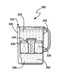
bowl for a pet. For example, an open second or bottom end 72 of the filter
sleeve 64 may
19
CA 03034245 2019-02-15
WO 2018/034794 PCT/US2017/043318
removably couple to a pet dish. In operation, the floatable seal 30 and filter
sleeve 64 may be
configured similar to and work similar to those described elsewhere in this
document.
[0081] According to some embodiments, a sleeve lid comprises a funnel shaped
portion and a
plurality of small holes at the base of the funnel shaped portion. This
configuration allow for
water to be more easily inserted into the filter sleeve. According to some
aspects, the center
portion of the filter cap is movable between to positions to either open or
close the plurality of
small holes. FIGs. 8A and 8B depict another non-limiting embodiment of a
sleeve lid 80. In this
particular embodiment, the sleeve lid 80 comprises a funnel-shaped portion 86.
This particular
embodiment further comprises a knob 82 on the sleeve lid 80 that is movable
between two
positions. When the knob 82 is pulled up to a first position (shown in FIG.
8A), water is allowed
to pass through the sleeve lid 80. When the knob 82 is pushed down to a second
position (shown
in FIG. 8B), water is restricted from passing through the sleeve lid 80. When
the knob 82 is
pushed down and the rotated, the sleeve lid 80 may be removed. The sleeve lid
80 may be
adapted for use with any of the water filter systems described in this
document.
[00821 FIGs. 9A and 9B depict another non-limiting embodiment of a sleeve
lid 100. In this
particular embodiment, the sleeve lid 100 comprises a slider piece 102. The
slider piece 102 is
configured to cover the spout exit of the pitcher when the opening 104 on the
sleeve lid 100 is
uncovered to allow unfiltered water to enter the filter sleeve 20. When the
slider piece 102 is
slide to cover the opening 104, the spout exit is uncovered to allow filtered
water to be poured
from the container to a cup through the spout. The sleeve lid 100 may further
comprise a
depression that may be used to rotate the sleeve lid 100 from a locked to an
unlocked position.
The sleeve lid 100 may be adapted for use with any of the water filter systems
described in this
document.
[0083] FIGs. 10A and 10B depict another non-limiting embodiment of a sleeve
lid 90. In this
non-limiting embodiment, the filter lid 90 comprises a funnel shaped portion
96. At the base of
the funnel shaped portion 96 is a biased flap 92. The biased flap 92 closes an
opening 94 in the
filter lid 90 unless a force is exerted on the biased flap 92. When water from
a faucet comes in
contact with the biased flap 92, the force is typically strong enough to push
the biased flap 92
down to uncover the opening 94 and allow water to enter the filter sleeve 20.
The filter lid 90
CA 03034245 2019-02-15
WO 2018/034794 PCT/US2017/043318
may further comprise raised nubs to allow a user to screw on and off the lid
90. The sleeve lid
90 may be adapted for use with any of the water filter systems described in
this document.
[0084] FIGs. 11A and 11 B depict a non-limiting embodiment of a floatable
seal 110 and
filter 120 according to one aspect of a water filter system. In one or more
embodiments, a
floatable seal 110 comprises a protruding tab 114 on the filter opening 112
that acts as a key to
properly align with and lock the filter 120 into place. The filter 120 may
comprise
complementary positioned slots 122 sized to engage with the protruding tabs
114 on the filter
opening 112. According to some aspects, the floatable seal 110 further
comprises an angled
edge 118 surrounding the filter opening 112. In such embodiment, the filter
120 typically
includes an angled edge 124 complementary to the angled edge 118 of the
floatable filter 110
such that the two angled edges 118, 124 interface with one another with the
filter 120 is mounted
to the floatable seal 110. The floatable seal 110 may comprise aspects of any
other floatable
seals disclosed herein. The floatable seal 110 and filter 120 may be adapted
for use with any
water filter systems contemplated in this disclosure.
[0085] FIGs. 12A and 12B depict additional non-limiting embodiments of a
floatable seal 140
and a filter 130. According to some aspects, the floatable seal 140 comprises
a protruding tab
134 extending into the filter opening 142 and the filter 130 comprises a slot
132. The slot 132 is
configured such that the filter 130 is locked in to place by aligning the slot
132 with the
protruding tab 134, pressing down, and then rotating the filter 130. The
floatable seal 140 may
comprise aspects of any other floatable seals disclosed herein. The floatable
seal 140 and filter
130 may be adapted for use with any water filter systems contemplated in this
disclosure.
[0086] Referring now to FIG. 13, there is shown a perspective view of another
exemplary
embodiment of a portable water filtration system generally shown as water
pitcher 200. A top
view of pitcher 200 is shown in FIG. 14, a front view in FIG. 15, a side view
in FIG. 16, an end
view in FIG. 17 and another side view in FIG. 18. Pitcher 200 is seen to
comprise a water
container 202 formed by a generally cylindrical sidewall 204 and a base 206
together forming a
cavity 208 therein as shown in FIG. 19 with the lid 212 removed. The pitcher
has a handle 210
and a pivotable lid 212. A fill opening 214 is formed in the lid 212 and is
shown to comprise a
deflectable flap 216 disposed over the opening 214. The flap 216 is configured
to selectively
allow water to be poured through opening 214 to fill the pitcher 200 with
unfiltered water and
21
CA 03034245 2019-02-15
WO 2018/034794 PCT/US2017/043318
prevent splashing of the filtered water out of the container. The pitcher has
a pour lip 218 at an
upper portion of the sidewall 204 proximate an upper rim 220 of the pitcher.
The pour lip 218 is
configured to dispense filtered water via a channel (or spout) 222 formed in
the sidewall 204,
between an outer wall 243 and an inner wall 244, inside cavity 208 as shown in
FIG. 20, the
channel 222 extending from the upper rim 220 to the cavity 208 proximate the
base 206 of the
pitcher 200. As shown in FIG. 22, the channel 222 may be in fluid
communication with the
cavity 208 through a passageway 249. According to some embodiments, the
passageway 249
may be defined by a teitninal end 245 of the inner wall 244, which may be
spaced above the base
206 by a distance 246. As the floatable body 230 approaches the base 206, the
passageway 249
may reduce in size. In some embodiments, the seal 250 of the floatable body
230 is located
above the terminal end 245 when the floatable body 230 is at the lowest
accessible point within
the cavity 208.
[0087] Although the non-limiting pitcher example illustrated in FIGs. 13-19
includes a
generally cylindrical sidewall, it should be understood that other sidewall
shapes may
alternatively be used provided a correspondingly shaped floatable body is
used. For example, it
is specifically contemplated that instead of a circular cross-section of the
cylindrical sidewall, an
oval cross-section, an elliptical cross-section, an arch-shaped cross-section,
or square or
rectangular cross-section may be used.
[0088] Referring now to FIGs. 20, 21 and 22, there are shown cross sectional
views of the
pitcher 200 taken along a cross section A-A as shown in FIG. 17 for various
levels of filtered
water within the pitcher 200. FIG. 20 shows a floatable body 230 comprising a
housing 231
including a centrally located filter adapter opening 232 receiving an
interchangeable water filter
234. The floatable body 230 resides at the bottom of the cavity 208 when there
is no water in the
cavity 208, and when unfiltered water is initially poured into the pitcher
200. The floatable body
231 member has a generally annular shape, like a donut, having a gas-filled
cavity 236 providing
buoyancy to the floatable body 230.
[0089] FIG. 21 illustrates the floatable body 230 at a midsection of cavity
208 as gravity
causes water to filter from an upper portion 238 of cavity 208 holding
unfiltered water to a lower
portion 240 of the cavity 208 holding filtered water. The floatable body 230
rises in the cavity
208 as the amount of filtered water in lower portion 240 increases and the
amount of unfiltered
22
CA 03034245 2019-02-15
WO 2018/034794 PCT/US2017/043318
water in the upper portion 238 decreases. According to various embodiments,
the floatable body
230 has a planar bottom surface 241 that is maintained parallel to a planar
bottom surface 242 of
the pitcher base 206 as it moves up and down within the pitcher.
[0090] FIG. 22 illustrates the floatable body 230 at the top of the cavity
208 when unfiltered
water in the upper portion 238 has completely filtered into the lower portion
240. FIGs. 20 ¨ 22
illustrate the water level of filtered water in the spout (or channel) 222
during the filtering
process. According to various embodiments, the channel 222 extends from an
inlet opening 247
to an exit opening 248, which may be proximate the pour lip 218.
[0091] An annular seal 250 is disposed about a periphery of floatable body
member 231, and
provides a liquid seal between the floatable body member 231 and an inner wall
252 of the
sidewall 204 in all positions of the floatable body 230. In an alternative
embodiment, the seal
250 may be over molded on the floatable body 230, and would have an acceptable
durometer
range. An acceptable durometer range includes a durometer measurement of
between 30 and 90.
In particular embodiments, a durometer measurement of 50 to 70 was determined
acceptable,
and an optimal durometer measurement of 55 to 65, and in particular
embodiments a durometer
measurement of 60 has been determined to be critical for the materials used.
According to
various embodiments, seal 250 may be composed of, rubber silicone, Teflon, or
any other
material known in the art, of appropriate durometer hardness.
[0092] FIG. 23 illustrates an enlarged view of a non-limiting embodiment of
the seal and its
engagement with inner wall interface at section A of FIG. 20. Advantageously,
the seal 250
creates friction with the inner wall 252 that is greater when the floatable
body 230 rises in cavity
208, and which friction is less when the floatable body 230 is lowered in the
cavity 208, such as
during initial insertion into an empty pitcher 200, and also when the
floatable body 230 auto-
retracts toward bottom 206 (e.g. away from exit opening 248) during dispensing
of filtered water
via the channel (or spout) 222 and pour lip 218 when tipped, as shown in FIGs.
31, 32 and 33. In
some embodiments, the friction generated as the floatable body 230 rises is at
least two times the
friction generated as the floatable body 230 lowers. In other embodiments, the
friction generated
during rising is up to six (6) times the friction generated during the
lowering of the floatable
body 230.
23
CA 03034245 2019-02-15
WO 2018/034794 PCT/US2017/043318
[0093] In one exemplary embodiment, the seal 250 is comprised of an annular
y-ring or a u-
ring, both shapes also referred to herein as a y-seal, as shown in FIG. 23
through FIG. 36. The y-
seal 250 has an outwardly extending distal tapered tip 254 that is biased
outwardly against the
inner wall 252 when the floatable body 230 is initially disposed in the cavity
208 of pitcher 200
to provide a liquid seal. The y-seal 250 is resiliently biased outward to a
rest position wherein
the tapered tip 254 extending outward of the radius of the floatable body 230.
By having a first
portion of the y-seal 250 recessed into a side of the floatable body 230 while
a second portion of
the seal, including the tapered tip 254, extending outward of the radius of
the floatable body in
its rest position, the tapered tip 254 exerts pressure against the inner wall
252 of the pitcher to
create a seal to resist against unfiltered water passing the floatable body
230 except through the
filter 234. This configuration also provides a more consistent friction force
against the inner wall
252 to adapt for inconsistencies in the topography of the inner wall 252
surface, and even for
angled inner wall 252 surfaces becoming wider between the bottom of the
pitcher 206 and the
top of the pitcher.
[0094] As shown in FIG. 23, the tip 254 extends generally horizontal from an
upwardly
extending arm 256 of seal 250, and may be distended slightly upward while
engaging the inner
wall 252. The seal 250 has a narrowed hinge portion 258 that allows the seal
portion (i.e. a
second portion) including tip 254 to bend thereat and facilitate the tip 254
being distended
upwardly and downwardly. The seal 250 has an upwardly extending portion 260
(i.e. a first
portion) that is parallel to, and thicker than, the arm 256 and also has a
midsection bridge 262
connecting the arm 256 to the portion 260. The seal 250 is configured to be
securely disposed in
an annular recess 270 of floatable body member 231, as shown in FIG. 26. By
using a y-shaped
seal as opposed to a common round seal, the friction between the tip 254 and
the inner wall 252
may vary depending on the direction of movement while maintaining a fluid seal
that can adapt
for inconsistencies in the inner wall 252 surface. Furthermore, the tip 254 of
seal 250 may also
clean the surface of the inner wall 252 as it moves up and down, reducing
mineral build-up
which normally occurs and which may cause accelerated wear on the pitcher 200.
[0095] In one exemplary embodiment, the bottom side 299 (FIG. 21) of the
floatable body is
open and not enclosed by a bottom member. This configuration with floatable
body 230 sides
and top and filter adapter opening 232 still includes the chamber 236 within
the side wall(s) of
24
CA 03034245 2019-02-15
WO 2018/034794 PCT/US2017/043318
the floatable body 230 so that the gas is trapped below the top surface of the
floatable body 230
to create buoyancy, but the bottom side 300 is removed to leave it open. This
may simplify
manufacture of the floatable body 230 in some instances, and reduce the weight
of the floatable
body. Although the particular embodiments illustrated in the various figures
included in this
disclosure each show a bottom side of the various embodiments, it should be
understood that this
bottom side is optional for particular embodiments and that the Figures should
be understood to
represent the floatable body both with and without the bottom side as any of
the embodiments
may be manufactured without the bottom side of the floatable body.
[0096] As previously discussed, FIG. 23 shows an enlarged view of section A
of FIG. 20,
illustrating the tip 254 distended slightly upward (i.e. tip 254 engages the
sidewall at a first angle
with respect to floatable body 230) as a consequence of the floatable body 230
is pushed (either
by a pressure differential or manually) downward. FIG. 24 shows an enlarged
view of section B
of FIG. 21, illustrating the tip 254 distended slightly downward (i.e. tip 254
engages the inner
wall 252 at a second angle with respect to floatable body 230) as the
floatable body 230 floats
upwardly. FIG. 25 shows an enlarged view of section C of FIG. 22, which also
shows the tip
254 distended slightly downward as the floatable body 230 floats upwardly.
When the tip 254 is
distended slightly downward, the friction created between the tip 254 and the
inner wall 252 is
greater than when the tip 254 is distended slightly upward, as previously
discussed. According
to various embodiments, the angle at which the tip 254 engages the inner wall
252 is able to vary
between a first slightly downward angle and a second slightly upward angle
while maintaining a
fluid seal because the hinge portion 258 grants the arm 256 and tip 254 a
range of movement that
includes the configuration of when just the end of the tip 254 engages the
inner wall 252 (e.g. the
point when the arm 256 is furthest from the inner wall 252) and when tip 254
is angled and has
maximum engagement with the inner wall 252 (e.g. the point when the arm 256 is
closest to the
inner wall 252).
[0097] FIG. 26 shows an exploded view of the seal 250 and the floatable body
member 231.
Annular recess 270 is defined in the upper portion of the member 231 having an
annular upper
lip 272 and accommodates the y-seal 250. The recess 270 may have a variety of
shapes. The
width of the recess 270 is the same as the width of the seal 250, as shown in
FIG. 23, and is held
in place in a friction fit arrangement. FIG. 27 shows a side view of the seal
250, FIG. 28 shows a
top view of the seal 250, FIG. 29 shows a bottom view of seal 250, and FIG. 30
shows a cross-
sectional view of seal 250 taken along B-B in FIG. 27.
[0098] Referring to FIGs. 31, 32 and 33, there is shown the dispensing of
filtered water from the
lower portion 240 of cavity 208 via spout (or channel) 222 and pour lip 218.
FIG. 31 illustrates
pitcher 200 full of filtered water where the floatable body 230 is at the top
of the cavity 208, as shown
in FIG. 22. Pitcher 200 may be considered to be in a state of equilibrium
while in the configuration
shown in FIG. 22, meaning the force of gravity acting on floatable body 230 is
balanced with the
force due to the buoyancy of floatable body 230 (e.g. the force due to a
pressure differential between
the top and bottom of floatable body 230) and the friction of the y-seal 250
against the inner wall
252, and the atmospheric pressure exerted on the floatable body 230 is
balanced with the atmospheric
pressure exerted on the surface of the filtered water within channel 222. FIG.
31 illustrates pitcher
200 about to leave the state of equilibrium due to being tipped. In the
context of the present
description, a pressure differential experienced by the floatable body refers
to a difference in
pressures, such as fluid (e.g. water, air, etc.) pressure, being exerted on
the floatable body on either
side of the seal 250 (e.g. above the seal vs. below the seal).
[0099] As the filtered water dispenses from the pitcher 200, the pressure
exerted on the
exposed surface of the filtered water within spout 222 is reduced as gravity
pulls the water
towards pour lip 218. See FIG. 32. The consequences of this reduction in
pressure within
spout (or channel) 222 may be discussed using Pascal's Law, since lower
portion 240 of cavity
208 is essentially a confined system (e.g. a liquid seal is maintained between
lower and upper
portions of cavity 208, fluid movement through water filter 234 is slow enough
compared to
other equilibrium-seeking mechanisms as to not play a meaningful role, etc.),
discounting
channel 222 whose pressure we are holding as fixed, yet reduced. Pascal's Law
states that a
pressure change occurring anywhere in a confined incompressible fluid is
transmitted
throughout the fluid such that the same change occurs everywhere. In other
words, the reduced
fluid pressure at the exposed surface of the filtered water within channel (or
spout) 222 is also
experienced across the fluid interface with the bottom of the floatable body
230. The
difference between this reduced pressure on one side of the floatable body 230
and the
atmospheric pressure on the other side results in a non-zero net pressure
being exerted on
floatable body 230.
26
Date Recue/Date Received 2021-11-15
CA 03034245 2019-02-15
WO 2018/034794 PCT/US2017/043318
[00100] According to various embodiments, the cross sectional area of spout
222 is much
smaller than the surface area of the bottom of floatable body 230, resulting
in a hydraulic
advantage (e.g. a small pressure differential in spout 222 can elicit a large
force exerted on
floatable body 230.) Advantageously, before the reduced fluid pressure within
spout 222 can
drop to the point where atmosphere is "gulped" up into the lower portion 240
of cavity 208
through the spout 222, the resulting force exerted on floatable body 230 is
sufficient to pull it
toward the bottom of the pitcher along with the shrinking supply of filtered
water. More
specifically, the lower friction arrangement of the y-seal 250 with the inner
wall 252 allows the
floatable body 230 to smoothly and quickly retract, or "auto-retract",
allowing a significant pour
rate, and also without any introduction of air bubbles or unfiltered water. As
the floatable body
230 moves towards the bottom of the pitcher (e.g. away from the upper opening
314), the system
is seeking to reach and maintain equilibrium once again. Equilibrium will be
maintained when
the pouring is halted or the filtered water runs out and the floatable body
230 reaches the bottom
of the pitcher. See FIG. 33. The quick auto-retraction of floatable body 230
to the bottom of the
pitcher facilitates quick and effortless refilling of the pitcher, without
requiring the manual
repositioning of the floatable body 230 to maximize space for unfiltered
water.
[00101] By creating a pressure differential across the water filter 234
through the water in the
pitcher 200 leaving the lower portion 240 of the pitcher cavity near the
bottom of the pitcher
cavity through the spout (or channel) 222 heading toward the pour lip 218 and
the air within the
upper portion 238 not able to pass through the filter fast enough to
compensate, the float 230 is
drawn toward the lower pressure of the system near the bottom of the pitcher
200. Note that in
FIG. 32, the float 230 moves toward the bottom 206 of the pitcher 200 even
when the pitcher 200
is turned to pour the water out and gravity would ordinarily cause the float
230 to slide toward
the top of the pitcher 200. By creating a hydraulic lock between the float 230
and the water
through creating lower pressure in the lower portion 240 of the pitcher cavity
than in the upper
portion 238 of the cavity 240, the float 230 moves to stay even with the
water.
[00102] Controlling friction within a floatable filter pitcher system is not
easy and is one of the
main factors, along with the pressure differential, the filter media, the
buoyancy of the float, the
filter hole size and the weight of the float, that determines whether the
system will work or not.
Too much friction or too much weight in relation to the buoyancy of the float,
and the water
27
CA 03034245 2019-02-15
WO 2018/034794 PCT/US2017/043318
above the filter float will not be able to rise or will not rise fast enough
to effectively filter the
water. By trapping air below the float, buoyancy is increased. Yet, the liquid
seal needs to
maintain sufficient contact with the sides of the pitcher to act as a barrier
to water passing from
the upper portion to the lower portion other than through the filter. Without
the pressure
differential, the water would leave the spout 222 of the pitcher and the float
would remain at the
top of the pitcher and would not be ready to filter another portion of water
added above it.
[00103] In particular embodiments, for a 10 cup pitcher, a rise time of 3-10
minutes is
desirable and how quickly it rises will practically depend primarily upon what
type of
contaminants a user wants to remove from the water. For example, it has been
found that for
Chlorine removal only, a rise time of 50-200 seconds is practical. For other
contaminants, such
as heavy metals, benzene and atrazine, a rise time of 200-1200 seconds is
practical.
[00104] It is important that a liquid seal is maintained to separate
unfiltered water from the
filtered water in all positions, during filling and during dispensing, even
when tipped which can
cause uneven forces. The varying friction arrangement of y-seal 250 solves
this design
consideration. FIG. 34 shows an enlarged view D shown in FIG. 31, where the y-
seal 250 with
tip 254 distended slightly downward and creating a larger friction. As the
pitcher 200 is tipped,
the seal 250 switches to being distended slightly upward, as shown in FIG. 35
showing an
enlarged view E shown in FIG. 32. When the filtered water is completely
dispensed from the
cavity 208, the seal 250 remains being distended slightly upward, as shown in
FIG. 36 showing
enlarged view F shown in FIG. 33.
[00105] Referring to FIG. 37, there is shown a perspective view of floatable
body 230
comprising floatable body member 231 securingly receiving the water filter 234
and forming a
liquid seal. Filter 234 can include any commercial filtration media. FIG. 38
illustrates a front
side view of the floatable body 230, FIG. 39 illustrates a left side view of
the floatable body 230,
FIG. 40 illustrates a right side view of the floatable body 230, FIG. 41
illustrates a back side
view of the floatable body 230, FIG 42 illustrates a top view of the floatable
body 230, and FIG
43 illustrates a bottom view of the floatable body 230. FIG. 44 illustrates a
cross-sectional view
of floatable body 230 taken along lines C-C as shown in FIG. 38. As shown in
FIG. 43, a bottom
280 of filter 234 has a plurality of openings 282 allowing filtered water to
pass into the bottom
portion 240 of the cavity 208. A bottom 284 of the floatable body member 231
has one more
28
CA 03034245 2019-02-15
WO 2018/034794 PCT/US2017/043318
recesses, shown as four radially extending recesses 286 extending from the
filter bottom 280 to a
periphery of the floatable body member 231. The recesses 286 provide fluid
paths from the
openings 282 underneath the floatable body member 231 and along the pitcher
bottom 206 to
reduce suction when the floatable body member 231 rests on the pitcher bottom
206. In
embodiments where the bottom side 284 of the floatable body is not included,
as discussed
previously, the channel 286 may be represented as a recess in the side wall of
the floatable body
member 23 at the edge of the floatable body member 231 as illustrated in FIGs.
38-41, the
remaining surrounding edge providing a stand-off from the bottom of the bottom
of the pitcher
when the floatable body 230 is positioned at the bottom of the pitcher. The
channel 286 would
also be reflected in its extending through the sides of the bottom of the
filter adapter opening
232. By including raised portions along the bottom edges of the floatable body
230, there is not
any continuous surface that sits on the bottom of the pitcher to create a
vacuum or a pressure-
lock. The water can thereby flow more freely and the floatable member 230 can
move more
readily without the additional complications of nowhere for the initial water
to flow when it
seeps through the filter 234. In the embodiment of FIG. 43, this configuration
would result in
four stand-off legs around the bottom edge of the floatable body member 231
and four stand-off
legs around the bottom edge of the filter adapter opening, each leg separated
from the others by a
gap or channel therebetween. Any number, one or more, of stand-off legs may be
used, having
at least one gap therebetween to reduce the likelihood of a vacuum or pressure
lock being formed
on the bottom of the floatable body 230 when immediately adjacent to the
bottom of the pitcher.
[00106] As previously stated, filter 234 may include any commercial filtration
media,
according to various embodiments. The greater the level of filtration, the
more difficult it may
be to move liquid through the filter. It may be desirable to provide the end
user with a uniform
experience (e.g. time required to filter a new pitcher of water, etc.),
independent of which type of
filter is being used In some embodiments, the size and/or number of openings
282 on the
bottom of filter 234 may be modified commensurate with the flow rate per unit
volume of the
selected filtration media at the water pressures generated by the buoyancy of
the floatable body
230, to make filtration time uniform for different filtration media.
[00107] Referring now to FIG. 45, there is shown an exploded view of the
floatable body 230
including the filter 234 and the floatable body member 231. The filter adapter
opening 232 is
29
CA 03034245 2019-02-15
WO 2018/034794 PCT/US2017/043318
shown to have a twisted, contoured inner surface 290 corresponding to a
twisted, contoured outer
surface 292 of the filter 234. As illustrated in FIG. 46, the filter 234 is
securely received in filter
adapter opening 232 by inserting the filter and slightly twisting the filter,
creating a liquid seal
between the filter and the opening 232 once completely seated in the filter
adapter opening 232.
The filter 234 has a generally rectangular shape, but has smoothed and/or
rounded corners as
shown. The filter 234 has a plurality of radially extending intake openings
294 configured to
draw unfiltered water from the upper portion 240 of cavity 208 into the filter
for filtering by the
filter media (not shown). Filtered water is dispensed from the filter 234 via
openings 282 into
the lower portion 240 of the cavity 208. The rotational arrow above the filter
234 indicates the
direction of rotation for removing the filter 234 from the floatable body
member 231.
[00108] Referring to FIG. 47, there is shown a perspective view of filter 234.
FIG 48 shows a
front view of filter 234, FIG. 49 shows a left side view of filter 234, FIG.
50 shows a right side
view of filter 234, FIG. 51 shows a back side view of filter 234, FIG. 52
shows a top view of
filter 234, FIG. 53 shows a bottom view of filter 234, and FIG. 54 shows a
side perspective view
of filter 234. As previously discussed with respect to FIG. 45, the filter 234
is generally
rectangular but has curved edges that are twisted and contoured such that the
filter 234 and
which conform to the opposing twisted and contoured inner wall 290 of
floatable body member
231. The outer surface of filter 234 is smooth about its circumference, such
that the filter 234
twists about 20 degrees as it is received in the floatable body member 231.
This contouring helps
lock the filter 234 in place, and also provide a liquid seal between the
filter 234 and the inner
wall 290. The upper end of filter 234 is flared outwardly to form an annular
surface 296.
Surface 296 is angled, and conforms to an angled surface 298 formed about
filter opening 232, as
shown in FIG. 45.
[00109] Referring back to FIG. 44 in view of FIG. 20, the floatable body 230
has a height h
that is about 1/3 the overall height H of cavity 208 (FIG. 20), where H=3h.
The volume of the
gas-filled chamber 236 is engineered to take into account the weight of
floatable body member
231, the seal 250, and the filter 234 such that the floatable body member 230
has a buoyancy
configured to raise the floatable body member at the same rate that water is
filtered through the
filter. For instance, the buoyancy is configured such that the floatable body
230 rises from the
bottom to the top of cavity 208 in about 8 minutes, which rise time matches
the time to filter the
CA 03034245 2019-02-15
WO 2018/034794 PCT/US2017/043318
volume of unfiltered water in the configuration shown. In other embodiments,
the height h of the
floatable body may be as low as 1/8 H, and may be as high as lA H. The ratio
of the floatable
body 230 volume to the cavity 208 volume is about the same ratio which can
vary between 1:2
and 1:8.
[00110] Referring now to FIG. 55, there is shown a perspective exploded view
of another
exemplary embodiment of a portable water filtration system generally shown as
water pitcher
300. A top view of pitcher 300 is shown in FIG. 56, a front view in FIG. 57, a
side view in FIG.
58, and an end view in FIG. 59.
[00111] The pitcher 300 is seen to comprise a container (e.g. a pitcher 302, a
tumbler, etc.), a
removable sleeve 304, a floatable body 230, and a removable lid 326. It should
be noted that
while the non-limiting example shown in FIGs. 55-59 differs from embodiments
shown in other
figures (e.g. extruded oval vs cylindrical in shape, etc.), elements of
pitcher 300 and the
principles applied in its use and function may be interchanged with those of
any other
embodiments disclosed herein, and vice versa. Specifically, pitcher
components, seals, floats,
filters, materials, and the like may be interchanged between each of the
various pitcher
embodiments discussed elsewhere herein by matching shapes and sizes. One of
ordinary skill in
the art will understand that the principles applied for all of the pitcher
embodiments are related
so that the components and operations may be interchanged. Furthermore,
aspects of previously
discussed elements may be interchanged as well. As a specific example, the
movable tapered tip
254 and arm 256 of FIGs. 23-25 may be employed in the seal of pitcher 300 in a
manner that
does not use the specific u-seal or y-seal embodiments illustrated (e.g.
bridge 262 may be affixed
to a horizontal surface of floatable body 230, or a standard o-ring seal may
be used, etc.).
[00112] As shown in FIG. 55, pitcher (or container) 302 is formed by one or
more pitcher
sidewalls 308, an upper end 306 at the top, and a pitcher base 311 at the
bottom, together
forming a cavity or a first cavity 312, according to various embodiments In
some embodiments,
the pitcher base 311 may have a planar bottom surface 352. The pitcher 302
further comprises a
handle 210 and a pour lip 218 integral to the upper end 306 of the pitcher
302. In some
embodiments, the upper end 306 of the pitcher 302 may refer to the opening of
the pitcher 302.
Although the non-limiting pitcher example illustrated in FIGs. 55-59 includes
a pitcher 302 with
an oval or race-track cross-section, it should be understood that other
pitcher 302 shapes may
31
alternatively be used provided a correspondingly shaped floatable body 230 and
sleeve 304 is
used. For example, it is specifically contemplated that instead of an oval
cross-section of the
cylindrical sidewall, an elliptical cross-section, an arch-shaped cross-
section, or square or
rectangular cross-section may be used.
[00113] The non-limiting example of a pitcher 300 shown in Fig. 55 further
comprises a
sleeve 304. According to various embodiments, the sleeve 304 interfaces with
the seal 250 of
the floatable body 230 to separate filtered water from unfiltered water. The
use of a sleeve
304 inside a container (e.g. pitcher 302) is advantageous, in that it permits
an efficient and
consistent manufacturing process, and facilitates the incorporation of a
floatable body 230 into
a pitcher 300 having a more stylistic or irregular outer surface without
compromising the fluid
seal used at the interaction between the sleeve 304 and the float 232. As
shown in Fig. 55,
sleeve 304 may be removable, for cleaning or other convenience, while in other
embodiments
sleeve 304 may be permanently attached to pitcher 302.
[00114] As shown, sleeve 304 is formed by one or more sleeve sidewalls 316, an
upper
opening (or top open end) 314 at the top, and a lower end (or bottom open end)
320 at the
bottom, together forming a second cavity 322, according to various
embodiments. In some
embodiments, the sleeve 304 may also have a planar or substantially planar
bottom surface
354. In the context of the present description, a lower end 320 of the sleeve
304 refers to a
portion of the sleeve 304 opposite the upper opening 314. As shown, the sleeve
304 further
comprises a lower opening 318 in the lower end 320, to allow filtered water to
exit the sleeve
304 toward the pour lip 218. In some embodiments, including the non-limiting
example
shown in FIG. 55, the sleeve 304 may comprise a closed bottom, and the lower
opening may
be in one or more of the sleeve sidewalls 316. In other embodiments, the one
or more sleeve
sidewalls 316 may bend inward in the bottom open end (or lower end) 320 of the
sleeve,
forming a lip (see, for example, the stop lip 14 of FIGs. 3-4). In still other
embodiments, the
lower opening 318 may extend from a plane parallel to the upper opening (or
top open end)
314 of the sleeve up part of one or more of the sleeve sidewalls 316. In
particular
embodiments, the lower opening 318 may be shaped and located such that its
upper extremity
is proximate the seal 250 of the floatable body 230 when the floatable body
230 is at the bottom
of the sleeve 304.
32
Date Recue/Date Received 2021-11-15
CA 03034245 2019-02-15
WO 2018/034794 PCT/US2017/043318
This may be advantageous, as it may facilitate the removal of air in the
second cavity 322
trapped beneath the seal 250 during filling and filtering.
[00115] As shown, sleeve 304 is disposed inside the cavity (or first cavity)
312. To minimize
the need to repeatedly add water to the pitcher 300 and maximize the amount of
filtered water
obtained with each fill, it is advantageous for the volume of the sleeve 304
to be similar to the
volume of the pitcher 302, as the unfiltered water is only placed in the
second cavity 322 (above
the floatable body 230). In a particular embodiment, the sleeve 304 is roughly
the same height
as the pitcher 302, such that the upper opening 314 of the sleeve 304 is
proximate the upper end
306 of the pitcher 302. In another embodiment, the second cavity 322 fills a
majority of the first
cavity 312. In still another embodiment, the volume of the second cavity 322
may be at least
70%, 85%, or more, of the volume of the cavity (or first cavity) 312.
[00116] According to various embodiments, the sleeve 304 comprises sleeve
sidewalls 316 that
are substantially vertical. In the context of the present description and the
claims that follow,
substantially vertical means within 2 of vertical. The use of a y-seal 250 on
the floatable body
230 may be advantageous in embodiments where the sleeve sidewalls 316 are not
absolutely
vertical, since the hinge portion 258 of the seal 250 allows the tip 254 to
move side to side
without compromising the fluid seal, as previously discussed. In particular
embodiments, the
sleeve comprises a top portion with a wall slope within 1 of vertical, a
middle portion with a
wall slope within 0.5 of vertical and a lower portion with a wall slope
within 1 of vertical. The
top portion is adjacent the top opening of the sleeve to the middle portion,
the middle portion
extends for a majority of the sleeve height, and the bottom portion begins
below the middle
portion at a point below the height of the floatable body 230 so that the
floatable body seal 250
remains in contact with the middle portion when it is in its lowest operating
position in the
sleeve.
[00117] In some embodiments, the sleeve 304 may be coupled to the pitcher 302
near the
upper opening (or top open end) 314, to prevent the sleeve 304 from rising up
as water is filtered
In one embodiment, the sleeve 304 and the pitcher 302 may be coupled near the
upper opening
314 by friction, an outer surface of the sleeve 304 being in direct contact
with an inner surface of
the pitcher 302. In another embodiment, the two may be coupled through a
material or gasket.
In yet another embodiment, the lid 326 may directly couple with the upper end
306 of the pitcher
33
CA 03034245 2019-02-15
WO 2018/034794 PCT/US2017/043318
302 and the top open end 314 of the sleeve 304, holding both in place. In
other embodiments,
the sleeve 304 and pitcher 302 may be coupled near the pitcher base 311, or
elsewhere, to
prevent the sleeve 304 from moving up and down with respect to the pitcher
302.
[00118] Pitcher 300 also includes a floatable body 230, having a seal 250
extending outward
from an outer surface 323 of the floatable body 230. In some embodiments, the
floatable body
230 may also have a planar, or substantially planar, bottom surface 241, which
may be
maintained parallel, or substantially parallel (e.g. within 2 degrees, etc.),
to the planar bottom
surface 352 of the pitcher and/or the planar bottom surface 354 of the sleeve
as the floatable
body 230 moves up and down, according to some embodiments. Similar to
previously discussed
embodiments, the seal 250 is configured to engage with the one or more sleeve
sidewalls 316
such that water is restricted from passing between the floatable body 230 and
the sleeve 304 and
a pressure differential sufficient to move the floatable body 230 up and down
within the sleeve
304 may be created and maintained as water moves up and down in the channel.
Any of the
other floatable body embodiments disclosed herein may be adapted for use with
a sleeve 304.
The floatable body 230 is configured to maintain its relative orientation with
respect to the sleeve
304, independent of the orientation of the pitcher 300. As previously
discussed, this is
accomplished through the seal 250, as well as the thickness of the floatable
body 230 being such
that it cannot tip far enough for the seal 250 to disengage, let alone get
stuck or flip over entirely.
The height of the floatable body 230 (or, more specifically, the volume of
trapped gas within the
floatable body) may vary, depending upon the material, shape, and resulting
frictions (e.g.
friction while moving upward, friction while moving downward) associated with
accompanying
seal 250. For example, a seal having lower friction may be used with a thinner
floatable body
230 than seal having higher friction, which would need to be balanced with the
larger buoyant
force of a thicker floatable body 230.
[00119] As previously discussed, floatable body 230 further comprises a filter
opening 232
surrounded by the floatable body 230 and configured to receive a filter 234.
In the non-limiting
example shown in FIGs. 55-59, the filter opening 232 is accessible from the
bottom of the
floatable body 230, while the top of the floatable body 230 comprises a series
of holes to allow
water to enter a filter 234 installed in the filter opening 232.
34
CA 03034245 2019-02-15
WO 2018/034794 PCT/US2017/043318
[00120] The pitcher 300 has a pour lip 218 proximate the upper end 306. The
pour lip 218 is
configured to dispense filtered water via a spout (or channel) 330 formed by a
void 332 between
the pitcher (or container) sidewalls 308 (e.g. outer wall 310) and the sleeve
sidewalls 316, as
shown in FIGs. 60-62. The spout 330 extends between an inlet opening 350
adjacent the base
311 and an exit opening 348 adjacent the upper end 306. The inlet opening 350
is in fluid
communication with the lower end 320 of the sleeve 304, and is configured to
receive water
from the second cavity 322, as shown. In some embodiments, the pitcher 302 and
the sleeve 304
may be mated or in some way sealed along the perimeter of the spout 330 as
well as the lower
opening 318 of the sleeve 304, such that the filtered water between the
pitcher sidewalls 308 and
the sleeve sidewalls 306 is confined to the spout 330. In other embodiments,
the filtered water
may be allowed to enter whatever space (albeit small) there is between the
pitcher sidewalls 308
and the sleeve sidewalls 306, and the pitcher 302 and the sleeve 304 may be
coupled such that
filtered water only exits the pitcher 300 from the pour lip 218 when tipped.
[00121] Referring now to FIGs. 60, 61 and 62, there are shown cross sectional
views of the
pitcher 300 taken along a cross section D-D as shown in FIG. 59 for various
levels of filtered
water within the pitcher 300. FIG. 60 shows a floatable body 230 comprising a
centrally located
filter opening 232 receiving an interchangeable water filter 234. The
floatable body 230 resides
in a first (or lowered) position 328, which is the lowest point of the second
cavity 322 accessible
to the floatable body 230. According to various embodiments, the floatable
body 230 is in the
first (or lowered) position 328 when there is no water in the second cavity
322, and when
unfiltered water 334 is initially poured into the pitcher 300.
[00122] As mentioned, the sleeve 304 may be removable. In such embodiments,
various
methods may be employed to constrain movement of the sleeve 304 with respect
to the pitcher
302, which may otherwise float within the pitcher 302 or wobble. In some
embodiments, the
lower end 320 of the sleeve 304 may be at least partially secured with respect
to the pitcher 302
through the use of a protrusion 324. As shown in the non-limiting example of
FIG. 60, the lower
end 320 of the sleeve 304 has a protrusion 324 extending outward, in the shape
of an oval with
one end inverted (e.g. following the shape of the bottom of the first cavity
312 of the pitcher
302). Furthermore, the embodiment of the pitcher 302 shown in FIG. 60
comprises a indentation
in the interior surface of the pitcher base 311 that mates with the protrusion
324 of the sleeve
CA 03034245 2019-02-15
WO 2018/034794 PCT/US2017/043318
304, inhibiting side-to-side movement of the sleeve 304 with respect to the
pitcher 302. In some
embodiments, the pitcher 302 may comprise one or more protrusions 324 that
mate with the
sleeve 304 to restrict movement. In other embodiments, the lower end 320 of
the sleeve (or
another part of the sleeve 304) may comprise one or more protrusions 324 that
mate with the
pitcher 302 to restrict movement. In some embodiments, the sleeve 304 may have
a base, which
may be shaped to mate with a protrusion 324 of the pitcher base 311. In other
embodiments, the
lower end 320 of the sleeve 304 may be at least partially open. In such
embodiments, the pitcher
base 311 may comprise a protrusion that mates with the edge of at least part
of the sleeve
sidewalls 316 in the lower end 320.
[00123] As seen in the non-limiting example shown in FIG. 60, a duct 336
exists between the
bottom of the floatable body 230 and surface on which it rests while in the
first (or lowered)
position 328. As previously discussed, in some embodiments the floatable body
230 may rest on
a surface (e.g. pitcher base 311, a sleeve base in the lower end 320, etc.)
when in the first (or
lowered) position 328. In such embodiments, surface tension may prevent the
separation of the
floatable body 230 from the surface, preventing or inhibiting the filtration
of water. As a
solution to this problem, particular embodiments comprise a duct 336 between
the bottom of the
floatable body 230 and the surface, such that the upper portion 344 of the
second cavity 322
remains in fluid communication with the spout 330 through the water filter 234
while the
floatable body 230 is in the first (or lowered) position 328. Alternatively, a
channel or duct may
be formed on the bottom surface of the floatable body 230 (see, for example,
channel 286 in
FIGs. 39-43).
[00124] In some embodiments, the duct 336 may be formed by a standoff placed
between the
surface and the floatable body 230 (the standoff may be part of either, or
both). In other
embodiments, the bottom surface of the floatable body 230 and/or the surface
on which it rests
while in the first (or lowered) position 328 may be mismatched such that the
duct 336 exists. It
should be noted that in some embodiments, the floatable body 230 may be held
above a surface
by a structure (e.g. narrowing of the sleeve, a lip in the lower end 320,
etc.) while in the first (or
lowered) position 328, essentially creating a duct 336 the size of the bottom
of the floatable body
230.
36
CA 03034245 2019-02-15
WO 2018/034794 PCT/US2017/043318
[00125] FIG. 61 illustrates the floatable body 230 at a midsection of second
cavity 322 as
gravity causes water to filter from an upper portion 344 of the second cavity
322 holding
unfiltered water 334 to a lower portion 346 of the second cavity 322 holding
filtered water 340.
The floatable body 230 rises in the second cavity 322 as the amount of
filtered water 340 in
lower portion 346 increases and the amount of unfiltered water 334 in the
upper portion 344
decreases. As previously discussed, this motion may be attributed to a
pressure differential 338.
[00126] FIG. 62 illustrates the floatable body 230 in a second (or raised)
position 342, which is
the highest point of the second cavity 322 accessible to the floatable body
230. According to
various embodiments, the floatable body 230 is in the second (or raised)
position 342 when
unfiltered water 334 in the upper portion 344 has completely filtered into the
lower portion 346.
FIGs. 60 ¨ 62 illustrate the water level of filtered water 340 in the spout
330 during the filtering
process, but for clarity do not show any filtered water 340 between the
pitcher sidewalls 308 and
sleeve sidewalls 316 outside of the spout 330.
[00127] Though this disclosure has been described with respect to exemplary
embodiments,
many variations and modifications will become apparent to those skilled in the
art upon reading
the present application. The disclosure is therefore that the appended claims
be interpreted as
broadly as possible in view of the prior art to include all such variations
and modifications. For
instance, the container can be sized as a handheld device having an upper pour
lip but without a
handle, characterized as a tumbler. The container can also be configured with
a lower dispensing
port disposed through the sidewall, such as a spigot, proximate the container
bottom to allow the
selective dispensing of filtered water. In another embodiment, the seal 250
may be coupled to
the floatable body member in an inverted position, wherein the friction
arrangement is reversed
such that the friction is lower as the floatable body rises and higher when
the floatable body is
advanced toward the cavity bottom.
[00128] In another exemplary embodiment, the floatable body 230 can be
comprised of a
singular integral body having a body opening and a media filter defined
therein, where the filter
234 is not used. In addition, the floatable body can be configured to have an
integrated central
body chamber in place of the filter opening configured to receive filter media
wrapped in a fluid
porous membrane, such as like a tea-bag filter. A pivoting lid covers the body
opening, and can
be opened to receive the modular filter media and then closed. The lid is
configured to have
37
CA 03034245 2019-02-15
WO 2018/034794 PCT/US2017/043318
openings to allow water to filter through the media filter, and the bottom of
the body chamber
also has openings to allow the filtered water to pass to the filtered water
cavity of the pitcher.
This embodiment allows a disposable modular filter media to be used without a
plastic housing,
thereby creating a green media filter solution.
[00129] Various non-limiting aspects of embodiments of a water filter system
may comprise
one or more of the following materials. Any of the floatable seals described
and contemplated
herein may comprise polypropylene (PP). Various embodiments of the floatable
seals described
and contemplated herein may comprise a float overmold comprising thermoplastic
elastomer
(TPE) and/or GLS VersafiexTM CL. Any of the containers, pitchers, cups and the
like described
and contemplated herein may comprise polycarbonate (PC) and/or clear acrylic.
Various
embodiments of the containers, pitchers, cups and the like described and
contemplated herein
may comprise a pitcher overmold comprising thermoplastic elastomer (TPE)
and/or GLS
VersaflexTM OM. Any of the pitcher lids described and contemplated herein may
comprise PC
and/or clear acrylic. Any of the filter sleeves contemplated and described
herein may comprise
PC and/or clear acrylic. Any of the sleeve lids, flaps, or other lids
contemplated and described
herein may comprise PC and/or acrylonitrile butadiene styrene. Various
embodiments may
further comprise stainless steel spring to bias the flap. Various embodiments
may further
comprise a PP filter top and filter bottom. Various embodiments of a water
filter system may
further comprise seal between the sleeve lid and the sleeve. This seal may
comprise a silicone or
any other 0-ring known the art.
[00130] It will be understood that while the containers shown and referenced
in most of the
figures of this document comprises a pitcher, it is contemplated aspects of
the water filter
systems described herein may be applied to other containers without departing
from the scope of
this disclosure. For example, the water filter systems described herein may be
adapted to drink
coolers or dispensers, cups, dog bowls, and coffee makers. Aspects of this
described water filter
systems may also be manufactured according to any methods known in the art. In
some non-
limiting embodiments, one or more of the floatable seal, the container, the
filter sleeve, and/or lid
are injection molded and/or blow molded.
[00131] One or more embodiments of the drinking water filter systems
contemplated herein
may further comprise a flavoring cartridge. The flavoring cartridge may be
couple to one of the
38
CA 03034245 2019-02-15
WO 2018/034794 PCT/US2017/043318
floatable seals described herein proximate the filter opening. More
particularly, the flavoring
cartridge may removably couple to the floatable seal near the base of the
floatable seal. In still
other embodiments, the flavoring cartridge is configured for use in place of
the filter, and
therefore sized to mount within the filter opening of the respective floatable
seal. According to
some aspects, the flavoring cartridge may be utilized with or without the
filter, and is configured
to add flavoring to the water as it passes through the flavoring cartridge.
Flavors may include
but are not limited to coffee flavors, tea flavors, fruit flavors, vitamin
additives, electrolyte
additives, energy additives, sweeteners, and/or any other drink additive known
in the art.
[00132] In other embodiments of a drinking water filter system, the drinking
water filter
system comprises any of the containers and filters described throughout this
document. In one or
more embodiments, the seal may be configured to comprise a weighted seal, as
opposed to a
floating seal, that is configured to sink in water rather than float in water.
In such an
embodiment, the weighted seal may be configured similar to the floating seal
described above,
including but not limited to a filter opening, rings, and/or annular arms. The
weighted seal,
however, comprises a weighted annular body, with or without an air-filled
chamber. The
weighted annular body is weighted such that the seal sinks when placed on
water. In other
embodiments, the weighted seal comprises a plurality of weighted bodies
comprising any shaped
that allows the seal to sink when placed in water. The annular weighted body
or plurality of
weighted bodies may be placed within a chamber within the seal, or may form
the body of the
seal and are weighted such that when the seal is placed on water in the
container, the seal sinks
as unfiltered water passes through the filter from the area below the filter
to the area above the
filter. The weighted bodies may comprise varies metals, rubbers, or plastics.
[00133] In operation, embodiments of the weighted seal filter water as the
weighted seal sinks
in a container of unfiltered water. A weighted seal is placed on top of water
in the container, the
filter typically being coupled to the seal previous to the seal being placed
on the water in the
container. As the weighted seal sinks in the in the water, the unfiltered
water passes from below
the filter through the filter to the area above the filter. The rings and/or
annular arms of the seal
restrict water from passing between the seal and the walls of the container,
as described in
relation to other seal embodiments.
39
CA 03034245 2019-02-15
WO 2018/034794 PCT/US2017/043318
[00134] In still other embodiments of a drinking water filter system, the
drinking water filter
system comprises any of the containers and filters described elsewhere in this
document.
Embodiments of the seal of these embodiments, however, differ from the seals
described in this
document. In one or more embodiments, the seal comprises a handle coupled to
the seal. In
such an embodiment, the handled seal may be configured similar to the floating
seal or weighted
seal described above, including but not limited to a filter opening, rings,
and/or annular arms.
The handled seal may further comprise the weighted bodies or gas-filled
chambers of previous
embodiments or, alternatively, may lack comprise only a plate extending
between the filter
opening and the annular arms and/or rings. The handle is positioned on the
seal such that when
the seal is placed on water in the container, unfiltered water passes through
the filter from the
area below the seal to the area above the seal, or vice versa depending upon
which direction the
force is applied, as a user holding the handle applies a force to the seal.
[00135] In operation, embodiments of the handled seal filter water as the
handled seal sinks in
a container of unfiltered water. A handled seal is placed on top of water in
the container, the
filter typically being coupled to the seal previous to the seal being placed
on the water in the
container. Using the handle, a user then presses the seal downward. As the
handled seal sinks in
the in the water, the unfiltered water passes from below the filter through
the filter to the area
above the filter. The rings and/or annular arms of the seal restrict water
from passing between
the seal and the walls of the container, as described in relation to other
seal embodiments.
According to some aspects, the floatable seals contemplated herein are
configured such that the
filter 40 does not rest in the filtered water held in the container.
Specifically, the floatable seals
may comprise lips or other configurations that hold the base of the filter
above the bottom of the
respective floatable seal.
[00136] It will be understood that implementations are not limited to the
specific components
disclosed herein, as virtually any components consistent with the intended
operation of a method
and/or system implementation for a water filter system may be utilized.
Accordingly, for
example, although particular filters, containers, and seals may be disclosed,
such components
may comprise any shape, size, style, type, model, version, class, grade,
measurement,
concentration, material, weight, quantity, and/or the like consistent with the
intended operation
of a method and/or system implementation for a water filter system may be
used.