Note: Descriptions are shown in the official language in which they were submitted.
. .
,
Attorney Docket No. 780139.00961.RC822
WIRE GUIDANCE AND REMOTE OPERATION FOR MATERIAL
HANDLING VEHICLES
CROSS-REFERENCES TO RELATED APPLICATIONS
100011 The present application is based on, claims priority to, and
incorporated herein by
reference in its entirety United States Provisional Patent Application No.
62/632,760, filed on
February 20, 2018, and entitled "Wire Guidance and Remote Operation for
Material Handling
Vehicles."
STATEMENT REGARDING FEDERALLY SPONSORED RESEARCH
[0002] Not Applicable.
BACKGROUND
[0003] Autonomous vehicles are becoming increasingly popular in the
material handling
industry. An autonomous system replaces a human operator with a computer suite
of sensors that
allow the autonomous vehicle to localize and make basic decisions based on a
set of instructions
defined by a programmer. In some applications, the autonomous vehicle is
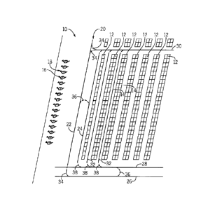
supplemented with a
Warehouse Management System (WMS) to provide guidance and instructions to the
autonomous
vehicle.
[0004] In some applications, wire guidance navigation systems are used to
direct the
autonomous vehicles. The autonomous vehicles use a wire embedded in a
warehouse floor to steer
the material handling vehicle. The wire includes a radio frequency signal that
is sensed by a truck
control system (TCS), which uses the signal to steer the truck precisely in
line with the wire.
[0005] Wire guidance navigation has proven reliable, but includes
limitations. The installation
of wires incurs a substantial cost. Notches must be cut into the floor to
accommodate a wire, and
then must be filled with epoxy. While this provides a robust installation, it
can be both expensive
and inflexible. Any necessary maintenance or modification to the installed
system can be time-
intensive and costly. Additional navigation equipment can be required to send
and receive data
from the WMS, which can cause signal interference amongst the various
electronic devices present
in a warehouse.
[0006] In addition to wire guidance systems built into the floor, almost
all WMS use some
kind of broadcast system to convey information to and from the truck.
Typically this is WiFi or
QB\56145811.1 - 1 -
CA 3034361 2019-02-20
Attorney Docket No. 780139.00961.RC822
broadcast of Radio Frequency (RF) that propagates in straight lines. This
method works only
because the broadcast signal bounces off surfaces and the information flow is
asynchronous, not
real time. That is, when a material handling vehicle happens to pass through
an area with good
broadcast RF, it will exchange some information with the WiFi broadcast
system. This is
acceptable for handling small amounts of asynchronous information flow; for
example truck
location to the WMS and directions to move a pallet from the WMS to the truck.
BRIEF SUMMARY
[0007] The present disclosure relates generally to wire guidance and remote
operation for
vehicles. Specifically, the present disclosure relates to systems and methods
for guiding and
operating material handling vehicles through a warehouse. In some aspects, a
wire guidance
system according to the present disclosure may be used with an autonomous or
semi-autonomous
vehicle. The wire guidance system can include optical guidance as well, and
can allow for two-
way communication between a material handling vehicle and a Warehouse
Management System.
[0008] In one aspect, the present disclosure provides a material handling
vehicle guidance
system. The material handling vehicle guidance system includes a first
conductive member and a
second conductive member electrically coupled to the first conductive member.
The second
conductive member extends parallel to the first conductive member to define a
loop. The first
conductive member and the second conductive members are coupled to a shielded
cable connector.
An electrical current source supplies current to the first conductive member
in a first direction and
supplies current to the second conductive member in a second direction
opposite the first direction.
The opposing currents produce a narrowcast frequency signal that is detectable
between the first
conductive member and the second conductive member.
[0009] In another aspect, the present disclosure provides a method of
controlling a material
handling vehicle in a warehouse. The method includes passing a current through
a loop formed of
a first conductive member and a second conductive member. The first conductive
member and
the second conductive member extend approximately parallel to one another to
supply current in
a first direction and a second direction substantially opposing the first
direction. Navigational data
is communicated to a material handling vehicle by transmitting a narrowcast
radio frequency from
the loop to an antenna coupled to the material handling vehicle.
QB\56145811.1 -2 -
CA 3034361 2019-02-20
Attorney Docket No. 780139.00961.RC822
[0010] In another aspect, the present disclosure provides a material
handling vehicle. The
material handling vehicle includes a body defining a frame that has a base. A
receiving and
transmitting antenna is coupled to the base, and extends downward from the
base. The antenna is
configured to detect a narrowcast radio frequency signal generated between a
first conductive
member and a second conductive member below the frame. An optical detector
coupled to the
base extends downward from the base as well. The optical detector and the
receiving and
transmitting antenna are electrically coupled to a truck control system. The
truck control system
is configured to adjust steering of the material handling vehicle based upon
data received from the
antenna and the optical detector.
[0011] The foregoing and other aspects and advantages of the disclosure
will appear from the
following description. In the description, reference is made to the
accompanying drawings which
form a part hereof, and in which there is shown by way of illustration a
preferred configuration of
the disclosure. Such configuration does not necessarily represent the full
scope of the disclosure,
however, and reference is made therefore to the claims and herein for
interpreting the scope of the
disclosure.
BRIEF DESCRIPTION OF DRAWINGS
[0012] The invention will be better understood and features, aspects and
advantages other than
those set forth above will become apparent when consideration is given to the
following detailed
description thereof. Such detailed description makes reference to the
following drawings.
[0013] FIG. 1 a plan view of a warehouse incorporating a wire guidance
system in accordance
with an aspect of the disclosure.
[0014] FIG. 2 is a schematic view of a communication system coupled to the
wire guidance
system of FIG. 1.
[0015] FIG. 3 is cross-sectional view of a warehouse floor having the wire
guidance system of
FIG. 1 installed therein, taken along cut line 3-3 in FIG. 1.
[0016] FIG. 4 is a schematic view of the electromagnetic fields produced by
current passing
through the wire guidance system of FIG. 1.
[0017] FIG. 5 is a bottom view of a material handling vehicle centered over
the wire guidance
system of FIG. 1.
- 3 -
QB\56145811.1
CA 3034361 2019-02-20
Attorney Docket No. 780139.00961.RC822
[0018] FIG. 6 is an exploded view of a warehouse floor and tape
incorporating a wire guidance
system in accordance with another aspect of the disclosure.
[0019] FIG. 7 is a top view of the wire guidance system of FIG. 6.
[0020] Corresponding reference characters indicate corresponding parts
throughout several
views. Although the drawings represent embodiments of the present disclosure,
the drawings are
not necessarily to scale and certain features may be exaggerated in order to
better illustrate and
explain the embodiments of the present disclosure.
DETAILED DESCRIPTION
[0021] The invention will now be described more specifically with reference
to the following
embodiments. It is to be noted that the following embodiments are presented
herein for purpose
of illustration and description only. It is not intended to be exhaustive or
to be limited to the precise
form disclosed.
[0022] It is to be understood that the phraseology and terminology used
herein is for the
purpose of description and should not be regarded as limiting. The use of
"including,"
"comprising," or "having" and variations thereof herein is meant to encompass
the items listed
thereafter and equivalents thereof as well as additional items.
[0023] Generally, the present disclosure provides systems and methods for
remotely
controlling and operating material handling vehicles. While the systems and
methods for remotely
controlling and operating vehicles are discussed only with respect to material
handling vehicles, it
should be appreciated that the various aspects of the disclosure can be
applied to other vehicles as
well.
[0024] Fig. 1 illustrates one non-limiting example of a warehouse 10
according to the present
disclosure. The warehouse 10 includes several racks 12 spaced apart from one
another that extend
through the warehouse 10 to define aisles 14. The racks 12 may store pallets
(not shown) or other
items that can be retrieved or moved by one or more material handling vehicles
16 present within
a fleet 18.
[0025] A network of wire loops 20 extends throughout the warehouse 10 to
provide wire
guidance to one or more material handling vehicles 16 that operate within the
warehouse 10. The
network of wire loops 20 provide an electrical signal to the material handling
vehicles 16, which
helps maintain the vehicles 16 centered over the wire loops 20 during
operation. The network of
- 4 -
QB\56145811.1
CA 3034361 2019-02-20
Attorney Docket No. 780139.00961.RC822
wire loops 20 can be placed in electrical communication with a Warehouse
Management System
(WMS), which can provide signals to the wire loops 20 to direct the material
handling vehicles 16
through the warehouse 10.
[0026] The network of wire loops 20 can be arranged to allow rapid and
precise movement of
material handling vehicles 16 throughout the entire warehouse 10. An outer
perimeter can be
partially established by a first wire loop 22, a second wire loop 24 extending
approximately parallel
to the first wire loop 22, a third wire loop 26 extending perpendicularly to
the first wire loop 22,
and a fourth wire loop 28 extending approximately parallel to the third wire
loop 26. In some
aspects, the first wire loop 22, second wire loop 24, third wire loop 26, and
fourth wire loop 28 are
positioned outward from the racks 12, and form a primary material handling
vehicle path
throughout the warehouse 10.
[0027] A crossing loop 30 can extend away from the outer perimeter of the
network 20 (e.g.,
from the first loop 22), which can extend perpendicularly to the racks 12 and
aisles 14. In some
aspects, the crossing loop 30 can be used to navigate the material handling
vehicle 16 through the
warehouse until it reaches a desired aisle loop 32. In some aspects, each
aisle 14 includes an aisle
loop 32 extending approximately parallel to the racks 12 that define the aisle
14. The aisle loop
32 can extend through a portion of the aisle 14 to guide a material handling
vehicle 16 within the
aisle 14. For example, the aisle loop 32 can extend the entire length of the
aisle 14.
[0028] Optical guidance can be provided with each wire loop in the network
20. For example,
each wire loop in the network 20 can be painted over with a visible stripe.
The visible stripe can
be detected by an optical detector (e.g., the optical detector 74, shown in
FIG. 5) present on the
material handling vehicle 16. The visible stripe may have a color or pattern
that indicates which
aisle of the warehouse 10 the wire loop is located. The optical detector can
be a digital camera or
light sensor with an integrated light source oriented at the floor to sense
the visible stripe. The
visible stripe can be simply painted on the floor or it can be a tape attached
to the floor. In some
aspects, the paint or tape can be applied on top of a wire loop tape can
contain a wire loop. In some
aspects, a wire loop can be arranged on an adhesive side of the tape or
embedded within the tape
before the tape is applied to the floor.
[0029] In addition to the visible stripes present above each wire loop in
the network 20,
transitional stripes 34, 36, 38 can extend between the wire loops 22, 24, 26,
28, 30, 32 in the
network 20. In some aspects, a gap exists between each wire loop in the
network 20. When a
QB\56145811.1 -5 -
CA 3034361 2019-02-20
Attorney Docket No. 780139.00961.RC822
material handling vehicle 16 is given a task (e.g., a WMS assigns the material
handling vehicle 16
to retrieve an item from a specific location on a rack 12), the material
handling vehicle 16 may
need to traverse several wire loops 22, 24, 26, 28, 30, 32 within the
warehouse 10 to arrive at the
specific location on the rack 12. Transitional stripes 34, 36, 38 can provide
optical indication
and/or guidance to a material handling vehicle 16 as it transitions from one
wire loop (e.g., the
first wire loop 22) to another wire loop (e.g., the third loop 26). As the
material handling vehicle
16 approaches the transitional stripe 34, 36, 38, it can optically detect the
path it should take to
transition from being guided by one wire loop to the next wire loop.
[0030] The transitional stripes 34, 36, 38 can be provided in several
locations throughout the
network 20. For example, transitional stripes 34 can be provided between each
wire loop 22, 24,
26, 28 in the outer perimeter of the network 20. The transitional stripes 34
may form a smoothly
curving arc that extends about 90 degrees to tangentially direct a material
handling vehicle 16 from
one wire loop to another wire loop. Transitional stripes 36 can also extend
between the wire loops
22, 24, 26, 28 to optically guide a material handling vehicle 16 through a U-
turn. A 180 degree
arc can extend between two parallel loops (e.g., the first and second wire
loops 22, 24, or the third
and fourth wire loops 26, 28) to guide a material handling vehicle 16 as it
reverses direction onto
an adjacent wire loop. Transitional stripes 38 can also extend away from the
aisle loops 32 toward
the outer perimeter loops 22, 24, 26, 28 and the crossing loop 30. The
transitional stripes 38 can
be defined by a smoothly curving arc extending approximately 90 degrees
between each loop.
[0031] FIGS. 2-5 illustrate the wire loop construction and function. Each
wire loop, such as
the first wire loop 22 shown in FIG. 2, is constructed of two conductive
members 40, 42, which
are electrically coupled to one another to define a loop. Each of the
conductive members 40, 42
extend away from a shielded cable connector 44. The first conductive member 40
and the second
conductive member 42 can extend away from the shielded cable connector 44 in a
substantially
parallel manner. In some aspects, the first conductive member 40 and the
second conductive
member 42 are each placed into notches 45, 46 formed or cut in the warehouse
floor 48. Epoxy
can be filled in around the conductive members 40, 42 to secure them within
the notches 45, 46 in
the floor 48. In some aspects, a single notch (not shown) can accommodate both
conductive
members 40, 42, which may reduce installation costs. The conductive members
40, 42 can be
constructed from metal wires, metal foil, and/or conductive paint where
appropriate. The
conductive paint can include an epoxy with metal particles.
QB\56145811.1 - 6 -
CA 3034361 2019-02-20
Attorney Docket No. 780139.00961.RC822
[0032] The first conductive member 40 and the second conductive member 42
can be spaced
apart from one another by a distance D. In some aspects, the distance D can
range between about
.05 cm (.02 inches) and about 10.2 cm (4.0 inches). The distance D can be
chosen based upon the
desired communication frequency used in the warehouse 10. In some aspects, the
distance D can
be selected to be about four times larger than the wavelength of the
communication frequency used
in the warehouse 10, which may help transmit and receive signals at the
communication frequency.
For example, a warehouse 10 operating on a 23.6 GHz frequency may use
conductive members
40, 42 spaced apart by a distance D of about 5.1 cm (2.0 inches). A variety of
high frequencies
can be used to communicate signals through the conductive members 40, 42. For
example,
frequencies between about 1 GHz to greater than 200 GHz can be transmitted
through and received
by the conductive members 40, 42. Standard frequencies such as 2.4 GHz, 3.6
GHz, 5 GHz, or 60
GHz may also be used.
[0033] When electrical current is supplied to the wire loop 22, the current
travels along the
first conductive member 40 in a first direction away from the shielded cable
connector 44, passes
to the second conductive member 42, and returns toward the shielded cable
connector 44 along the
second conductive member 42 in a second direction substantially opposite of
the first direction.
The opposing currents produce electromagnetic fields 50, 52, which emanate
outwardly from the
conductive members 40, 42 at the current frequency to produce a near field
signal.
[0034] Because the currents passing through the first conductive member 40
and the second
conductive member 42 oppose one another, the electromagnetic fields 50, 52
produced by the
currents can extend in opposite directions. As shown in FIG. 4, for example,
the current flowing
through the first conductive member 40 can produce an electromagnetic field 50
extending
counterclockwise about the first conductive member 40, while the second
conductive member 42
can produce an electromagnetic field 52 extending clockwise about the second
conductive member
42.
100351 The positioning of the conductive members 40, 42 relative to one
another produces a
narrowcasting signal, which may only be detectable in an area 54 between and
above the two
conductive members 40, 42, where it is strongest. As shown in FIG. 4, the
electromagnetic fields
50, 52 extend in opposing directions. Although the electromagnetic fields 50,
52 produced by the
first conductive member 40 and the second conductive member 42 oppose one
another, the
electromagnetic fields 50, 52 are additive in the area 54 directly between and
above the two
QB\56145811.1 - 7 -
CA 3034361 2019-02-20
Attorney Docket No. 780139.00961.RC822
conductive members 40, 42. Because both fields 50, 52 extend in a similar
direction in the additive
area 54, they can produce a strong radio frequency signal that can be detected
or received by an
antenna or other receiving device present above and between the two conductive
members 40, 42.
The radio frequency signal is strongest along the centerline 56 between the
two conductive
members 40, 42.
[0036] Outside of the additive area 54, the electromagnetic fields 50, 52
oppose one another,
which includes a canceling effect on any resultant radio frequency signal
produced by the current
passing through the conductive members 40, 42. The resultant radio frequency
signal becomes
weaker further away from the conductive members 40, 42, and may be
undetectable in these areas.
The resultant electromagnetic field 58 demonstrates the canceling effect of
the electromagnetic
fields 50, 52, which occurs outside the area 54 between the conductive members
40, 42. The first
wire loop 22 (and other loops 24, 26, 28, 30, 32 within the network 20)
functions as a narrowcasting
network, where a strong signal can be detected only within a confined area
(i.e., the area 54
between and above the conductive members 40, 42), rather than a broadcasting
network, where
radio frequency power is distributed throughout a larger area. The canceling
effect of the resultant
electromagnetic field 58 can reduce the amount of interference introduced into
other
communication systems used within the warehouse 10, such as cellular or WiFi.
The metal racks
12 in the warehouse 10 can also reduce the amount of interference produced by
the resultant
electromagnetic fields 58 produced by the wire loops in the network 20.
[0037] The current and/or resulting radio frequency signal can be supplied
to the conductive
members 40, 42 from an outside source, such as a Warehouse Management System
(WMS). The
shielded cable connector 44 can be coupled to a local WiFi node 60 (see FIG.
2). The local WiFi
node 60 can be a WiFi unit 62 based on the IEEE 802.11 standards, and can use
the wire loop (e.g.,
first wire loop 22) as its antenna. The local WiFi node 60 can be a node on
the warehouse Ethernet
64, which can receive data from a network hub computer (not shown). When the
local WiFi node
60 receives a signal from the network hub computer or WMS, the local WiFi node
60 may
demodulate the signal to extract information from the received signal.
Depending upon the type
of signal received, the local WiFi node 60 can transmit a high frequency radio
frequency signal
through the shielded cable connector 44 and onto the first and second
conductive members 40, 42,
which may transmit the signal upward, where it can be detected by a material
handling vehicle 16.
In some aspects, the local WiFi node 60 contains a superheterodyne receiver to
receive an
QB\56145811.1 - 8 -
CA 3034361 2019-02-20
=
Attorney Docket No. 780139.00961.RC822
incoming signal from the WMS and convert the received signal into a frequency
that can then be
passed onto the conductive members 40, 42 of the wire loop.
[0038] The radio frequency signal carried by the conductive members 40, 42
can be received
by an antenna 66 coupled to the material handling vehicle 16, as shown in FIG.
5. In some aspects,
the antenna 66 is coupled to a base 70 of a steel frame 68 that can partially
define the material
handling vehicle 16. The antenna 66 can be positioned between each of the
wheels 72,
approximately centered on the base 70 of the steel frame 68. In some aspects,
the antenna 66 is
electrically coupled to a Truck Control System (TCS) (not shown), which can
demodulate the radio
frequency signal detected by the antenna 66 and use the information contained
within the signal to
execute various material handling vehicle 16 functions. The TCS can include a
Vehicle Manager
(VM) that uses a micro-controller in communication with multiple field-
programmable gate array
(FPGA) logic chips to communicate with and control various subsystems (e.g.,
the steering motor,
lift pump, traction motor, etc.) on the material handling vehicle 16 through a
digital bus. The TCS
can also include relays, display modules, badge readers, RFID chip readers,
proximity sensors,
and other electronic systems present within the material handling vehicle 16,
such that
communication with the TCS can allow the material handling vehicle 16 to be
externally
controlled. For example, the radio frequency signal carried by the conductive
members 40, 42
may contain navigation instructions, which can be received and processed by
the TCS. The VM
within the TCS can then navigate the material handling vehicle 16 according to
the navigation
instructions received by the TCS, and can move the material handling vehicle
16 throughout the
warehouse 10. In some aspects, the radio frequency signal can include remote
controlling
instructions provided by an operator, who could then operate the material
handling vehicle 16
using a computer (e.g., a personal laptop) connected to the warehouse Ethernet
64. This may allow
an operator to semi-autonomously operate a material handling vehicle 16 from a
location outside
the warehouse 10 entirely.
[0039] In addition to receiving information, the strength of the signal
detected by the antenna
66 can be used to help locate the material handling vehicle 16 above the wire
loop 22. As indicated
previously, the highest radio frequency signal is present directly between the
two conductive
members 40, 42, and the strength of the signal received by the antenna 66 is
directly correlated to
the antenna's 66 (and material handling vehicle's 16) position relative to the
two conductive
members 40, 42 (i.e., the signal may be strongest along the centerline 56 in
the narrowcasting area
QB\56145811.1 - 9 -
CA 3034361 2019-02-20
Attorney Docket No. 780139.00961.RC822
54). In some aspects, the TCS of the material handling vehicle 16 can be
programmed with a
threshold signal amplitude, which corresponds to the amplitude of a signal
that would be produced
if the material handling vehicle 16 is properly located above a wire loop
(e.g., the first wire loop
22). The TCS can continuously monitor the material handling vehicle's 16
position relative to the
loop by comparing the signal received by the antenna 66 to the threshold value
stored within the
TCS. If the value falls below the predetermined "acceptable" amplitude, the
TCS can adjust the
steering of the material handling vehicle 16 until a value above the amplitude
threshold is received
by the antenna 66. This can maintain the material handling vehicle 16 aligned
properly with the
wire loop. In other aspects, several antennae 66 can be used to detect the
lateral distance of the
material handling vehicle 16 relative to the loop, as discussed in U.S. Patent
No. 6,445,984, which
is hereby incorporated by reference in its entirety.
[0040] An optical detector 74 can be coupled to the base 70 of the steel
frame 68 to further
guide the material handling vehicle 16 throughout the warehouse. In some
aspects, the optical
detector 74 can be a light sensor with an integrated light source that
provides visible white light,
visible light of a specific color, or infrared light. The light sensor can
detect light reflected from
the visible stripe of one of the wire loops 22, 24, 26, 28, 30, 32 and/or one
of the transitional stripes
34, 36, 38. The light sensor can distinguish the color of the reflected light,
which may be used to
determine a location of the material handling vehicle 16 in the warehouse 10
and/or on one of the
wire loops 22, 24, 26, 28, 30, or 32. The color of the reflected light may
indicate if the optical
sensor 74 is positioned over visible bars 90 of Fig. 7. In other aspects, the
optical detector 74 can
be a camera that can detect a color or pattern. The camera can have an
integrated light source that
provides visible white light, visible light of a specific color, or infrared
light. The optical detector
can detect color from tape, paint, or concrete dye with or without a top
coating of protective epoxy,
allowing for colors and/or patterns to be marked in a variety of manners.
[0041] The optical detector 74 can be positioned in line with the antenna
66, and can
supplement, or completely replace, the wire guidance provided by the
conductive members 40, 42.
In some aspects, the optical detector 74 is positioned near a leading end 76
of the material handling
vehicle 16. For example, the optical detector 74 can be positioned near one or
more forks 78 that
extend forward of the steel frame 68 of the material handling vehicle 16. The
optical detector 74
can be used to optically detect the position the material handling vehicle 16
is in currently, as well
QB\56145811.1 - 10 -
CA 3034361 2019-02-20
Attorney Docket No. 780139.00961.RC822
as to identify obstacles, turns, or the end of an aisle 14 that may be in
front of the material handling
vehicle 16.
[0042] The optical detector 74 can help direct the material handling
vehicle 16 to stay properly
positioned above the wire loop. For example, if the antenna 66 detects that
the detected radio
frequency signal has fallen below the necessary amplitude threshold, the
optical detector 74 can
optically detect which direction the material handling vehicle 16 must steer
in order to be properly
aligned with the wire loop once more. The visible stripes present above the
loops in the network
20 provide easily detectable markers for the optical detector 74 to sense.
Data taken by the optical
detector 74 can be communicated to the TCS, which adjusts the steering of the
material handling
vehicle 16 as necessary.
[0043] The optical detector 74 can help the material handling vehicle 16
transition between
the different wire loops in the network 20 to reach a desired destination.
When the optical detector
74 detects that a transitional stripe 34, 36, 38 is approaching, the optical
detector 74 can alert the
TCS, which can temporarily disable wire guidance. Using the optical detector
74, the TCS can
smoothly steer the material handling vehicle 16 along the transitional stripes
34, 36, 38, until the
material handling vehicle 16 is once again centered over a wire loop within
the network 20. Once
the optical detector 74 detects that the material handling vehicle 16 is
positioned above a wire
loop, the TCS can reinitiate the wire guidance system.
[0044] In some aspects, a transmitter 80 can also be coupled to the
material handling vehicle
16. The transmitter 80, like the antenna 66, can be coupled to the base 70 of
the steel frame 68.
The transmitter 80 can be positioned between each of the wheels 66,
approximately centered on
the base 70 of the steel frame 68. The transmitter 80 can be placed in
electrical communication
with the TCS, and can be used to transmit information from the TCS to the wire
loop 22 positioned
below the material handing vehicle 16. The transmitter 80 may have one or more
coils configured
to transmit RF energy to induce currents at a predetermined frequency in the
conductive members
40, 42 and transmit a signal to the WiFi node 60. The signal may have a
frequency ranging from
1 GHz to 100 GHz. The underside of the material handling vehicle 16 can
prevent the RF energy
from spreading away from the conductive members 40, 42 and thus interfering
with components
of the warehouse 10. The opposing currents can carry a signal with information
about the material
handling vehicle 16 to the WiFi node 60. For example, the transmitter 80 could
transmit the
material handling vehicle's 16 position within the warehouse 10, based upon
readings from the
QB\56145811.1 - 11 -
CA 3034361 2019-02-20
Attorney Docket No. 780139.00961.RC822
optical detector 74 and the antenna 66. In some aspects, the transmitter 80
could communicate
with the wire loop 22 (which communicates with the WMS) that an assigned task
(e.g., retrieving
an item from a specific rack 12 within the warehouse 10) has been completed,
and that the material
handling vehicle 16 is ready to be assigned a new task. In still other
aspects, the material handling
vehicle 16 could use the transmitter 80 to notify the WMS that an unexpected
scenario has been
encountered, and the material handling vehicle 16 desires assistance from an
operator. In some
embodiments, the transmitter 80 and antenna 66 are electrically coupled to one
another. In some
embodiments, the transmitter 80 and antenna 66 may be a one or more receiving
and transmitting
antennas each performing at least a portion of the functions of the
transmitter 80 and antenna 66.
100451 If the material handling vehicle 16 transmits a radio frequency
signal to the conductive
members 40, 42 below, the radio frequency signal can be carried from the loop
to the shielded
cable connector 44, and to the local WiFi node 60. In some aspects, the local
WiFi node 60
includes a demodulator, which can extract the information from the radio
frequency signal
received from the material handling vehicle 16. The local WiFi node 60 may
then transmit a signal
through the WiFi unit 62 to the warehouse Ethernet 64, which may be coupled
with the WMS.
The WMS can receive the signal, demodulate it, and determine the appropriate
course of action to
respond to the information received from the material handling vehicle 16. For
example, the WMS
can assign a new task to the material handling vehicle 16 by sending a signal
through the local
WiFi node 60, through the shielded cable connector 44, and onto the conductive
members 40, 42,
where it can be detected by the material handling vehicle 16. In some aspects,
the antenna 66 and
transmitter 80 operate on different channels, so that two-way communication
through the
conductive members 40, 42 and the material handling vehicle 16 can occur
simultaneously. Both
the signal transmitted from the material handling vehicle 16 and the signal
transmitted to the
material handling vehicle 16 may be present in the conductive members 40, 42.
The demodulator
may be able to separate the signal transmitted from the material handling
vehicle 16 and the signal
transmitted to the material handling vehicle 16 in order to implement two-way
communication.
For example, the demodulator may receive a single combined current via the
shielded cable
connector 44 with both the signal transmitted from the transmitter 80 to the
WiFi node 60 and the
signal transmitted from the WiFi node 60 to the antenna 66. The demodulator
can then filter out
a signal corresponding to the carrier frequency of the channel the transmitter
80 is operating on
and then process the information transmitted from the material handling
vehicle 16. In other
QB\56145811.1 - 12 -
CA 3034361 2019-02-20
Attorney Docket No. 780139.00961.RC822
aspects, the transmitter 80 and the antenna 66 may operate on the same channel
while still allowing
two-way communication to occur. For example, the WiFi node 60 can use an
appropriate
technique such as a full-duplex or simultaneous transmission and reception
(STR) technique to
detect appropriate signals and implement two-way communication.
[0046] High speed two-way communication between the material handling
vehicle 16 and the
WMS can enable the autonomous material handling vehicle 16 to be selectively
controlled by an
operator, who may be present remotely from the material handling vehicle 16.
For example, when
the material handling vehicle's 16 autonomous control system (e.g., the TCS)
detects an obstacle
that affects its navigation, it may transmit a signal along the network 20
that it requests assistance.
An operator positioned at a computer in communication with the network 20 can
accept the
assistance request, which can then provide remote control of the material
handling vehicle 16.
Conductive members 40, 42 of the loop can be used with the antenna 66 and
transmitter 80 to send
and receive high frequency signals between the computer and the material
handling vehicle 16 to
enable the operator to communicate with and control the material handling
vehicle 16. The
computer can display a live video feed being taken from one or more video
cameras 75 on the
material handling vehicle 16, which can supply the operator with a field of
view in front of the
material handling vehicle 16. The video cameras 75 can be positioned around
the material
handling vehicle 16 to provide views that might be difficult or even
impossible to see by an
operator seated within the material handling vehicle 16. For example, video
cameras 75 can be
directed toward the forks 78, which can allow an operator to align the forks
78 with a pallet,
regardless of the pallet's height relative to the material handling vehicle
16. Using the optical
footage, the operator can then control the material handling vehicle 16 and
navigate it through the
scenario that originally created the request for assistance. Once the material
handling vehicle 16
includes been successfully maneuvered by the remote operator, control can be
returned to the TCS
of the material handling vehicle 16, and autonomous operation can resume.
Using a central
computer with the network 20, multiple material handling vehicles 16 can be
selectively controlled
by a single remote operator, which can reduce labor costs.
[0047] In some aspects, additional antennae (not shown) may be coupled to
the material
handling vehicle 16 to receive or communicate information throughout the
warehouse 10. For
example, WiFi units 62 may broadcast vehicle instructions throughout the
warehouse, which can
be received and processed by the TCS of the material handling vehicle 16. The
broadcast WiFi
QB\56145811.1 - 13 -
CA 3034361 2019-02-20
Attorney Docket No. 780139.00961.RC822
can also be used to determine the material handling vehicle's 16 position
along a wire guidance
loop (e.g., wire loops 22, 24, 26, 28, 30, 32). In some aspects, the same
instructions can be
transmitted to a material handling vehicle 16 through both broadcast WiFi and
the loop network
20. The time delay between receiving a broadcast radio signal and receiving
the same signal
through a wire loop can be measured, and the calculated time delay between
receiving the signals
can determine the location of the material handling vehicle 16 relative to the
wire loop. In some
aspects, time delay measurement can be used to supplement or replace the
optical detector 74 to
direct the material handling vehicle 16 throughout the warehouse 10.
100481 FIGS. 6 and 7 show another aspect of a wire loop 82 that can be
incorporated into the
warehouse network 20. Instead of creating notches (e.g., notches 45, 46, shown
in FIG. 3) in the
warehouse floor 48, first and second conductive members 40', 42' in the form
of metal foil
conductors can be adhesively coupled to the warehouse floor 48. The wire loop
82 can be a tape
having multiple layers 84, 86, 88 that secure the wire loop 82 to the
warehouse floor 48 while also
protecting the metal foil of the first and second conductive members 40', 42'.
The conductive
members 40', 42' are electrically coupled to one another to form a wire loop
82. Similar to the first
and second conductive members 40, 42, the first and second conductive members
40', 42' are
spaced apart by the distance D. Like the first wire loop 22 shown in FIG. 2,
the wire loop 82 can
be electrically coupled to a shielded cable connector 44, as well as a local
WiFi node 60, WiFi unit
62, warehouse Ethernet 64, and a WMS.
100491 A top layer 84 can include a visible stripe that can be readily
detected by the optical
detector 74 of the material handling vehicle 16. In some aspects, the top
layer 84 also includes
visible bars 90 spaced apart about the top layer 84. The visible bars 90 can
extend across the top
layer 84 to indicate distance on the wire loop 82. As a material handling
vehicle 16 travels over
the wire loop 82, the optical detector 74 can optically detect the visible
bars 90, which can indicate
the position of the material handling vehicle 16 relative to the wire loop 82.
For example, the
visible bars 90 can be spaced apart from one another every 0.6 meters (2
feet), and can be about
0.01 m (0.5 in) thick. The optical detector 74 can be used to count the number
of bars traversed,
which can be communicated to the wire loop 82, which can then be transmitted
to the WMS. In
other aspects, the visible bars 90 can be given different colors, which can
correspond to different
distances along the wire loop 82. If the material handling vehicle 16 is
between two visible bars
90, the position of the material handling vehicle 16 on the wire loop 82 can
be calculated using the
QB\56145811.1 - 14 -
CA 3034361 2019-02-20
Attorney Docket No. 780139.00961.RC822
number of rotations of the material handling vehicle's 16 wheels 72 or by
using the time delay
measurement technique discussed previously. Data can be broadcasted over the
warehouse WiFi
and through the wire loop 82, and the amount of time it takes for the antenna
66 of the material
handling vehicle 16 to receive the data can be used to calculate the position
of the material handling
vehicle 16 on the wire loop 82.
[0050] Using aspects of the disclosure, remote operation of a material
handling vehicle can be
accomplished. The network of loops provides reliable two-way communication
with material
handling vehicles, which can transmit and receive information between the TCS
and the WMS to
effectively accomplish tasks within a warehouse automatically. Remote
operators can be notified
when material handling vehicles encounter a scenario outside of their working
set of instructions,
and can temporarily take over the operation of a material handling vehicle
until the unforeseen
scenario includes been resolved. Using the systems and methods disclosed
herein, one remote
operator may manage one or more material handling vehicles, which can reduce
labor costs.
[0051] Within this specification embodiments have been described in a way
which enables a
clear and concise specification to be written, but it is intended and will be
appreciated that
embodiments may be variously combined or separated without parting from the
invention. For
example, it will be appreciated that all preferred features described herein
are applicable to all
aspects of the invention described herein.
[00521 Thus, while the invention includes been described in connection with
particular
embodiments and examples, the invention is not necessarily so limited, and
that numerous other
embodiments, examples, uses, modifications and departures from the
embodiments, examples and
uses are intended to be encompassed by the claims attached hereto. The entire
disclosure of each
patent and publication cited herein is incorporated by reference, as if each
such patent or
publication were individually incorporated by reference herein.
[0053] Various features and advantages of the invention are set forth in
the following claims.
QB\56145811.1 - 15 -
CA 3034361 2019-02-20