Note: Descriptions are shown in the official language in which they were submitted.
CA 03034477 2019-02-20
WO 2018/049297
PCT/US2017/050890
TITLE: PROTECTIVE GLOVES AND METHOD OF MAKING PROTECT WE
GLOVES
BACKGROUND OF THE INVENTION
1. Field of the Invention
This invention relates generally to protective guards, and specific
embodiments relate to
protective guards that inhibit skin penetration by sharps.
2. Description of Related Art
Medical practitioners including, but not limited to, doctors, physician
assistants, nurses,
dentists, and dental assistants may use instruments, implants, and/or needles
during medical
procedures. Medical procedures may include, but are not limited to, surgical
procedures and
operations, dental procedures and operations, and injection or drawing of
fluids using needles. A
risk exists that a medical practitioner's skin may be punctured or penetrated
during a medical
procedure, resulting in a percutaneous injury. A medical practitioner's skin
may also be
punctured or penetrated during disposal or cleaning of needles or medical
instruments previously
used in a medical procedure. The medical practitioner and/or patient may be
subject to infection
or disease including, but not limited to, staphylococcus, hepatitis, and
acquired
immunodeficiency syndrome (AIDS) due to an inadvertent skin puncture of the
medical
practitioner. With or without transmission of a disease or pathogen, a skin
puncture or other
wound may be traumatic to the medical practitioner. There is a need to protect
medical
practitioners and patients from the risk of infection and pathogens due to
skin punctures or
wounds of the medical practitioner during a medical procedure.
Surgical gloves may be used by medical practitioners to lessen the risk of
transferring
blood-borne and other pathogens during medical procedures. Surgical gloves,
however, typically
do not provide adequate protection from penetration of skin by sharps. Sharps
may include, but
are not limited to, hypodermic needles; medical, dental and laboratory
instruments (such as
scalpels); and burs and sharp edges or projections of hard tissue and
prostheses. Studies show
that puncture wounds of medical practitioners often occur on backs of a
medical practitioner's
fingers or thumb. Puncture wounds may occur predominantly to the index finger,
thumb, and
middle finger. For example, a medical practitioner may hold a syringe in a
dominant hand while
1
CA 03034477 2019-02-20
WO 2018/049297
PCT/US2017/050890
stabilizing, retracting, isolating, or palpating tissue with the other hand. A
sudden movement by
the patient may cause the medical practitioner to accidentally puncture the
back of a finger or
thumb of the non-dominant hand.
Cut and/or puncture resistant gloves are useful in other industries.
Protective gloves are
used in the food service industry, wherein the glove is intended to act as a
protective barrier for
food contact. However, many food preparation workers also could benefit from
having a glove
that protects the worker's hands from cutting utensils. In cosmetology
application, barbers and
hair salons use gloves to protect the worker's hands from various chemicals
such as dyes and
bleaches used to color hair. Many cosmetologist could also benefit from a
glove that offers
protection from accidental scissor cuts and hair splinters. Finally, a cut
resistant glove would be
useful as a garden glove, a mechanics glove, sportsman's glove, an all-purpose
glove, and a
kitchen glove. While there are existing cut/puncture resistant gloves in many
of these industries,
such gloves tend to be bulky, making it difficult for the user to work.
U.S. Patent No. 5,450,626 issued to Sorrels, which is incorporated by
reference as if fully
set forth herein, discloses protective finger coverings that have flexible and
puncture resistant
construction. A finger covering may include a puncture resistant, protective
surface on a top side
of the covering, which fits over a dorsal portion of the finger. As used
herein, dorsal in relation
to a finger means that portion of the finger opposite the palm of the hand,
and ventral means that
portion of the finger adjacent the palm of the hand when a fist is formed. The
finger guide may
also include a retentive or elastic layer that may function to hold the
covering on a user's finger
or thumb. The retentive layer may be located on a bottom of the covering,
which fits over a
ventral portion of the finger. The covering may be open-ended to allow a
portion of a user's
thumb or finger to extend through the covering. The portion of the user's
thumb or finger that
extends through the covering may allow the user to retain tactile sense while
using the covering.
The covering may be rotated during use to change the position of the
protective surface.
Finger coverings and/or hand protectors may limit finger and/or hand
flexibility of the
user. Finger coverings and/or hand protectors may limit a user's sense of
touch during a
procedure. A user's sense of touch may be important during a medical
procedure, especially if
palpation of various surfaces of a treatment area is required during the
procedure. A medical
practitioner may need to retain a tactile sense during a medical procedure to
control a patient and
to maintain awareness of locations of sharp portions of instruments, inserts,
and/or needles.
2
CA 03034477 2019-02-20
WO 2018/049297
PCT/US2017/050890
Additionally, the use of finger and/or hand protectors may be limited by the
amount of working
space available within the patient. For example, a dentist does not have a
large amount of
working space within a patient's mouth. Also, a doctor typically does not have
a large amount of
working space within a patient during an invasive medical procedure.
SUMMARY OF THE INVENTION
In an embodiment, a protective glove for a hand, includes: a first
thermoplastic layer; and
a second thermoplastic layer heat welded to the first thermoplastic layer,
wherein the second
thermoplastic layer has a thickness greater than the thickness of the first
thermoplastic layer.
In some embodiments, the first thermoplastic layer covers the palm of a user's
hand
during use and the second thermoplastic layer covers the back of the user's
hand. In other
embodiments, the first thermoplastic layer covers the back of a user's hand
during use and the
second thermoplastic layer covers the palm of the user's hand.
In an embodiment, the second thermoplastic layer has a thickness that is about
twice the
thickness of the first thermoplastic layer. The first thermoplastic layer may
have a thickness of
about between about 0.02 mm to about 1.0 mm or between about 0.1 mm to about
0.5 mm. The
thickness of the second thermoplastic layer has a thickness that is greater
than the thickness of
the first thermoplastic layer and is in the range between about 0.1 mm to
about 1.0 mm or
between about 0.25 mm to about 0.75 mm.
In an embodiment, the first thermoplastic layer may have a durometer of about
20A to
about 100A and the second thermoplastic layer may have a durometer of about
70A to about
100Aor about 20D to about 50D. The second thermoplastic layer may be composed
of two or
more films heat welded together.
In an embodiment, the second thermoplastic layer may have a density that is
greater than
1 g/cm3.
In some embodiments, first thermoplastic layer and/or the second thermoplastic
layer
comprises polyethylene or polyurethane. The first thermoplastic material
and/or the second
thermoplastic material may be formed from a material that is resistant to
bodily fluids.
In an embodiment, the first thermoplastic material and/or the second
thermoplastic
material includes one or more folds which allow the first thermoplastic
material and/or the
second thermoplastic material to be bent without deformation of the first
thermoplastic material
and/or the second thermoplastic material.
3
CA 03034477 2019-02-20
WO 2018/049297
PCT/US2017/050890
In an embodiment, a guard for a digit of a hand, includes: a first
thermoplastic layer; and
a second thermoplastic layer welded to the first thermoplastic layer, wherein
the second
thermoplastic layer has a thickness greater than the thickness of the first
thermoplastic layer.
In an embodiment, a method of making a protective glove, includes: placing a
first
thermoplastic film in contact with a second thermoplastic film, wherein the
second thermoplastic
layer has a thickness greater than the thickness of the first thermoplastic
layer; heat welding the
first thermoplastic film to the second thermoplastic film by placing a heated
hand-shaped object
in contact with the first thermoplastic film and/or the second thermoplastic
film; and cutting the
glove from the heat welded films.
In an embodiment, the hand-shaped object comprises a cutting edge which cuts
the glove
from the heat welded films when the hand shaped object is placed in contact
with the first
thermoplastic film and/or the second thermoplastic film. The hand-shaped
object may be a
planar object. During the process of making the glove, the hand-shaped object
may be heated to
a temperature above the glass transition temperature of the first
thermoplastic film and/or the
.. second thermoplastic film.
In an embodiment, a protective glove for a hand, includes: a first
thermoplastic layer; and
a second thermoplastic layer welded to the first thermoplastic layer, wherein
the second
thermoplastic layer has a durometer greater than the durometer of the first
thermoplastic layer.
In some embodiments, the first thermoplastic layer covers the palm of a user's
hand
during use and the second thermoplastic layer covers the back of the user's
hand. In other
embodiments, the first thermoplastic layer covers the back of a user's hand
during use and the
second thermoplastic layer covers the palm of the user's hand.
The first thermoplastic layer may have a durometer of about 20A to about 40A
and the
second thermoplastic layer may have a durometer of about 70A to about 120A.
The second
thermoplastic layer may be composed of two or more films heat welded together.
In some embodiments, first thermoplastic layer and/or the second thermoplastic
layer
comprises polyethylene or polyurethane. The first thermoplastic material
and/or the second
thermoplastic material may be formed from a material that is resistant to
bodily fluids.
In an embodiment, the first thermoplastic material and/or the second
thermoplastic
material includes one or more folds which allow the first thermoplastic
material and/or the
4
CA 03034477 2019-02-20
WO 2018/049297
PCT/US2017/050890
second thermoplastic material to be bent without deformation of the first
thermoplastic material
and/or the second thermoplastic material.
In an embodiment, a guard for a digit of a hand, includes: a first
thermoplastic layer; and
a second thermoplastic layer welded to the first thermoplastic layer, wherein
the second
thermoplastic layer has a durometer greater than the durometer of the first
thermoplastic layer.
In an embodiment a method of making a protective glove, includes: placing a
first
thermoplastic film in contact with a second thermoplastic film, wherein the
second thermoplastic
layer has a durometer greater than the durometer of the first thermoplastic
layer; heat welding the
first thermoplastic film to the second thermoplastic film by placing a heated
hand-shaped object
in contact with the first thermoplastic film and/or the second thermoplastic
film; and cutting the
glove from the heat welded films.
In an embodiment, the hand-shaped object comprises a cutting edge which cuts
the glove
from the heat welded films when the hand shaped object is placed in contact
with the first
thermoplastic film and/or the second thermoplastic film. The hand-shaped
object may be a
planar object. During the process of making the glove, the hand-shaped object
may be heated to
a temperature above the glass transition temperature of the first
thermoplastic film and/or the
second thermoplastic film.
BRIEF DESCRIPTION OF THE DRAWINGS
Advantages of the present invention will become apparent to those skilled in
the art with
the benefit of the following detailed description of embodiments and upon
reference to the
accompanying drawings in which:
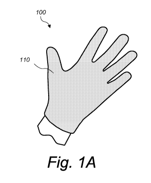
FIG. 1A depicts a puncture and/or cut resistant glove covering the back of a
user's hand;
FIG. 1B depicts a puncture and/or cut resistant glove covering the palm of a
user's hand;
FIG. 2A depicts a schematic diagram of a heat welding apparatus; and
FIG. 2B depicts a schematic diagram of a cutting and heat welding die.
While the invention may be susceptible to various modifications and
alternative forms,
specific embodiments thereof are shown by way of example in the drawings and
will herein be
described in detail. The drawings may not be to scale. It should be
understood, however, that
the drawings and detailed description thereto are not intended to limit the
invention to the
particular form disclosed, but to the contrary, the intention is to cover all
modifications,
5
CA 03034477 2019-02-20
WO 2018/049297
PCT/US2017/050890
equivalents, and alternatives falling within the spirit and scope of the
present invention as
defined by the appended claims.
DETAILED DESCRIPTION OF THE INVENTION
A protective guard may include a flexible and penetration resistant
construction to inhibit
injury to a user's hands and/or fingers. As used herein the term "protective
guard" refers to a
protective glove, for the hand of a user, or a protective device for one or
more digits of a hand.
A digit, as used herein, may be a finger or a thumb. The protective guard may
inhibit punctures
or wounds caused by needles, knives, or other sharp instruments. For example,
during the
utilization of a mechanically engineered syringe, there is window of time
before insertion and
after withdrawal during which the needle tip is exposed. During this time, the
protective guard
may inhibit a medical practitioner from receiving an injury to a finger or
thumb of the dominant
or non-dominant hand while retracting, isolating, or stabilizing the needle
tip.
In an embodiment, a protective glove for a hand includes: a first
thermoplastic layer; and
a second thermoplastic layer heat welded to the first thermoplastic layer,
wherein the second
thermoplastic layer has a thickness greater than the thickness of the first
thermoplastic layer. In
another embodiment, a protective guard for a digit of a hand includes: a first
thermoplastic layer;
and a second thermoplastic layer heat welded to the first thermoplastic layer,
wherein the second
thermoplastic layer has a thickness greater than the thickness of the first
thermoplastic layer.
In an embodiment, a protective glove for a hand includes: a first
thermoplastic layer; and
a second thermoplastic layer heat welded to the first thermoplastic layer,
wherein the second
thermoplastic layer has a durometer greater than the durometer of the first
thermoplastic layer.
In another embodiment, a protective guard for a digit of a hand includes: a
first thermoplastic
layer; and a second thermoplastic layer heat welded to the first thermoplastic
layer, wherein the
second thermoplastic layer has a durometer greater than the durometer of the
first thermoplastic
layer.
In an embodiment, the first thermoplastic layer covers the palm of a user's
hand during
use, and the second thermoplastic layer covers the back of the user's hand.
The second
thermoplastic layer provides a penetration and puncture resistant material to
the back of the
user's hand. In such an embodiment, the second thermoplastic layer may also
provide protection
to the dorsal portion of the user's fingers. As used herein, dorsal, in
relation to a finger, refers to
6
CA 03034477 2019-02-20
WO 2018/049297
PCT/US2017/050890
the portion of the finger opposite the palm of the hand. As used herein,
ventral, in relation to a
finger refers to the portion of the finger adjacent the palm of the hand when
a fist is formed.
In an alternate embodiment, the second thermoplastic layer covers the palm of
a user's
hand during use, and the first thermoplastic layer covers the back of the
user's hand. The second
thermoplastic layer provides a penetration and puncture resistant material to
the user's palm. In
such an embodiment, the second thermoplastic layer may also provide protection
to the ventral
portion of the user's fingers.
The protective properties of the second thermoplastic layer are obtained by
the increased
thickness of the second thermoplastic layer with respect to the first
thermoplastic layer. In some
embodiments, the second thermoplastic layer has a thickness that is about
twice the thickness of
the first thermoplastic layer. In an embodiment, the first thermoplastic layer
has a thickness of
about between about 0.02 mm to about 1.0 mm, and wherein the thickness of the
second
thermoplastic layer is between about 0,1 mm to about 1.0 mm. In preferred
embodiments, the
first thermoplastic layer has a thickness of about between about 0.1 mm to
about 0.5 mm, and
wherein the thickness of the second thermoplastic layer is between about 0.25
mm to about 0.75
mm.
Alternatively, the first and second thermoplastic layers can be characterized
by durometer
measurements. In one embodiment, the first thermoplastic layer has a durometer
of about 20A to
about 100A, and the second thermoplastic layer has a durometer of about 70A to
about 100A or
about 20D to about 50D.
The first thermoplastic layer and the second thermoplastic layer may be formed
from the
same thermoplastic material or different thermoplastic materials. In one
embodiment, the first
thermoplastic layer and/or the second thermoplastic layer are made from a
polyethylene polymer.
Exemplary polyethylene that may be used for forming a protective guard for the
hand include,
.. but are not limited to: medium-density polyethylene (MDPE) having a density
range of 0.926-
0.940 g/cm3; linear low-density polyethylene (LLDPE) having a density range of
0.915-0.925
g/cm3; low-density polyethylene (LDPE) having a density range of 0.910-0.940
g/cm3; very-
low-density polyethylene (VLDPE) having a density range of 0.880-0.915 g/cm3;
high density
polyethylene (HDPE) having a density range of 0.93-0.97 g/cm3. In another
embodiment, the
first thermoplastic layer and/or the second thermoplastic layer are made from
a polyurethane
polymer. In some embodiments, the first thermoplastic layer may be formed from
a
7
CA 03034477 2019-02-20
WO 2018/049297
PCT/US2017/050890
polyethylene polymer, and the second thermoplastic layer may be formed from a
polyurethane
polymer.
It has been found that having a two layer glove, with the second thermoplastic
layer
having a thickness and/or durometer greater than the first thermoplastic layer
improves the cut
resistance of the glove. However, such gloves do not necessarily have improved
puncture
resistance. Further studies have shown that the density and/or the specific
strength of the material
can improve the puncture resistance. For example, using a polymer having a
density greater than
about 1.0 g/cm3 improves the puncture resistance of the second thermoplastic
layer. For
example, polyurethane and polyvinyl chloride, when used as the material for
the second
.. thermoplastic layer showed substantial puncture resistance. Polyethylene
having a density below
1.0 g/cm3, while showing substantial cut resistance, showed very little
puncture resistance.
In some embodiments, the material(s) used to form the protective guard are
resistant to
bodily fluids. Bodily fluids, are used herein, refers to fluids produced by a
person including, but
not limited to, blood serum, feces, mucus, saliva, sweat, tears, urine, and
vomit.
The elastic properties of the thermoplastic materials used to form the glove
may allow the
hand, fingers and thumb to be bent or flexed. In some embodiments, a one or
more folds may be
formed in a portion of the protective guard to facilitate bending of the guard
when the hand,
finger or thumb is bent or flexed. The folds may allow the guard to conform to
an anatomical
shape of the hand, finger or thumb within the range of circumferences while
the digit is bent or
flexed. The first thermoplastic material and/or the second thermoplastic
material may include
one or more folds which allow the first thermoplastic material and/or the
second thermoplastic
material to be more readily bent. The folds may be positioned laterally (i.e.,
across the width of
the fingers or back of the hand) or longitudinally (i.e., along the
longitudinal axis of the fingers).
Transverse folds may also be used to add flexibility to the protective guard.
Folds may be
positioned on either the ventral side or the dorsal side of the protective
guard.
The color or colors of the protective portion of the protective guard may be
different than
the color of tissue and/or fluid (e.g., blood) to enhance view of the
protective guard. In an
embodiment, protective guards may be made in several sizes, with each size
distinguished by a
particular color. Such color coding may allow rapid visual differentiation
between protective
guard sizes. In other embodiments, protective material of a protective guard
may be dyed a
different color than less protective or retentive material of the protective
guard. For example, the
8
CA 03034477 2019-02-20
WO 2018/049297
PCT/US2017/050890
protective portion of a protective guard may be red, orange, yellow, green, or
blue, while the less
protective portion of the protective guard may be uncolored or skin colored. A
portion of the
protective guard may be made of a transparent or semi-transparent material.
Alternatively, a
protective portion of a protective guard may be painted or otherwise colored a
different color
than other portions of the protective guard. The color difference between the
penetration
resistant portion and the less penetration resistant portions of a protective
guard may allow a
medical practitioner to maintain awareness of the location of a protective
portion of the guard
during a medical procedure. The protective portion of a protective guard may
be any color that
contrasts with a user's skin and/or less protective section of the protective
guard.
In an embodiment, a protective guard is made from FDA or USDA approved
plastics
and/or colors, such that the protective guard may be safely used in food
preparation, including
chopping, slicing, cutting, grating, dicing, paring, trimming, or mincing
foods including, but not
limited to, meats, vegetables, herbs, and fruits. In an embodiment, a surface
of the protective
guard may be used as a guide (e.g., as a guiding plane, allowing a knife or
other instrument to
glide smoothly along the surface while protecting a digit from cuts).
Protective guards, as
described herein, may also be used in other commercial fields where there is a
chance of
accidental puncture and/or cutting of a worker's hand. In some embodiments,
the protective
guard may be made from a biocompatible material for use in surgeries and other
medical
procedures.
The puncture/cut resistance of the second thermoplastic material may be
compared to the
puncture/cut resistance of a latex glove or a double layer of latex gloves.
The puncture/cut
resistance of a latex glove and/or a double layer of latex gloves may be the
standard against
which protection is compared. The resistance of the second thermoplastic
material to
penetration/puncture by a 27 gauge needle may be over four times greater than
penetration
resistance of a double layer of latex gloves, each glove having a thickness
between about 0.05
millimeters and 0.2 millimeters. The penetration resistance of the second
thermoplastic material
to puncture by a 20 gauge needle may be over eight times greater than the
penetration resistance
of a double layer of latex gloves, each glove having a thickness between about
0.05 millimeters
and 0.2 millimeters. In other embodiments, the penetration resistance of the
second
.. thermoplastic material to penetration/puncture by a 20 gauge needle may be
over fifty-one times
9
CA 03034477 2019-02-20
WO 2018/049297
PCT/US2017/050890
greater than the penetration resistance of a double layer of latex gloves,
each glove having a
thickness between about 0.05 millimeters and 0.2 millimeters.
Referring to the drawings and particularly to FIGS. lA and 1B, a protective
glove for a
hand is designated by reference numeral 100. Protective glove 100 includes a
first thermoplastic
layer 110 and a second thermoplastic layer 120 that is welded to the first
thermoplastic layer.
Second thermoplastic layer 120 has a thickness greater than the thickness of
the first
thermoplastic layer 110. The second thermoplastic layer 120 inhibits a
puncture or cut in the
user's hands. The different colors used in the figures are meant to depict
that the material on the
palm side of the glove (FIG. 1B) has different properties then the material on
the back side of the
glove (FIG. 1A). The front and back sides of the gloves may be composed of
materials having
substantially the same color, or materials having different colors. The use of
a first thermoplastic
layer having a color that is different than the second thermoplastic layer may
help the user
identify the puncture/cut resistant side.
In some embodiments, the first thermoplastic layer 110 covers the palm of the
user and
the second thermoplastic layer covers the back of the user's hand. This
combination provides
protection to the back of the user's hands and fingers during use. In an
alternate embodiment,
the first thermoplastic layer 110 covers the back of the user and the second
thermoplastic layer
covers the palm of the user's hand. This alternate embodiment provides
protection to the palm
of the user's hands and fingers during use.
Medical practitioners may be, but are not limited to, doctors, physician
assistants, nurses,
dentists, dental assistants, oral surgeons, orthodontists, or oral hygienists.
A medical procedure
may include, but is not limited to, an invasive medical operation, a surgical
reduction, a dental
cleaning or procedure, an orthodontic procedure, insertion of a needle into a
patient to inject or
draw fluid, performing laboratory tests on tissue or fluid samples (including
cases involving
blood-borne pathogens and seroconversions), and cleaning or disposing of used
instruments or
needles.
Protective gloves and finger guards may be used to inhibit cutting or
puncturing of skin
by wires, knives, and other sharp or blunt instruments or objects, providing
finger/thumb
protection to workers including, but not limited to, jewelers, electricians,
and carpenters.
Protective gloves (and finger guards) may also be used in food preparation,
electronics repair,
and mechanical and engineering applications, such as space and aeronautical
engineering
CA 03034477 2019-02-20
WO 2018/049297
PCT/US2017/050890
applications. In some embodiments, protective gloves and finger guards may be
used to provide
first aid in situations involving cuts sustained on digits of a hand.
Material that forms the second thermoplastic layer may be dyed or painted a
different
color than the material that forms the first thermoplastic layer. In some
embodiments, the color
of the second thermoplastic layer may be a vivid color that results in a
marked contrast with the
color of the first thermoplastic layer. The color of the second thermoplastic
layer may be chosen
from, but is not limited to, FDA approved reds, oranges, yellows, greens, or
blues. The color of
the first thermoplastic layer may be the natural color of the material used to
form the portion or
any color that provides a noticeable contrast with the color of the second
thermoplastic layer
and/or a noticeable contrast with the color of a user's skin. The colors of
the second
thermoplastic layer and the first thermoplastic layer provide a contrast that
allows a user (e.g. a
medical practitioner) to distinguish between the two portions when the
protective glove or guard
is used.
In some embodiments, protective guards may be formed using a heat welding
process. A
schematic diagram of a heat welding apparatus 200 is depicted in FIG. 2A. As
previously
discussed, protective gloves and finger guards may be formed from a first
thermoplastic layer
heat welded to a second thermoplastic layer. A conveyor system, as depicted in
FIGS 2A may
be used to rapidly produce protective guards. A film composed of a first
thermoplastic material
may be supplied from a first supply reel 210. A film composed of a second
thermoplastic
material may be supplied from a second supply reel 215. The second
thermoplastic film has a
thickness that is greater than the thickness of the first thermoplastic film.
The first thermoplastic film and the second thermoplastic film are carried
through the
heat welding apparatus by combining wheels 220 and heat welding system 230.
Combining
wheels 220 are formed from substantially cylindrical wheels which force the
first thermoplastic
layer and the second thermoplastic layer into contact with each other. The
resulting combined
film is transferred to heat welding system 230.
The combined film is then passed through welding system 230 which includes one
or
more cutting and heat welding dies 235. An expanded view of a cutting and heat
welding die
235 is depicted in FIG. 2B. A cutting and heat welding dies 235 includes a die
236 in the outline
of the protective guard being formed (e.g., a glove) and a body 238. Die 236
and body 238 are
formed from a material (e.g., a metal such as steel or aluminum) that can be
heated above the
11
CA 03034477 2019-02-20
WO 2018/049297
PCT/US2017/050890
glass transition temperature of the first thermoplastic layer and/or the
second thermoplastic layer.
Die 236 may include sharpened edges that are capable of cutting the combined
film. During
production, the heated die 236 welds the first thermoplastic film to the
second thermoplastic film
at the outer boundary of the protective guard. The produced protective guard
may be collected in
collection bin 240.
It should be understood that while depicted as being used to form a protective
glove, heat
welding apparatus 200 may be used to prepare finger guards. In a modification
of the heat
welding apparatus, the combined film, formed from the first thermoplastic
layer and the second
thermoplastic layer, may be produced separately and provided to welding system
230 directly
from a supply reel.
Other methods may be used to produce the gloves. Such methods include radio
frequency welding, sonic welding, and any other class of polymeric welding.
Examples
Three materials were tested for cut resistance and puncture resistance. The
materials
tested included Sample 1 - 90A polyethylene, 0.5 mm; Sample 2 ¨ 90A,
polyethylene, 0.25 mm;
Sample 3 ¨ 70A polyethylene, 0.125 mm. Samples 1 and 2 represent the second
thermoplastic
layer of a glove, while Sample 3 represents the first thermoplastic layer of
the glove. Shown
below in Table 1 are the results of the tests.
ANSI/ISEA ANSI/ISEA
Sample EN 388 105-2016 105-2016
6.5 Puncture resistance 5.1.1 5.1.3
Cut Resistance
Puncture Resistance
Sample 1 Level 0 Level A2 Level 0
Sample 2 Level 0 Level A2 Level 0
Sample 3 Level 0 Level Al Level 0
For the EN 388 puncture resistance tests, Level 0 corresponds to a puncture
occurring under less
than 20 N. For the ANSI puncture resistance test, Level 0 corresponds to a
puncture resistance
of less than 2N. For cut resistance testing, Level Al is > 200 g, Level A2 is
> 500 g. Thus,
Samples 1 and 2 offer a significant improvement over the base layer (Sample
3).
12
CA 03034477 2019-02-20
WO 2018/049297
PCT/US2017/050890
In this patent, certain U.S. patents, U.S. patent applications, and/or other
materials (e.g.,
articles) have been incorporated by reference. The text of such U.S. patents,
U.S. patent
applications, and other materials is, however, only incorporated by reference
to the extent that no
conflict exists between such text and the other statements and drawings set
forth herein. In the
event of such conflict, then any such conflicting text in such incorporated by
reference U.S.
patents, U.S. patent applications, and other materials is specifically not
incorporated by reference
in this patent.
Further modifications and alternative embodiments of various aspects of the
invention
will be apparent to those skilled in the art in view of this description.
Accordingly, this
description is to be construed as illustrative only and is for the purpose of
teaching those skilled
in the art the general manner of carrying out the invention. Elements and
materials may be
substituted for those illustrated and described herein, parts and processes
may be reversed, and
certain features of the invention may be utilized independently, all as would
be apparent to one
skilled in the art after having the benefit of this description of the
invention. Changes may be
.. made in the elements described herein without departing from the spirit and
scope of the
invention as described in the following claims.
13