Note: Descriptions are shown in the official language in which they were submitted.
CA 03034478 2019-02-20
WO 2018/049413 PCT/US2017/051214
BLOOD CONTROL FOR A CATHETER INSERTION DEVICE
CROSS-REFERENCE TO RELATED APPLICATIONS
[0001] This application claims the benefit of U.S. Provisional Patent
Application No.
62/393,531, filed September 12, 2016, and titled "BLOOD CONTROL FOR A CATHETER
INSERTION DEVICE," which is incorporated herein by reference in its entirety.
BRIEF SUMMARY
[0002] Briefly summarized, embodiments of the present invention are
directed to a tool for
assisting with the placement into a patient of a catheter or other tubular
medical device. In
particular, a fluid control component configured for controlling fluid flow
through the hub of
the catheter assembly during and after placement into the patient is
disclosed.
[0003] In one embodiment, the fluid control component comprises a body
disposed within
a cavity of the hub, the body being movable between a first position and a
second position,
wherein the body does not pierce a valve disposed in the hub when in the first
position and
wherein the body pierces the valve when in the second position. The body
includes a conduit
to enable fluid flow through an internal portion of the body when the body is
in the second
position, and a plurality of longitudinally extending ribs disposed on an
exterior surface of the
body. The ribs provide at least one fluid flow channel between the valve and
an external portion
of the body when the body is in the second position.
[0004] These and other features of embodiments of the present invention
will become more
fully apparent from the following description and appended claims, or may be
learned by the
practice of embodiments of the invention as set forth hereinafter.
BRIEF DESCRIPTION OF THE DRAWINGS
[0005] A more particular description of the present disclosure will be
rendered by reference
to specific embodiments thereof that are illustrated in the appended drawings.
It is appreciated
that these drawings depict only typical embodiments of the invention and are
therefore not to
be considered limiting of its scope. Example embodiments of the invention will
be described
and explained with additional specificity and detail through the use of the
accompanying
drawings in which:
-1-
CA 03034478 2019-02-20
WO 2018/049413 PCT/US2017/051214
[0006] FIGS. 1A and 1B are perspective views of a catheter insertion device
according to
one embodiment;
[0007] FIG. 2 is an exploded view of the catheter insertion device of FIGS.
1A and 1B;
[0008] FIG. 3 is a cross-sectional side view of a catheter according to one
embodiment;
[0009] FIG. 4 is a perspective view of a blood control component of the
catheter of FIG.
3;
[00010] FIGS. 5A and 5B show various views of the blood control component of
FIG. 4;
[00011] FIGS. 6A-6C show various views of a blood control component for a
catheter
according to one embodiment;
[00012] FIGS. 7A-7C show various views of use of the catheter and blood
control catheter
of FIGS. 6A-6C;
[00013] FIGS. 8A-8F show various views of a needle hub of the catheter
insertion device of
FIGS. 1 A and 1B;
[00014] FIG. 9 is a cross sectional view of a flash indicator of the catheter
insertion device
of FIGS. 1A and 1B;
[00015] FIG. 10 is a perspective view of a valve of the catheter insertion
device of FIGS.
1A and 1B; and
[00016] FIG. 11 is an isolation view showing the blood control component
piercing the
valve of the catheter insertion device of FIGS. 1A and 1B.
DETAILED DESCRIPTION OF SELECTED EMBODIMENTS
[00017] Reference will now be made to figures wherein like structures will be
provided with
like reference designations. It is understood that the drawings are
diagrammatic and schematic
representations of exemplary embodiments of the present invention, and are
neither limiting
nor necessarily drawn to scale.
[00018] For clarity it is to be understood that the word "proximal" refers to
a direction
relatively closer to a clinician using the device to be described herein,
while the word "distal"
-2-
CA 03034478 2019-02-20
WO 2018/049413 PCT/US2017/051214
refers to a direction relatively further from the clinician. For example, the
end of a catheter
placed within the body of a patient is considered a distal end of the
catheter, while the catheter
end remaining outside the body is a proximal end of the catheter. Also, the
words "including,"
"has," and "having," as used herein, including the claims, shall have the same
meaning as the
word "comprising."
[00019] Embodiments of the present invention are generally directed to a tool
for assisting
with the placement into a patient of a catheter or other tubular medical
device. For example,
catheters of various lengths are typically placed into a body of a patient so
as to establish access
to the patient's vasculature and enable the infusion of medicaments or
aspiration of body fluids.
The catheter insertion tool to be described herein facilitates such catheter
placement. Note that,
while the discussion below focuses on the placement of catheters of a
particular type and
relatively short length, catheters of a variety of types, sizes, and lengths
can be inserted via the
present device, including peripheral IVs, intermediate or extended-dwell
catheters, PICCs,
central venous catheters, etc. In one embodiment, catheters having a length
between about
1.25 inch and about 2.25 inches can be placed, though many other lengths are
also possible.
[00020] FIGS. 1A-2 depict various details regarding a catheter insertion tool
("insertion
tool" or "insertion device"), generally depicted at 10, according to one
embodiment. As shown,
the insertion tool 10 includes a housing 12 that may itself include a proximal
housing portion
12A and a distal housing portion 12B. The housing 12 further includes an open
distal end, and
can include a flat bottom to enable the insertion device 10 to lie flat on a
surface without
tipping. In another embodiment, the housing is integrally formed. In yet
another embodiment,
a top housing portion and a bottom housing portion can be employed, or more
than two portions
can be used. In the present embodiment, the housing composed of a
thermoplastic such as
polycarbonate and is translucent, though other configurations are
contemplated. The housing
12 defines grip surfaces 13 on either side of the housing, as seen in FIGS. 1A
and1B, to enable
grasping of the insertion device 10 by the user.
[00021] A needle hub 14 supporting a hollow needle 16 (which together form
part of a
needle assembly, in one embodiment) is included with the housing 12. In the
present
embodiment, the needle hub 14 is secured within the housing 12 within a cavity
13 defined by
the housing, but in another embodiment it can be integrally formed with the
housing.
-3-
CA 03034478 2019-02-20
WO 2018/049413 PCT/US2017/051214
[00022] As will be described in detail further below, the needle hub 14
includes a slot for
receiving a portion of the needle 16 and a quantity of adhesive, such as
liquid or UV-cure
adhesive for example, in order to fix the needle in place in the needle hub.
The needle 16
extends distally from the needle hub 14 so as to extend past the distal end of
the distal housing
portion 12B and terminates at a distal end 16B thereof. A notch 18 is defined
through the wall
of the needle 16 proximate the distal end thereof. The notch 18 enables
flashback of blood to
exit the lumen defined by the hollow needle 16 once access to the patient's
vasculature is
achieved during catheter insertion procedures. Thus, blood exiting the notch
18 can be viewed
by a clinician to confirm proper needle placement in the vasculature, as will
be explained
further below.
[00023] A catheter 42 including a catheter tube 44 is removably disposed on
the portion of
the needle 16 residing external to the housing 12 such that the needle
occupies a lumen of the
catheter defined by a catheter tube. The catheter tube 44 extends distally
from a hub 46 of the
catheter 42, which hub is initially disposed adjacent the open distal end of
the distal housing
portion 12B, as shown in FIGS. 1A and 1B.
[00024] The insertion device 10 further includes a guidewire advancement
assembly 20 for
advancing a guidewire 22 through the needle 16 and into the vasculature of the
patient once
vessel access by the needle has been achieved. The guidewire 22 (FIGS. 1A-2)
is pre-disposed
within the lumen of the needle 16. The guidewire advancement assembly 20
includes a
guidewire lever 24 that selectively advances the guidewire 22 in a distal
direction during use
of the insertion device 10 such that the distal portion of the guidewire
extends beyond the distal
end 16B of the needle 16. In the present embodiment, a finger pad 28 of the
guidewire lever
24 is slidably disposed on the housing 12 via a slot 32 to enable a thumb
and/or finger(s) of the
user to selectively advance the guidewire 22 distally past the distal end 16B
of the needle 16.
Of course, other engagement schemes to translate user input to guidewire
movement could also
be employed. In one embodiment, the guidewire 22 can include a guidewire
support tube to
provide additional stiffness to the guidewire and facilitate its distal
advancement described
above. In yet another embodiment, a proximal end of the guidewire can be
attached at an
anchor point on an interior portion of the housing 12 (or other fixed portion
of the insertion
device 10) and looped about a proximal portion of the guidewire lever 24 in a
roughly U-shaped
configuration such that the distal end of the guidewire extends two units of
distance distally
-4-
CA 03034478 2019-02-20
WO 2018/049413 PCT/US2017/051214
past the distal end 16B of the needle 16 for every one unit of distance of
movement of the finger
pad 28. These and other modifications are therefore contemplated.
[00025] The majority length of the guidewire in one embodiment includes a
metal alloy of
nickel and titanium commonly referred to as nitinol, though other suitable
guidewire materials
can also be employed.
[00026] FIGS. 1A and 1B show that the catheter 42 is removably attached to the
insertion
device 10 such that the catheter tube 44 thereof is disposed over the portion
of the needle 16
that extends distal to the housing 12 such that the catheter resides external
to the insertion
device housing. The catheter 42 in the present embodiment is kept in place
against the open
distal end of the housing via a friction fit with one or more features
disposed on the housing
distal end. A tab 48 is included on the catheter hub 46 for assisting with
manual distal extension
of the catheter 42 by a user during deployment thereof.
[00027] Note that in one embodiment the outer diameters (and/or other areas)
of the needle
16 and the catheter tube 44 are lubricated with silicone or other suitable
lubricant to enhance
sliding of the catheter tube with respect to the needle and for aiding in the
insertion of the
catheter into the body of the patient.
[00028] The insertion device 10 includes a retraction system configured to
selectively retract
the needle 16 into the housing 12. In detail, a spring element, such as a coil
spring 50, is
disposed between a distal end of the inner cavity 13 of the housing 12 and a
ridge 144 disposed
at a proximal end of the needle hub 14. The spring 50 is disposed about the
needle hub 14, and
the needle hub is proximally slidable within the cavity of the housing 12. The
needle hub 14
is kept in a distal position within the cavity of the housing 12, with the
spring maintained in a
compressed configuration, by a retraction button 52 disposed near the distal
end of the housing
12. Manual depression of the retraction button 52 releases engagement of the
retraction button
with the needle hub 14, which in turn enables the spring 50 to expand, causing
the needle hub
to move proximally within the cavity of the housing 12. This in turn retracts
the needle 16 so
that the distal end 16B thereof is retracted into the housing 12 and protected
from inadvertent
contact by a user. Note that other needle safety configurations can also be
employed.
[00029] Use of the insertion device 10 in placing the catheter 42 in the
vasculature of a
patient is described here. A user grasping the insertion device 10 first
guides the distal portion
of the needle 16 through the skin at a suitable insertion site and accesses a
subcutaneous vessel.
-5-
CA 03034478 2019-02-20
WO 2018/049413 PCT/US2017/051214
After needle access to the vessel is confirmed, the guidewire advancement
assembly 20 is
actuated, wherein the finger pad 28 (disposed in the slot 32 defined in the
housing 12) is
advanced by the finger of the user to distally advance the guidewire 22 (FIG.
3A), initially
disposed within the hollow needle 16. Note that the guidewire 22 is distally
advanced by the
guidewire lever 24, which is operably attached to the slidable finger pad 28.
[00030] Distal advancement of the guidewire 22 continues until the finger pad
28 has been
distally slid a predetermined distance, resulting in a predetermined length of
the guidewire 22
extending past the distal end of the needle 16, as shown in FIGS. 1A and 1B.
This places the
distal portion of the guidewire 22 within the vessel.
[00031] Once the guidewire lever 24 has been fully distally extended via
sliding of the finger
pad 28, which in turn has extended the guidewire 22 past the distal end 16B of
the needle 16,
manual distal advancement of the catheter 42 is performed, using the tab 48 of
the catheter hub
46, which causes the catheter tube 44 to slide over distal portions of the
needle 16 and guidewire
22 and into the patient's vasculature via the insertion site. In light of
this, it is appreciated that
the finger pad 28 acts as a first member used to advance the guidewire 22,
whereas manual
advancement is employed to advance the catheter 42, in the present embodiment.
In another
embodiment, it is appreciated that the finger pad 28 can be employed to also
distally deploy
the catheter 42 at least a partial distance into the vessel.
[00032] The catheter 42 is distally advanced until it is suitably disposed
within the vessel of
the patient. The retraction button 52 on the housing 12 is then manually
depressed by the user,
which causes the spring 50 to decompress and retract the needle hub 14, which
in turn causes
the distal end 16B of the needle 16 to be retracted within the housing 12 and
preventing its re-
emergence, thus protecting the user from accidental needle sticks. Thus, this
serves as one
example of a needle safety component, according to the present embodiment;
others are
possible. The catheter 42 is physically separated from the housing 12 at this
time. Now in
place within the patient, the catheter 42 can be prepared for use and dressed,
per standard
procedures. Then insertion device 10 can be discarded.
[00033] In additional detail, FIG. 2 shows a continuous blood flash indicator
80 that can be
used with the insertion device 10 according to one embodiment. The flash
indicator 80 is
employed to indicate the presence of blood in the lumen of the needle 16
during use of the
device 10, thus assuring that proper access has been made by the needle into a
vein or other
-6-
CA 03034478 2019-02-20
WO 2018/049413 PCT/US2017/051214
desired blood-carrying vessel. As shown in FIG. 9, the flash indicator 80
includes a translucent
chamber 82 that is generally cylindrical in shape, sealed at either end, and
disposed about a
portion of the needle 16 such that the needle protrudes out from either sealed
end. In the present
embodiment the chamber 82 of the flash indicator 80 is disposed in the slot
142 (FIGS. 8A-8F)
of the needle hub 14 within the housing 12, though other locations along the
needle are also
possible.
[00034] Two notches ¨ a first notch 83 and a second notch 84 ¨ are defined in
the needle 16
so as to provide fluid communication between the lumen of the needle and the
interior of the
flash indicator chamber. The notches 83, 84 replace the notch 18 (FIG. 2) in
one embodiment,
and are included in addition to the notch 18, in another embodiment. It is
appreciated that, in
one embodiment, blood passage through the notch 18 serves as an initial
indicator that the distal
end 16B of the needle has entered the vein, while the embodiment shown here
serves as an
additional indicator to verify that the needle distal end remains in the vein
after initial access.
Further detail regarding the flash indicator 80 can be found in U.S.
Application No. 15/154,384,
filed May 13, 2016, and entitled "Catheter Placement Device Including an
Extensible Needle
Safety Component," which is incorporated herein by reference in its entirety.
[00035] In the present embodiment, the guidewire 22 passes through the lumen
of the needle
16 so as to extend through the flash indicator 80. The first notch 83 is
disposed distal to the
second notch 84 toward the distal end of the chamber 82.
[00036] When vessel access is achieved by the distal end 16B of the needle 16,
blood travels
proximally up the lumen of the needle, between the inner surface of the needle
and the outer
surface of the guidewire 22, disposed in the needle lumen (FIG. 9). Upon
reaching the
relatively more distal first notch 83 defined in the needle 16, a portion of
the blood will pass
through the first notch and enter the chamber 82. As the blood fills the
translucent chamber
82, a user can observe the chamber through the translucent housing 12 of the
insertion device
and view the blood therein, thus confirming that the vessel access has been
achieved. In
another embodiment, the housing 12 can be configured such that direct viewing
of the chamber
82 is possible, e.g., with no intervening structure interposed between the
chamber and the user.
[00037] The second notch 84 is employed to provide an exit point for air in
the chamber 82
to equalize air pressure and enable the blood to continue entering the chamber
via the first
notch 83. It is noted that the spacing between the inner surface of the needle
16 and the outer
-7-
CA 03034478 2019-02-20
WO 2018/049413 PCT/US2017/051214
surface of the guidewire 22 is such that air but not blood can pass
therebetween, thus enabling
air pressure equalization in the chamber without blood passage through the
second notch 84.
In this way, the flash indicator 80 is a continuous indicator, enabling a
continuous flow of blood
into the chamber 82 while the needle distal end 16B is disposed within the
blood-carrying
vessel.
[00038] Note that the catheter insertion device 10 can include more than one
flash indicator.
In one embodiment and as mentioned above, for instance, the blood flash
indicator 80 can be
included, along with another flash indicator, such as the notch 18, which
enables blood present
in the lumen of the needle 16 to proceed proximally up the space between the
outer surface of
the needle and the inner surface of the catheter 42.
[00039] FIG. 3 depicts various details of a blood control component 100
included with the
catheter 42, in accordance with one embodiment. As shown, the blood component
100 is
slidably disposed within a cavity 46A of the catheter hub 46 and is configured
to selectively
enable fluid flow through the catheter 42 in concert with a valve 102, also
disposed within the
catheter hub cavity. The valve 102 in the present embodiment is a tricuspid
valve including
three leaflets 102A defined by a plurality of slits 103 as seen in FIG. 10,
though other valve
types may also be employed.
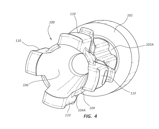
[00040] FIGS. 4-5B depict various details of the blood control component 100,
including an
elongate body 104 extending between a proximal end 104A and a distal end 104B
and defining
a central conduit 106 through which fluids can flow. A plurality of ribs 110
is disposed on an
outer surface of the body 104 such that the ribs longitudinally extend from
proximally past the
proximal end 104A of the body to the distal end 104B thereof. Each rib 110
radially extends
from the body 104 to define a contoured profile along the longitudinal length
thereof. The
body 104 and ribs 110 contribute to generally define a conical shape to the
blood control
component 100. Deviations from the conical shape are also possible in other
embodiments.
[00041] Each rib 110 further defines a notch 112 intermediately positioned
along the
longitudinal length of the rib, as well as a protrusion 114 at the proximal
end of the rib. As
seen in FIG. 3, the notch 112 of each rib 110 receives a portion of an annular
ridge 120 defined
on an inner surface of the catheter hub cavity 46A to keep the blood control
component 100 in
place within the cavity before actuation. Correspondingly, the protrusions 114
of each rib 110
engage with the annular ridge 120 when the blood control component 100 is
actuated so as to
-8-
CA 03034478 2019-02-20
WO 2018/049413 PCT/US2017/051214
prevent further distal movement thereof past its intended length of travel.
The body 104 defines
a channel 126 between adjacent ribs 110, thus providing four fluid flow
channels in the
illustrated embodiment. Note that in one embodiment one or more ribs 110 can
be offset along
the longitudinal length thereof such that a proximal portion of the rib
including the protrusion
114 is not longitudinally aligned with (as in FIGS. 5A and 5B), but rather
circumferentially
offset from, a more distal portion of the rib.
[00042] FIGS. 6A-6C depict details of the blood control component 100
according to
another embodiment, wherein the body 104 defines a plurality of channels 126
disposed about
the conduit 106. An intermediate, annular shoulder 128 is also defined by the
body 104.
[00043] FIGS. 7A-7C depict various stages of operation of the blood control
component 100
of FIGS. 6A-6C, though the principles described here also apply to the
embodiment shown in
FIGS. 4-5B as well. In particular, FIGS. 7A and 7B show the blood control
component 100 in
a relatively proximal position, also referred to herein as an un-actuated
state, wherein the
annular ridge 120 is received within the notches 112 (below the shoulders 128)
of each rib 110
of the blood control component. In this position, the distal end 104B of the
body 104 does not
protrude through the valve 102 that is positioned distal to the blood control
component and
thus no fluid is able to pass through the catheter 42, as desired. The valve
102 in the closed
position thus prevents blood leakage through the catheter 42, such as when the
catheter has
been placed within the patient but no external connection has been made to the
catheter hub
46.
[00044] In contrast, FIG. 7C shows the blood control component 100 in a
relatively distal
position, also referred to herein as an actuated state, wherein the blood
control component has
been distally advanced (such as by insertion of a male luer connector into the
catheter hub 46)
such that the distal end 104B thereof has penetrated through the leaflets 102A
of the valve 102,
thus providing a fluid path through the valve via the conduit 106 of the blood
control
component. Further distal advancement of the blood control component 100 is
prevented by
engagement of the protrusions 114 against the annular ridge 120. As mentioned,
the distal
movement of the blood control component 100 is caused by the insertion into
the catheter hub
cavity 46A by a luer connector or other apparatus that can be operably
connected to the catheter
hub 46.
-9-
CA 03034478 2019-02-20
WO 2018/049413 PCT/US2017/051214
[00045] In accordance with the present embodiment, the blood control component
100 is
configured to eliminate an entrapment zone between the blood control component
and the valve
102 after the blood control component has pierced the valve in its actuated
state. Specifically,
and with respect to the embodiment shown in FIGS. 4-5B, the ribs 110 cause
additional
deformation of the leaflets 102A of the valve 102 when the blood control
component pierces
the valve, as seen in FIG. 11. This in turn prevents partial sealing of the
leaflets 102A to the
exterior surface of the blood control component body 104, thus providing
spacing therebetween
and additional fluid flow paths via the channels 126 between the exterior
surface of the blood
control component body 104 and the valve leaflets. Thus, fluid is able to flow
through the
catheter hub cavity 46A not only internal to the blood control component body
104 via the
conduit 106 but also external to the blood control component body via the
channels 126, which
are made patent by the interaction of the ribs 110 with the valve leaflets
104A. This fluid flow
external to the blood control component 100 assists in moving fluid through
the entirety of the
hub cavity 46A, thus desirably preventing fluid flow stagnation in the region
between the blood
control component 100 and the valve 102.
[00046] Note that in the present embodiment an outer termination point of each
slit 103 that
form the leaflets 102A defines a staggered termination point, as seen in FIG.
11. Note also that
the ribs described herein are but one example of one or more extended surfaces
that can be
included with the blood control component to enable additional fluid flow
channels to be
defined on an outer surface of the blood control component to enable fluid
flow about the
exterior of the blood control component when the blood control component
pierces the valve.
Examples of other extended surfaces include bumps, annular surfaces, fins,
etc. These and
other embodiments are therefore contemplated.
[00047] The blood control component 100 of FIGS. 6A-6C operates similarly to
that
described immediately above in connection with FIGS. 4-5B, wherein the
channels 126 provide
fluid flow in addition to the conduit 106 so as to prevent fluid flow
stagnation between the
blood control component 100 and the valve 102.
[00048] FIGS. 8A-8F depict various details regarding the aforementioned needle
hub 14 of
the insertion device 10, which includes an elongate body 140 extending between
a proximal
end 140A and a distal end 140B. A slot 142 extends longitudinally along the
length of the
body 140 and is sized for receiving a portion of the length of the needle 16
therein. As
mentioned, the ridge 144 is included on the proximal end 140A of the needle
hub and provides
-10-
CA 03034478 2019-02-20
WO 2018/049413 PCT/US2017/051214
a surface against which the spring 50 can act to retract the needle hub and
attached needle 16
into the cavity of the housing 12. The slot 142 defines a volume 146 within
which the above-
described flash indicator 80 can be received.
[00049] Note that the slot 142 is configured so that differing sizes of needle
can be received
and affixed therein. To that end, the slot 142 includes three shoulders 148 to
support the needle
16 within the slot 142. Not that the proximal edge of each of the shoulders
148 is relatively
abrupt in shape so as to prevent spillage of a liquid epoxy adhesive that is
placed in the slot
142 proximate the shoulders to secure the needle 16 within the slot.
[00050] Embodiments of the invention may be embodied in other specific forms
without
departing from the spirit of the present disclosure. The described embodiments
are to be
considered in all respects only as illustrative, not restrictive. The scope of
the embodiments is,
therefore, indicated by the appended claims rather than by the foregoing
description. All
changes that come within the meaning and range of equivalency of the claims
are to be
embraced within their scope.