Note: Descriptions are shown in the official language in which they were submitted.
CA 03034741 2019-02-22
WO 2018/058358 PCT/CN2016/100528
SYSTEM AND METHOD FOR PARALLELIZATION OF CPU AND GPU
PROCESSING FOR ULTRASOUND IMAGING DEVICES
BACKGROUND
1. Technical Field
[0001] The present disclosure relates generally to ultrasound imaging
devices, and, more
particularly, to a system and method for parallelization of CPU and GPU
processing of
ultrasound imaging devices.
2. Discussion of Related Art
[0002] An ultrasound system has become a popular diagnostic tool since it
has a wide range
of applications. Specifically, due to its non-invasive and non-destructive
nature, the ultrasound
system has been extensively used in the medical profession. Modern high-
performance
ultrasound systems and techniques are commonly used to produce two or three-
dimensional
images of internal features of an object (e.g., human organs).
[0003] The ultrasound system generally uses a probe containing a wide
bandwidth transducer
to transmit and receive ultrasound signals. The ultrasound system forms images
of human
internal tissues by electrically exciting an acoustic transducer element or an
array of acoustic
transducer elements to generate ultrasound signals that travel into the body.
The ultrasound
signals produce ultrasound echo signals since they are reflected from body
tissues, which appear
as discontinuities to the propagating ultrasound signals. Various ultrasound
echo signals return
to the transducer element and are converted into electrical signals, which are
amplified and
processed to produce ultrasound data for an image of the tissues.
[0004] The ultrasound system employs an ultrasound probe containing a
transducer array for
transmission and reception of ultrasound signals. The ultrasound signals are
transmitted along
¨1¨
CA 03034741 2019-02-22
WO 2018/058358 PCT/CN2016/100528
scan lines aligned with the direction of a scan head of the ultrasound probe.
The ultrasound
system forms ultrasound images based on the received ultrasound signals. The
technique of
transmitting the ultrasound signals by steering the scan lines has been used
to obtain an
ultrasound image having a wider view angle.
[0005] Moreover, an ultrasound imaging system may include an ultrasound
diagnostic unit
and an image processing unit. The ultrasound diagnostic unit may transmit
ultrasound signals to
a target object and form, for example, 12-bit data based on echo signals. The
image processing
unit may form an ultrasound image based on the 12-bit data. The image
processing unit may
also include a digital signal processing unit (DSP), a digital scan converter
(DSC) and a central
processing unit (CPU). The DSP may be operable to process the 12-bit data to
form 12-bit raw
data for forming a brightness (B) mode image, an M mode image, or a color
Doppler mode
image. The DSC may be operable to scan-convert the raw data to thereby output
scan-converted
data suitable for a display format. The CPU may be operable to control
operations of the DSP,
DSC, and a display unit. Also, the CPU may be further operable to perform
filtering and
rendering upon the scan-converted data to thereby form pixel data for image
modes.
[0006] The rendering and formation of the pixel data performed in the CPU
may require a
large amount of data operations so that fewer CPU resources are available for
other processes
and power consumption by the CPU becomes higher. In addition, the CPU has to
control data
input/output at the DSP and DSC. Thus, an excessive load may be applied to the
CPU in
forming the ultrasound image so that the CPU is not available to provide a
higher frame rate of
ultrasound images. Accordingly, there is a need for systems and methods for
relieving loads
from the CPU, and providing a higher frame rate of ultrasound images.
¨2¨
CA 03034741 2019-02-22
WO 2018/058358 PCT/CN2016/100528
SUMMARY
[0007] In one aspect, the present disclosure is directed to an ultrasound
imaging system
including a transducer array, an ultrasound frontend, and a processing
apparatus. The transducer
array has a plurality of transducer elements, each of the plurality of
transducer elements
configured to transmit acoustic energy to a region of interest and receive
reflected acoustic
energy. The ultrasound frontend samples the reflected acoustic energy to
generate radio
frequency (RF) data. The processing apparatus includes a central processing
unit (CPU), a first
in/first out (FIFO) buffer, and a graphical processing unit (GPU). The CPU
receives the RF data
including RF frames and the FIFO buffer includes a plurality of memory blocks
for storing the
RF frames, wherein a size of each memory block is equal to the size of a
single RF frame. The
GPU reads the RF frames from the plurality of memory blocks of the FIFO buffer
and
reconstructs an image.
[0008] In the disclosed embodiments, the ultrasound imaging system further
comprises a
display for displaying a reconstructed image of the region of interest.
[0009] In the disclosed embodiments, the image is reconstructed by
performing envelope
detection, compounding, and post-processing.
[00010] In the disclosed embodiments, the number of the plurality of memory
blocks of the
FIFO buffer is greater than or equal to (t2 + t3) / ti, where ti is the time
that the CPU receives
one RF frame, t2 is the time that the GPU reads one RF frame, and t3 is the
time that the GPU
performs envelope detection, compounding, and post-processing.
[00011] In the disclosed embodiments, the CPU receives the RF frames and the
GPU reads
the RF frames, in a parallel manner.
¨3¨
CA 03034741 2019-02-22
WO 2018/058358 PCT/CN2016/100528
[00012] In the disclosed embodiments, the number of the plurality of
transducer elements is
128.
[00013] In the disclosed embodiments, the acoustic energy is transmitted in
plane waveform,
which has a plurality of steering angles. The number of steering angles is 11.
[00014] In the disclosed embodiments, the GPU reads a single memory block of
the FIFO
buffer to process one RF frame.
[00015] In the disclosed embodiments, the GPU performs beamforming processing
by delay-
and-sum operations in a parallel manner.
[00016] In one aspect, the present disclosure is directed to an ultrasonic
imaging method. The
method includes transmitting acoustic energy to a region of interest by a
transducer array
including a plurality of transducer elements, receiving reflected acoustic
energy, digitally
sampling the reflected acoustic energy to generate RF data, receiving the RF
data including RF
frames by a central processing unit (CPU), storing a RF frame in a memory
block of a plurality
of memory blocks of a first in/first out (FIFO) buffer; reading the RF frame
by a graphics
processing unit (GPU) from the memory block of the FIFO buffer, and
reconstructing an image
based on the RF frame by the GPU. The size of each memory block is equal to
the size of a
single RF data.
[00017] In the disclosed embodiments, the method further includes displaying
the
reconstructed image of the region of interest on a display.
[00018] In the disclosed embodiments, reconstructing the image includes
performing envelope
detection, compounding, and post-processing by the GPU.
[00019] In the disclosed embodiments, the size of each memory block of the
FIFO buffer is
greater than or equal to (t2 + t3) / ti, where ti is the time that the CPU
receives one RF frame, t2
¨4¨
CA 03034741 2019-02-22
WO 2018/058358 PCT/CN2016/100528
is the time that the GPU reads the RF frame from the memory block, and t3 is
the time that the
GPU reconstructs the image.
[00020] In the disclosed embodiments, receiving the RF data and reading the RF
frame are
performed in a parallel manner.
[00021] In the disclosed embodiments, the number of plurality of transducer
elements is 128.
[00022] In the disclosed embodiments, the acoustic energy is transmitted in
plane waveform,
which includes steering angles. The number of steering angles is 11.
[00023] In the disclosed embodiment, the method further includes performing
beamforming
process on the RF frame by the GPU.
[00024] In the disclosed embodiments, the beamforming processing is performed
by delay-
and-sum operation in a parallel manner.
[00025] In the disclosed embodiments, the method further includes performing
beamforming
process on the RF frame by the GPU.
[00026] Further, to the extent consistent, any of the aspects described herein
may be used in
conjunction with any or all of the other aspects described herein.
[00027] The Summary is provided to introduce a selection of concepts in a
simplified form
that are further described below in the Detailed Description. This Summary is
not intended to
identify key or essential features of the claimed subject matter, nor is it
intended to be used in
determining the scope of the claimed subject matter.
BRIEF DESCRIPTION OF THE DRAWINGS
[00028] Various aspects of the present disclosure are described hereinbelow
with reference to
the drawings, which are incorporated in and constitute a part of this
specification, wherein:
¨5¨
CA 03034741 2019-02-22
WO 2018/058358 PCT/CN2016/100528
1000291 FIG. I illustrates a top level architecture of an ultrasound
imaging system, in
accordance with aspects of the present disclosure;
1000301 FIG. 2 illustrates an image reconstruction procedure of a
conventional ultrasound
imaging system;
1000311 FIG. 3 illustrates an image reconstruction procedure, in accordance
with aspects of
the present disclosure;
1000321 FIGS, 4A and 4B illustrate CPU (central processing unit) and GPU
(graphics
processing unit) working flow, where FIG. 4A is the working flow when L_FIFO
<(t2 + t3) I ti,
and FIG. 413 is the working flow when L_FIFO > (12 + t3) / ti, in accordance
with aspects of the
present disclosure;
: 1000331 .. FIG. 5 illustrates a block diagram showing receiving beamforming
with time delays,
in accordance with aspects of the present disclosure; and
1000341 FIG. 6 illustrates data-level parallelism in delay-and-sum
operations, in accordance
with aspects of the present disclosure.
DETAILED DESCRIPTION
1000351 A detailed description is provided with reference to the
accompanying drawings. One
of ordinary skill in the art will realize that the following description is
illustrative only and is not
in any way limiting. Other embodiments of the present disclosure will readily
suggest
themselves to such skilled persons having the benefit of this disclosure.
1000361 As discussed in further detail below, various embodiments of
transducer elements of
an ultrasound probe communicatively coupled to an imaging system are provided
with respect to
waveform generation proximate to the transducer elements of the ultrasound
probe. In one
embodiment, the ultrasound probe is electronic, reusable, capable of precise
waveform timing
¨6 -
RECTIFED SHEET ( RULE 91)
CA 03034741 2019-02-22
WO 2018/058358 PCT/CN2016/100528
and intricate waveform shaping for a plurality of independent transducer
elements, and capable
of communicating analog or digitized data to the imaging system.
[00037] The present disclosure describes a method for increasing frame rates
of ultrasound
systems by parallelizing CPU and GPU. First, the CPU receives RF data from the
ultrasound
frontend via a USB 3.0 port, and then stores the RF data in the First In/First
Out buffers (FIFO).
Second, the GPU reads RF data from a FIFO buffer and then performs
beamforming, envelope
detection, compounding, and post processing. Third, the reconstructed image is
displayed on one
or more display screens. By migrating beamforming from the ultrasound frontend
to the GPU,
the cost of the ultrasound system may be reduced. Further, by parallelizing
the receiving of RF
data and beamforming, the frame rate is also further increased.
[00038] FIG. 1 illustrates an ultrasound imaging system 100, in accordance
with aspects of the
present disclosure. Ultrasound imaging is a non-invasive subsurface imaging
modality widely
used in diagnosis, screening, and as an intra-operative surgical guide. FIG. 1
depicts a
transducer 110, an ultrasound frontend 120, a universal serial bus (USB) port
130, a computing
device 140, and a display 150.
[00039] The
transducer 110 includes a plurality of transducer elements, which are
typically
formed of a piezoelectric material and referred to as a transducer array. Scan
lines or channels
correspond to each transducer element of the transducer array. When electric
signals having a
frequency in the radio frequency (RF) range are provided to each transducer
element of the
transducer 10, each transducer element is energized to generate acoustic
signals.
[00040]
When the plurality of transducer elements of the transducer generate an
ultrasound
waveform and transmit them towards a target, the plurality of transducer
elements of the
¨7¨
CA 03034741 2019-02-22
WO 2018/058358 PCT/CN2016/100528
transducer use time delays based on distance differences between each
transducer element and
the target so that each generated ultrasound waveform can reach the target at
the same time.
[00041] The ultrasound waveforms are transmitted along scan lines or channels
aligned with
the direction of a scan head of an ultrasound probe. The ultrasound waveform
is reflected by the
target. The reflected waveforms can be detected by the corresponding
transducer elements of the
transducer 110, which in turn generates electric signals. Since the temporal
shape of the
reflected signals or echoes is similar to a temporal shape of RF data, the
generated electrical
signals based on the echoes are called RF data.
[00042] In an aspect, the transducer array 110 may include a multi-element
linear, curved
linear, phased linear, sector, or wide view array. For example, the transducer
array 110 may
provide for 16, 32, 64 or 128 channels. In one embodiment, the transducer
array 110 includes
128 channels.
[00043] The received signals, echoes of the transmitted acoustic signal are
converted by the
transducer to RF data and then transmitted to the ultrasound frontend 120. The
transducer array
110 may be incorporated into the ultrasound frontend 120. The ultrasound
frontend 120 may
include a signal receiver and an analog-to-digital converter (ADC). The signal
receiver may
perform, for example, low-noise amplification, programmable gain
amplification, and low-pass
filtering, and the ADC digitally samples the RF data. According to an aspect
of the present
disclosure, beam forming is not performed by the ultrasound frontend 120 but
by the computing
device 140. Beamforming is a process which combines RF data received from the
plurality of
transducer elements of the transducer 110 to a single signal which is focused
at a specific spatial
location in the space of interest. Thus, the computing device 140 does not
have to wait until the
¨8¨
CA 03034741 2019-02-22
WO 2018/058358 PCT/CN2016/100528
ultrasound frontend 120 finishes beamforming. In this way, the total
processing time can be
decreased
[00044] In an aspect, the transducer array may include 128 transducer
elements, which
corresponds to 128 lines or channels. As a result, a single frame (image)
includes 128 lines of
RF data. During analog-to-digital conversion, every single line is sampled as
4096 points.
Every point occupies 2 bytes, which means that the size of one frame
(hereinafter a RF frame) of
RF data is: 4096*128*2 = 1 M bytes. After performing analog-to-digital
conversion, the digital
RF data is transmitted to the computing device 140 via the USB 3.0 port 130.
The normal
transmission speed of the USB 3.0 port 130 is 300 MB/s, which means that 3.33
ms are needed
to transmit one RF frame of RF data from the ultrasound frontend 120 to the
computing device
140.
[00045] The computing device 140 performs beamforming and post processing.
Post
processing of the single beam formed signal results in the construction of
ultrasound images.
The images is transmitted to and displayed on a screen of the monitor 150.
[00046] FIG. 2 illustrates an image reconstruction procedure of a conventional
ultrasound
imaging system of FIG. 1. The image reconstruction system 200 includes a data
transmission
and acquisition unit 210 and a computing device 220. The data transmission and
acquisition unit
210 transfers RF data to the computing device 220. The computing device 220
may be a
personal computer. The computing device 220 includes a CPU 230, a GPU 240, and
a display
290. The CPU 230 is capable of functioning as at least a USB host controller
232. The GPU
240 is capable of functioning as a beamformer 250, an envelope detection unit
260, a
compounding unit 270, and an image post-processing unit 280. The CPU 230
controls the USB
host controller 232 to receive the RF data from the data transmission and
acquisition unit 210 via
¨9¨
CA 03034741 2019-02-22
WO 2018/058358 PCT/CN2016/100528
a transmission port, for example a USB 3.0 port. The RF data is processed by
the GPU 240, as
the data is received from the CPU 230. Since the CPU 230 and the GPU 240
serially process the
RF data, the CPU 230 cannot provide received RF data to the GPU 240 until the
GPU 240
finishes processing RF data, and the GPU 240 has to wait until the CPU 230
finishes reception of
RF data. Thus, serial processes between the CPU 230 and the GPU 240 cause
unnecessary
waiting times in the CPU 230 and/or the GPU 240.
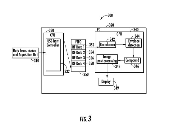
[00047] FIG. 3 illustrates an image reconstruction system in accordance with
aspects of the
present disclosure.
[00048] The image reconstruction system 300 includes a data transmission and
acquisition
unit 310, a computing device 320, and a display 349. The data transmission and
acquisition unit
310 transfers data to the computing device 320. The computing device 320 may
be a personal
computer, a tablet, or a smart device (e.g., a smartphone). The computing
device 320 includes a
CPU 330, a GPU 340, and a FIFO buffer 350. The CPU 330 may include at least a
USB host
controller 332 so as to control a data transfer port (e.g., the USB 3.0 port
130 of FIG. 1) to
receive RF data from the data transmission and acquisition unit 310. When the
RF data is
received, the CPU 330 processes the RF data to form RF frames.
[00049] The FIFO buffer 350 is coupled with the CPU 330 and the GPU 340. The
CPU 330
stores each RF frame in the FIFO buffer 350 when the FIFO buffer 350 has
unoccupied spaces,
and then receives RF frames. The FIFO buffer 350 may include a plurality of
memory blocks
352, 354, 356, 358, etc. One skilled in the art may contemplate any size FIFO
buffer having
thousands of memory blocks for storing data. The size of one memory block
(e.g., 352) of the
FIFO buffer 350 may be equal to the size of one RF frame of the RF data. Thus,
each RF frame
is stored in one memory block (e.g., 352) of the FIFO buffer 350.
¨10¨
CA 03034741 2019-02-22
WO 2018/058358 PCT/CN2016/100528
[00050] The GPU 340 may include a beamformer 342, an envelope detection unit
344, a
compounding unit 346, and an image post-processing unit 348. When the GPU 340
reads a RF
frame from one memory block (e.g., 352) of the FIFO buffer 350, the beamformer
342 processes
the RF frame by delaying and summing digital data to generate a single signal
which is focused
at a specific location in an image. The envelope detection unit 344 detects
envelope of the
signals generated by the beamformer 342, thus removing the carrier signal.
Since the image
generated from the envelop detection unit 344 includes speckle errors (e.g.,
coherent noise),
which result from constructive and destructive wave interference of
reflections of the ultrasound
waves generated by the plurality of transducer elements of the transducer 110
of FIG. 1.
[00051] The compounding unit 346 removes the speckle errors. For example, the
compounding unit 346 may remove the speckle errors by averaging pixel values
located at the
same location of multiple images obtained by using different steering angles.
The compounding
unit 346 may perform removal of the speckle errors by any means readily
available to a person
having ordinary skill in the art. After the compounding process, an ultrasound
image is
generated.
[00052] The image post-processing unit 348 may perform enhancement of the
generated
ultrasound image automatically or manually by a medical professional or
technician to
reconstruct the generated image. The reconstructed image is then displayed on
a screen of the
display 349.
[00053] The GPU 340 can process RF frames, from the FIFO buffer 350, at a
different rate
than the rate that the CPU 330 is receiving the RF data. Thus, by selecting an
optimal number of
the memory blocks of the FIFO buffer 350, the total process time can be
reduced.
¨11¨
CA 03034741 2019-02-22
WO 2018/058358 PCT/CN2016/100528
[00054] L FIFO is defined as a number of memory blocks 352, 354, 356, 358,
etc. of the
FIFO buffer 350 and may be greater than (t2 + t3) / ti, where ti is the time
for the CPU 330
receiving one RF frame from data transmission and acquisition unit 310, t2 is
the time for the
GPU 340 performing beamforming of the RF frame, and t3 is the time for the GPU
340
performing compounding, post processing, and display of the reconstructed
image.
[00055] FIGS. 4A and 4B illustrate CPU and GPU working flow 400, where FIG. 4A
is the
working flow when L FIFO < (t2 + t3) / ti, and FIG. 4B is the working flow
when L FIFO >
(t2 + t3) / ti, in accordance with aspects of the present disclosure.
[00056] When L FIFO < (t2 + t3) / ti, the CPU receiving workflow is
represented as 410 and
the GPU processing workflow is represented as 420, as shown in FIG. 4A. When L
FIFO >
(t2 + t3 ) / ti, the CPU receiving workflow is represented as 430 and the GPU
processing
workflow is represented as 440, as shown in FIG. 4B.
[00057] In one embodiment of the present disclosure, ti is around 3.33
milliseconds (ms), t2
is around 2 ms, t3 is around 6 ms, and N is 11, where N is a number of
different steering angles
of the ultrasonic plane waves. With these values, (t2 + t3 ) / ti = (2 + 6) /
3.33 2.42.
[00058] Referring back to FIG. 4A, when L FIFO is less than (t2 + t3) / ti,
for example
L FIFO is 2, the CPU can store up to two RF frames in the FIFO buffer.
Assuming that the CPU
starts storing the current first RF frame for the time 412, which is ti, after
the GPU has
completed reading the previous second last RF frame (in this example, the
previous (N-1)-th RF
frame), the current second RF frame can be stored in the second memory block
for the time 414,
which is also ti, after the current first RF frame is stored because the
previous N-th RF frame
412 has been read before completion of storing the current first RF frame.
After completion of
reading the previous N-th RF frame for the time 421, which is t2, the GPU
performs the image
¨12¨
CA 03034741 2019-02-22
WO 2018/058358 PCT/CN2016/100528
post-processing for the time 422 (i.e. t3). The GPU completes its reception of
the previous N-th
RF frame and the image post-processing for 8 ms, which is the sum of the times
421 and 422 or
t2 and t3, while the CPU completes reception and storing of the current first
and second RF
frames for the sum of the times 412 and 414 or 6.66 ms. Thus, the CPU cannot
store the current
third RF frame for the time 416, 1.67 ms because the GPU can read the current
first RF frame
only after the sum of the times 421 and 422 or 8 ms. In other words, the time
416, 1.67 ms, is
wasted at the CPU.
[00059] After storing the current first and second RF frames in the memory
blocks, the CPU
can store (k - 1)-th and k-th RF frames without wasting times because the GPU
can read a RF
frame faster than the CPU stores a RF frame. Thus, the total time for storing
N RF frames by the
CPU is t2 + t3 + (N - L FIFO) * ti. For example, when N is 11, the total time
is 37.97 ms. The
total time for processing N RF frames by the GPU is 3 * t2 + (N ¨ 4) * tl +
t3, which is 35.31,
which is smaller than the total processing time by the CPU.
[00060] Referring back to FIG. 4B, when L FIFO is greater than or equal to (t2
+ t3) / ti, for
example L FIFO is 3, the CPU can store up to three RF frames of RF data in the
FIFO buffer.
Assuming that the CPU starts storing the current first RF frame for the time
412, which is ti,
after the GPU completes reading the previous second last RF frame (in this
example, the
previous (N - 1)-th RF frame), the current second and third RF frames can be
stored in the
second and third memory blocks for the times 414 and 416, after the current
first RF frame is
stored because the previous N-th RF frame 412 has been read before completion
of storing the
current first RF frame. After completion of reading the previous N-th RF frame
for the time 421,
the GPU performs the image post-processing for the time 422. The GPU completes
its reception
of the previous N-th RF frame and the image post-processing for 8 ms. Since
there are three
¨13¨
CA 03034741 2019-02-22
WO 2018/058358 PCT/CN2016/100528
memory blocks, the CPU completes reception and storing of the current first to
third RF frames
for the sum of the times 412, 416, and 418 or 9.99 ms. Since the GPU can read
the first RF
frame after the 8 ms, the CPU can continuously store the current fourth RF
frame and the
following RF frames without wasting times. Thus, under this example, the total
time processed
at the CPU is N * ti. If N is 11, the total time is 36.63 ms, which is smaller
than the total time
calculated for the case in FIG. 4A.
[00061] Therefore, in FIG. 4B, parallelization of the CPU receiving and GPU
processing by
utilizing an appropriate number of memory blocks of the FIFO buffer can reduce
the total
processing time at the CPU. Because ti * N > t2 * N + t3, the total time is
equal to the total time
at the CPU. Consequently, with reference to FIGS. 3 and 4B, the minimization
of the total time
for the processing between the CPU and GPU can be achieved by using an
appropriate number
of memory blocks of the FIFO buffer based on the reception and processing
times of one RF
frame by the CPU and GPU, respectively. Thus, the optimized number of memory
blocks of the
FIFO buffer allows for a faster frame rate. Having an appropriate number of
memory blocks, the
FIFO buffer is continuously available for receiving RF frames at the CPU, and
the GPU reads
and processes RF data without delaying the total processing time for one RF
frame.
[00062] In an aspect, if L FIFO is set as the minimum value that is greater
than or equal to
(t2 + t3 ) / ti, the memory can be used efficiently without wasting memory
space that is not
needed. In this way, each of the plurality of memory blocks of the FIFO buffer
is optimally
utilized based on the processing times of one RF frame by the CPU and the GPU.
[00063] FIG. 5 illustrates a block diagram 500 showing beamforming with
temporal delays in
accordance with aspects of the present disclosure. As described above with
respect to the
transducer elements of the transducer 110 of FIG. 1, the transducer elements
use temporal delays
¨14¨
CA 03034741 2019-02-22
WO 2018/058358 PCT/CN2016/100528
while generating ultrasound waveforms. Likewise, the beamforming uses temporal
delays. For
example, if the first transducer generates an ultrasound waveform by delaying
a temporal period,
the beamforming also delays the same temporal period for the RF data
corresponding to the
ultrasound waveform generated by the first transducer element.
[00064] For example, FIG. 5 shows M scan lines meaning that the RF frame is
generated by
M transducer elements. For example, input RF data 510, yk(t), may be obtained
from the
(k + 1)-th transducer element, is filtered by a filter 520, and temporarily
delayed by a period Ak,
which corresponds the temporal delay for the (k + 1)-th transducer element,
where k = 0, 1,
2, . . M - 1. All delayed RF data 635, wk, are then summed to output an output
data 550, z(t),
which is a pixel value for a pixel in the ultrasound image.
[00065] In order to reduce the time for calculating corresponding positions in
RF data from
the plurality of transducer elements, N Steer mapping tables are calculated
before beamforming,
and stored in the mapping tables in a 2-D texture memory. N Steer is the
number of steering
angles when the ultrasound probe transmits plane waves, and the size of every
mapping table is
N * W RF, where W RF is the number of lines in the RF data and N is the number
of pixels in a
reconstructed image. Thus, every pixel in the reconstructed image is generated
from and
calculated by adding W RF points of RF data together via the summer 540.
[00066] In one embodiment, the transmit circuitry may be configured to operate
the
transducer array 110 such that the acoustic energy emitted is directed or
steered as plane waves.
For example, a processing circuitry may impart respective time delays 530
(FIG. 5) to generate
temporally offset pulsed waveforms that are applied to respective transducer
elements. These
temporal offsets result in different activation times of the respective
transducer elements such
¨15¨
CA 03034741 2019-02-22
WO 2018/058358 PCT/CN2016/100528
that the waveform of acoustic energy emitted by the transducer array 110 is
effectively steered
or directed in a particular direction with respect to the surface of the
transducer array 110.
[00067] Thus, by adjusting the time delays 530 associated with the pulsed
waveforms that
energize the respective transducer elements, the ultrasonic plane waves can be
directed toward or
away from an axis associated with the surface of the transducer array 110 by a
specified angle (0)
and focused at a fixed range within the patient tissue. In such an
implementation, a sector scan
may be performed by progressively changing the time delays in successive
excitations. The
steering angle 0 is thus incrementally changed to steer the transmitted plane
wave in a succession
of steering directions.
[00068] The echo signals produced by each burst of acoustic energy are
reflected by structures
or structure interfaces or target tissue located at successive ranges along
the ultrasonic plane
waves. The echo signals are sensed separately by each transducer element and a
sample of the
echo signal magnitude at a particular point in time represents the amount of
reflection occurring
at a specific range.
[00069] The beamformer 342 may be implemented by a programmable logic device.
The
programmable logic device filters, interpolates, demodulates, phases, applies
apodization, delays
and/or sums the received signals, which are functions of the beamformer 342.
The
programmable logic device digitally controls the delays and characteristic of
transmit waveforms,
and generates transmit waveforms from memory, which are functions of the
transmit waveform.
The programmable logic device may also implement relative delays between the
waveforms as
well as filter, interpolate, modulate, phase, and apply apodization. The
programmable logic
device controlling the beamformer 342 to perform functions to process the
plurality of signals
associated with such multi-element electrically scanned arrays.
¨16¨
CA 03034741 2019-02-22
WO 2018/058358 PCT/CN2016/100528
[00070] FIG. 6 illustrates data-level parallelism 600 in delay-and-sum
operations, in
accordance with aspects of the present disclosure.
[00071] To reconstruct an image with N pixels, M = N CUDA threads are created
and M
threads are assigned to each pixel, where M is empirically optimized for each
imaging
application. The threads assigned to adjacent pixels are grouped together in
the same thread
block to maximize the memory access efficiency by utilizing the spatial
locality of the raw data
samples stored in the 2-D texture memory. CUDA is a parallel computing
platform and
programming model invented by NVIDIA . It enables dramatic increases in
computing
performance by harnessing the power of the GPU.
[00072] In prior approaches, a good amount of time was wasted to populate
delay tables and
to find points in the tables that correspond to a pixel in the reconstructed
image. In the present
disclosure, before performing the beamforming, the delay table is populated
and stored in the
GPU so that the GPU can perform a look-up in the table to find relevant
positions in the 3-D
texture memory and add them together, as shown in FIG. 7. This GPU
reconstruction approach
is faster than prior approaches because performing look-ups in the pre-stored
table is faster than
populating/repopulating the delay table before each beamforming. In one
embodiment, the
ultrasound system of the present disclosure only needs to populate N Steer
delay tables (one per
each steering angle) and store them in FIFO buffers. As a result, when
performing beamforming,
embodiments of the present disclosure only need to perform look-ups in the
table and do not
need to repopulate the table.
[00073] Advantages of the present disclosure further include adding FIFO
buffers to make
sure the RF data received by the CPU and image reconstruction with the GPU are
performed in
parallel. The CPU continuously receives and stores digital RF data in memory
blocks of the
¨17¨
CA 03034741 2019-02-22
WO 2018/058358 PCT/CN2016/100528
FIFO buffer when the FIFO buffer is not full. The GPU reads the RF data from
the memory
blocks of the FIFO buffer when the memory blocks are not empty, and performs
beamforming,
compounding, post processing, and display. The size of one memory block of the
FIFO buffer is
the same as the size of one RF frame. Therefore, each RF frame is stored in
one memory block
of the FIFO buffer and the GPU only needs to read one memory block of the FIFO
buffer to get a
RF frame, and then performs the beamforming processing. In order to reduce the
whole
processing time, L FIFO may be greater than or equal to (t2 + t3) / ti.
[00074] There are many transducer array systems contemplated by the disclosed
embodiments.
Most of the description focuses on a description of a diagnostic medical
ultrasound system,
however, the disclosed embodiments are not so limited. The description focuses
on diagnostic
medical ultrasound systems solely for the purposes of clarity and brevity. It
should be
appreciated that disclosed embodiments apply to numerous other types of
methods and systems.
[00075] In a transducer array system, the transducer array is used to convert
a signal from one
format to another format. For example, with ultrasound imaging the transducer
converts an
ultrasonic wave into an electrical signal, while a radar system converts an
electromagnetic wave
into an electrical signal. While the disclosed embodiments are described with
reference to an
ultrasound system, it should be appreciated that the embodiments contemplate
application to
many other systems. Such systems include, without limitation, radar systems,
optical systems,
and audible sound reception systems.
[00076] Additionally, "code" as used herein, or "program" as used herein, may
be any
plurality of binary values or any executable, interpreted or compiled code
which may be used by
a computer or execution device to perform a task. This code or program may be
written in any
one of several known computer languages. A "computer," as used herein, may
mean any device
¨18¨
CA 03034741 2019-02-22
WO 2018/058358 PCT/CN2016/100528
which stores, processes, routes, manipulates, or performs like operation on
data. A "computer"
may be incorporated within one or more ultrasound imaging devices or one or
more electronic
devices or servers to operate one or more processors to run the ultrasound
imaging devices. It is
to be understood, therefore, that this disclosure is not limited to the
particular forms illustrated
and that it is intended in the appended claims to embrace all alternatives,
modifications, and
variations which do not depart from the spirit and scope of the embodiments
described herein.
[00077] Detailed embodiments of devices, systems incorporating such devices,
and methods
using the same as described herein. However, these detailed embodiments are
merely examples
of the disclosure, which may be embodied in various forms. Therefore, specific
structural and
functional details disclosed herein are not to be interpreted as limiting, but
merely as a basis for
the claims and as a representative basis for allowing one skilled in the art
to variously employ the
present disclosure in appropriately detailed structure.
[00078] As will be appreciated, as used herein the term "circuitry" may
describe hardware,
software, firmware, or some combination of these which are configured or
designed to provide
the described functionality, such as transmit beamforming, receive
beamforming, and/or scan
conversion.
[00079] The term "delay" is intended broadly to encompass both delaying and
advancing one
signal relative to another.
[00080] The term "module" may at least refer to a self-contained component
(unit or item)
that is used in combination with other components and/or a separate and
distinct unit of hardware
or software that may be used as a component in a system, such as an ultrasound
system including
a transducer array having a plurality of transducer elements. The term
"module" may also at
least refer to a self-contained assembly of electronic components and
circuitry, such as a stage in
¨19¨
CA 03034741 2019-02-22
WO 2018/058358 PCT/CN2016/100528
a computer that is installed as a unit. The term "module" may be used
interchangeably with the
term "unit."
[00081] The term "storage" may refer to at least data storage. "Data storage"
may at least
refer to any article or material (e.g., a hard disk) from which information is
capable of being
reproduced, with or without the aid of any other article or device. "Data
storage" may at least
refer to the holding of data in an electromagnetic form for access by a
computer processor.
Primary storage is data in random access memory (RAM) and other "built-in"
devices.
Secondary storage is data on hard disk, tapes, and other external devices.
"Data storage" may
also at least refer to the permanent holding place for digital data, until
purposely erased.
"Storage" implies a repository that retains its content without power.
"Storage" mostly means
magnetic disks, magnetic tapes and optical discs (CD, DVD, etc.). "Storage"
may also refer to
non-volatile memory chips such as flash, Read-Only memory (ROM) and/or
Electrically
Erasable Programmable Read-Only Memory (EEPROM).
[00082] The term "processing" may at least refer to determining the elements
or essential
features or functions or processes of one or more ultrasound imaging devices
for computational
processing. The term "process" may further refer to tracking data and/or
collecting data and/or
manipulating data and/or examining data and/or updating data on a real-time
basis in an
automatic manner and/or a selective manner and/or manual manner (continuously,
periodically
or intermittently).
[00083] While several embodiments of the disclosure have been shown in the
drawings, it is
not intended that the disclosure be limited thereto, as it is intended that
the disclosure be as broad
in scope as the art will allow and that the specification be read likewise.
Therefore, the above
description should not be construed as limiting, but merely as
exemplifications of particular
¨20¨
CA 03034741 2019-02-22
WO 2018/058358 PCT/CN2016/100528
embodiments. Those skilled in the art will envision other modifications within
the scope and
spirit of the claims appended hereto.
¨21¨