Note: Descriptions are shown in the official language in which they were submitted.
CA 03034743 2019-02-22
85024%45
1
A TURBOMACHINE ARRANGEMENT WITH A PLATFORM COOLING DEVICE FOR
A BLADE OF A TURBOMACHINE
FIELD OF INVENTION
[0001] The present invention particularly relates to a turbomachine
arrangement with
a platform cooling device that can be connected to a blade of a turbomachine,
particularly a
gas turbine engine.
BACKGROUND OF INVENTION
[0002] In modern day turbo machines various components of a turbomachine
operate
at very high temperatures. This is specifically true for components in a
turbine section of a gas
turbine engine. These components include blades and vanes within the turbine
section. These
blades and vanes typically are shaped in form of an airfoil and have further
elements
connected to it like platforms as boundary for the working fluid path. A blade
may also have a
root portion which is used to fix the blade to a turbine disc. High
temperatures during
operation of the turbomachine may damage the blade, hence cooling of the blade
component
is important. Cooling of all these components is generally achieved by passing
a cooling fluid
through the component or along the component. As cooling fluid typically air
from a
compressor of the turbomachine is used.
[0003] Besides it should be noted that turbine blades are typically cast
components
whereby the casting procedure allows to generate a hollow core within the
blade, which then
can be used to guide cooling fluid through the interior.
[0004] Such a blade typically includes an aerofoil portion, a root portion
and a blade
platform, the platform separating the aerofoil from the root portion.
Additionally, some blades
may comprise also a shroud at the tip of the aerofoil portion. Furthermore, a
root portion may
sometimes be followed by a neck portion before the platform begins. The neck
may extend
the root without having specific features for connecting to the disc. The
airfoil portion of the
CA 03034743 2019-02-22
1
85024445
2
blade is typically cooled by a cooling fluid through passages formed in the
airfoil portion of
the blades. Furthermore, film cooling may be used to cool the aerofoil and the
platform
portion by having various small holes allowing to pass air in a way that the
air builds a film or
cushion between the hot working fluid and the cooled surface. Eventually, the
cooling fluid
will mix with the hot working fluid within the main working fluid passage of
the turbine
section.
[0005] An aerofoil is defined by a leading edge directed to where the hot
working
fluid will come from during operation, and a trailing edge directed in the
direction of the fluid
flow of the working media. Furthermore, an aerofoil is defined by a suction
and a pressure
surface, depending on the curvature and the direction of rotation of the
blade.
[0006] Platforms may also be defined by a region close to the leading edge
and a
region close to the trailing edge, and furthermore, may be split in a region
at the suction side
of the aerofoil and a region at the pressure side of the aerofoil. At the
platforms different
temperatures arise depending on the location around the aerofoil. At different
locations of the
platform different amount of cooling is needed at the platform surface.
Cooling of the blade
platform may be difficult since most of the cooling air is provided to the
inner core of the
blade to cool the aerofoil. Nevertheless, surfaces exposed to the hot working
fluid provided
from the combustors may need specific cooling. Normally, cooling of blade
platforms is
achieved by providing film cooling by a flow of a portion of the cooling air
over the upper
surfaces of the blade platforms, however, manufacturing of film cooling holes
may be time
consuming and therefore costly.
[0007] Additionally, a root section or a neck section of a blade needs
adequate cooling
as otherwise possibly oxidation and cracking of the underside of the platforms
or the root may
OMIT.
[0008] Patent application EP 2 110 515 A2 shows a damper between two rotor
blades
which supports sealing and cooling of blade platforms. Patent application EP 2
728 114 Al
focuses on the cooling of the platform of a blade of a turbomachine by using a
platform
85024445
3
cooling device that can be connected to an underneath side of a blade
platform. Patent
application CH 703875 A2 shows an alternative design with an impingement plate
which may
be located preferably at the pressure side platform. All three documents focus
on impingement
cooling.
SUMMARY OF INVENTION
[0009] In some engines, a pressure side platform of cooled turbine blades
may
experience overheating. Therefore, it is an object of the present invention to
provide a
platform cooling device for a blade of a turbomachine to provide efficient
cooling.
[0010] This object is achieved by providing a turbomachine arrangement
with a
platform cooling device for a blade of a turbomachine. Furthermore, the
invention is related to
a turbomachine subsection comprising such a platform cooling device.
[0011] According to the invention, a turbomachine arrangement is provided
comprising a blade of a turbomachine and a platform cooling device for the
blade configured
to be positioned at a platform of the blade. The platform cooling device
comprises a
peripheral edge configured to be in contact with the platform. This peripheral
edge can also be
identified as circumferential edge, circumferential about and relative to the
platform cooling
device. It further comprises a first surface portion configured to form a
first cavity between
the platform cooling device and the platform, the first surface portion
comprising a plurality
of impingement holes configured to impinge onto the platform during operation
of the
turbomachine. Besides, it comprises also a second surface portion configured
to form a second
cavity between the platform cooling device and the platform and a barrier, the
barrier being
configured to be in contact with the platform, the barrier forming a
connection between two
sections of the edge and separating the first cavity from the second cavity
fluidically. In other
words, the barrier is a separating wall, wherein the wall is connecting two
sections of the
edge. According to the invention the platform cooling device and the blade are
separately
manufactured components, and the platform cooling device is connected at the
edge to the
Date Recue/Date Received 2020-05-29
CA 03034743 2019-02-22
85024445
4
blade, such that the first cavity and the second cavity are formed between the
platform cooling
device and the blade. Additionally, the blade comprises a cooling fluid supply
passage,
connecting a hollow blade core and the second cavity, for supplying of cooling
fluid to the
second cavity during operation. The first cavity is supplied, during
operation, with cooling
fluid via the impingement holes of the first surface portion.
[0012] The platform cooling device is configured to be positioned at a
platform of the
blade. The turbine arrangement defines the arrangement of a blade with a
connected platform
cooling device.
[0013] The platform cooling device could also be specified as a platform
cooling
screen.
[0014] The platform cooling device is advantageously not part of the
working fluid
path but is positioned underneath the platform of the blade. "Underneath"
means in this
respect the back or rear side of the platform, i.e. a surface not washed by
the working fluid.
[0015] Even though the blade is defined according to the invention to have
just a
platform and no further components are specified it is clear that the blade
comprises all its
typical components like an aerofoil, like the platform, like a root and
optionally also an neck
and optionally also a shroud.
[0016] The peripheral or circumferential edge is an elevated surface
region. It is
considered to be a rim with a flat top. The flat top of the rim follows
particularly the form of
the opposite platform surface to which it is going to be connected.
[0017] The contact between the circumferential edge and the platform is
advantageously a continuous connection between the two components. That means
that the
circumferential edge is also a fluidic barrier for cooling fluid.
[0018] According to the invention two distinct and separate cavities are
formed which
can be equipped with different cooling features. By this, specific adaptations
to the cooling
CA 03034743 2019-02-22
85024445
needs of the platform are possible by specific configuration of the platform
cooling device.
The first surface portion with the impingement holes is advantageously close
to a trailing edge
of the platform and/or close to a midsection of the platform. The second
surface portion may
be close to a leading edge of the to be cooled platform.
[0019] By using this invention particularly for a pressure platform section
of the blade,
the platform can be cooled in a highly controlled way which allows the blade
to operate in
higher temperatures without risking thermal damages to the blade.
[0020] Additionally, the amount of cooling fluid can be optimized so that
the overall
efficiency of the turbomachine is improved.
[0021] According to the invention, a plurality of impingement holes is
located at the
first surface portion. According to a first embodiment the second surface
portion may be
completely free of impingement holes. This allows to configure the cooling
fluid in a way that
only in one region impingement cooling is performed. Alternatively, the second
surface
portion may also comprise impingement holes but advantageously in a different
number and
in a different configuration compared to the first surface portion. In
particular, the pattern of
impingement holes at the second surface portion may be different that the
pattern of
impingement holes at the first surface portion. Furthermore or additionally,
the cooling hole
diameters of the impingement holes of the different regions may be different
to another.
[0022] According to an embodiment, a first segment of the edge may be
configured to
connect with the root or neck section of the blade. Furthermore, a second
segment of the blade
may be configured to connect with a rear or back surface of the platform of
the blade. In
consequence, the first surface portion and the second surface portion may be
curved. By this
configuration the platform cooling device is able to cover the cavity formed
underneath the
platform of the blade.
[0023] As mentioned before, the platform cooling device and the blade are
separately
manufactured components. These separately manufactured components are
connected or
attached to another to form the turbomachine arrangement, particularly
fastened or brazed to
CA 03034743 2019-02-22
85024445
6
another. The connection is performed by connecting the edge of the platform
cooling device
to the blade. Therefore, the previously mentioned first and second cavities
are formed between
the platform cooling device and the blade. Preferably, these two mentioned
components are
securely or fixedly attached to another. In one embodiment the two components
may be loose
in some respect but due to centrifugal forces during operation the platform
cooling device will
be held in place underneath the blade platform.
[0024] To form the first cavity the first surface is distant to the rear
surface of the
platform. Additionally, to form the second cavity the second surface is also
distant to a rear
surface of the platform. By this a space is provided between these two
opposing surfaces so
that cooling fluid or cooling air can be guided between these surfaces.
[0025] In a further embodiment the platform cooling device is built from a
different
material than the blade. In an embodiment the platform cooling device is made
of nickel alloy.
Nickel alloys can be easily brazed, have high strengths, can withstand high
temperatures and
are corrosion resistant.
[0026] Alternatively the blade and the platform cooling device may be built
from the
same material.
[0027] In one embodiment the platform cooling device may be formed through
laser
sintering or laser melting or other types of additive manufacturing. These
additive
manufacturing techniques are an efficient way of forming a desired three-
dimensional shape
with channels to ensure the cooling effectiveness.
[0028] According to the invention, the blade comprises the cooling fluid
supply
passage, particularly connecting a hollow blade core and the second cavity,
for supplying of
cooling fluid to the second cavity.
[0029] The first cavity is supplied, during operation, with cooling fluid
via the
impingement holes of the first surface portion. This impingement fluid may be
fed from the
upper disc cavity in front of the blade and then passes the impingement holes
in the first
CA 03034743 2019-02-22
=
85024445
7
surface section. The upper disc cavity may be a cavity in front of a rotor
disc to which the
rotor blade is attached to, and is formed below a seal structure so that air
or a cooling fluid is
provided and guided through the upper disc cavity.
[0030] Optionally, the first cavity may additionally be also supplied
via a cooling fluid
supply passage from the hollow blade core.
[0031] According to a further embodiment the platform may also comprise
at least one
first passage through the platform for releasing cooling fluid from the first
cavity. The at least
one first passage may be configured as film cooling holes at a trailing edge
region of the
platform. Additionally or alternatively, the platform may also comprise at
least one second
passage through the platform for releasing cooling fluid from the second
cavity. The at least
one second passage may also be configured as film cooling holes, this time at
the leading edge
region of the platform. The film cooling holes for the first cavity may be
angled in direction of
the fluid flow of the main working fluid. The film cooling holes from the
second cavity may
be angled in opposite direction of the flow of the working media in the main
fluid path.
[0032] As already indicated, the blade may be hollow and may have the
hollow core.
The hollow core may be used to cool the blade from the inside. The supply of
cooling air to
the hollow core may be provided from passages of the hollow core which may
also be located
within the neck or root region of the blade. Thus, the aerofoil may comprise a
cooling system
incorporated within the blade. As said before, the second cavity may be
supplied with a
cooling fluid from the hollow core or supply channel to the hollow core of the
blade. In other
words, the blade core may also comprise at least one aerofoil supply passage
through the
interior of the blade for supplying the airfoil cooling system with cooling
fluid. A part of this
cooling fluid may be branched off, as stated before, to supply the second
cavity. Furthermore,
there may also be a passage between one of the cavities to the hollow core for
releasing
cooling fluid from one of the cavities. For instance, a cooling fluid release
passage may be
present for a leasing of cooling fluid from the first cavity into the aerofoil
supply passage, to
be furthermore released into the aerofoil cooling system. All of the mentioned
passages may
CA 03034743 2019-02-22
85024445
8
need to be configured such that the amount of fluid is perfectly configured so
that the
underneath platform of the blade is properly and sufficiently cooled.
[0033] According to an embodiment, the platform cooling device
advantageously may
be connected to the blade at a pressure side at the blade. This allows a
configuration so that
the hottest region of the platform is efficiently and effectively cooled.
Portions that require an
increased cooling can then be provided by additional cooling fluid and more
distributed
cooling fluid by using the first cavity and its related features.
[0034] According to a further embodiment the first cavity may be positioned
adjacent
to a central section and/or a trailing edge section of the platform. The
terminology central and
trailing is meant in respect of a fluid flow of the working medium during
operation passing
along the blade. Additionally, the second cavity may be positioned adjacent to
a leading edge
section of the blade. Again, the terminology leading edge is meant in respect
of a fluid flow of
a working medium during operation.
[0035] Coming back to the connecting method of the platform cooling device
and the
blade, it was mentioned that brazing is the a way of connecting these two
components.
Brazing has the advantage that it does not melt the base metal of the joint
and allows tighter
control over tolerances, hence, producing a clean joint. Furthermore, brazing
allows the
similar metals to be joint. Additionally, brazing produces less thermal
distortion due to
uniform heating of the brazed pieces.
[0036] Alternative connection methods can be used, for example welding,
laser
welding or bonding, resulting in a fixed connection between the platform
cooling device and
the blade. Alternatively the platform cooling device may be fastened to the
blade such that it
is held in place due to centrifugal forces during operation, i.e. revolving of
the connected
arrangement of blade and platform cooling device.
[0037] Besides the foregoing, the invention is also directed to a
turbomachine sub-
section which comprises a plurality of blades connected to a rotary disc,
following an
upstream annular stator section. The plurality of blades each are connected to
the rotary disc
CA 03034743 2019-02-22
=
85024445
9
and each of the blades are supplied with a platform cooling device as
explained before. The
upstream annular stator section may be particularly a plurality of vanes,
upstream of the entity
of rotary disc its connected blades. A disc cavity is present in front of the
rotary disc through
which cooling fluid is provided. The disc cavity is formed between the rotary
disc and the
stator section and underneath leading is of the plurality of the platforms of
the bladed,
particularly underneath a sealing structure below the plurality of the
platforms. During
operation cooling fluid is supplied via the disc cavity and continued to be
provided to the
impingement holes of the first surface portion so that the first cavity is
supplied with the
cooling fluid. It needs to be pointed out that the disc cavity is not part of
the main fluid path
but is a component of a secondary fluid path system. Considering that the disc
is mounted
around an axis of rotation the disc cavity is formed in radial inwards
direction of the platforms
of the blade in direction of the rotary axis of the rotor.
[0038] It has to be understood that the overall cooling system is based
on pressure
differences within the different passages and cavities which allows the flow
of cooling fluid or
cooling air through the passages and the overall system for cooling fluid. The
pressure of
cooling air may be provided from the compressor from which some of the cooling
air is
branched off
[0039] The overall invention has the advantage that the two separate
components ¨ the
blade and the platform cooling device - are easier to manufacture separately
than as a single
component. To assemble these two separate components is fairly simple as only
a connection
is only provided via the circumferential edge of the platform cooling device.
[0040] Furthermore, specific regions of the blade can be treated with
cooling fluid in a
very precise way. Particularly, the cooling may be different in a leading edge
region and a
trailing edge region of the platform. Furthermore, also a suction side
platform section can be
treated differently than a pressure side platform section.
BRIEF DESCRIPTION OF THE DRAWINGS
CA 03034743 2019-02-22
85024445
[0041] The above-mentioned and other features of the invention will now be
addressed with reference to the accompanying drawings of the present
invention. The
illustrated embodiments are intended to illustrate but not to limit the
invention. The drawings
contain the following features, in which similar numbers refer to similar
parts throughout the
description and the drawings.
[0042] Figure 1 shows a schematic three-dimensional picture of a blade
equipped with
a platform cooling device according to the invention;
[0043] Figure 2 shows a cut through such a blade and an inventive platform
cooling
device;
[0044] Figure 3 shows the inventive platform cooling device in one
embodiment;
[0045] Figure 4 shows the same embodiment from a different angle when
attached to
the blade;
[0046] Figure 5 shows a semi-see-through figure of a configuration of a
blade with a
connected platform cooling device.
DETAILED DESCRIPTION OF INVENTION
[0047] Embodiments of the present invention described below relate to a
blade
component in a turbomachine, particularly a gas turbine engine. However, the
details of the
embodiment described in the following can be transferred to a vane component
without
modifications, so that the explanation for blades would also be valid for a
vane structure. The
turbomachine is in particular a gas turbine engine but the invention could
also be used for a
steam turbine, a compressor or other rotary equipment, or even non-rotary
equipment with a
similar structure like the explained blade.
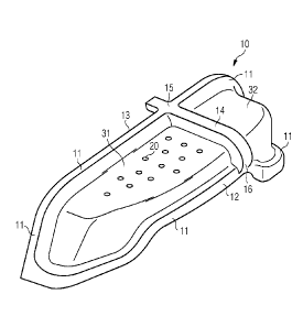
[0048] Figure 1 is a schematic diagram of an exemplary blade 1 of a rotor
of a
turbomachine, such as a gas turbine engine. The blade 1 includes an aerofoil
portion 2 and the
CA 03034743 2019-02-22
=
85024445
11
root portion 3. The aerofoil portion 2 projects from the root portion 3 in a
radial direction as
depicted, wherein the radial direction means a direction perpendicular to the
rotation axis of
the rotor.
[0049] The blade 1 is attached to a rotor disc (not shown) of the
rotor in such a way
that the root portion 3 of the blade 1 is connected to the rotor disc, whereas
the aerofoil
portion 2 is located at a radial outermost position. The aerofoil portion 2
has an outer surface
including a pressure side 6, also called pressure surface, and a suction side
7, also called
suction surface. The pressure side 6 and the suction side 7 are joined
together along an
upstream leading edge 4 and a downstream trailing edge 5, wherein the leading
edge 4 and the
trailing edge 5 are spaced axially from each other, as depicted in figure 1.
"Leading" and
"trailing" is used as a terminology in respect of the fluid flow of the main
working fluid as
indicated by an arrow 60.
[0050] A further element of the blade 1 is a platform 9 which is
formed at an upper
portion of the root portion 3 and in between the root portion 3 and the
aerofoil portion 2.
Thus, the aerofoil portion 2 is connected to the platform 9 and extends in the
radial direction
outwards from the platfomi 9.
[0051] The terminology of "leading" and "trailing" can also be used
for the platform 9,
so that the leading edge 4 of the platform 9 is the region which connects to
the leading edge 4
of the aerofoil 2. The platform 9 can also be distinguished between pressure
side platform and
a suction side platform corresponding to the pressure side 6 of the aerofoil
and the suction
side 7 of the aerofoil 2.
[0052] According to figure 1, more cooling holes 8 may be present on
the pressure
side 6 and/or the suction side 7 of the blade 1 or further cooling holes could
be located at the
leading edge region 4 of the aerofoil 2. These cooling holes could be used for
film cooling of
the blade 1.
[0053] Also the platform 9 could be equipped with film cooling holes.
According to
the figure, a first set of film cooling holes at the pressure side platform is
shown in the figure
CA 03034743 2019-02-22
=
=
85024445
12
with reference to the reference numeral 51. A second set of film cooling holes
at a leading
edge region on the pressure side platform is indicted by reference numeral 52.
[0054] In accordance with the invention, the blade 1 also shows via
broken lines the
platform cooling device 10 disposed underneath the platform 9. The broken
lines show the
location at which platform cooling device 10 will be connected to the blade 1.
This platform
cooling device 10 will be described in the following in more detail.
[0055] The following explanation will be explained in conjunction with
the figures 2
to 5. Figure 2 shows a sectional view of such a blade 1 equipped with a
platform cooling
device 10, wherein the cut for the sectional view is indicated in figure 2 by
the line with the
references A-A. A peripheral or circumferential edge 11 is part of the
platform cooling device
and is configured to be in contact with the platform 9 of the blade 1, as
shown in figure 2.
The circumferential edge 11 defines the farmost border of the platform cooling
device 10. It
encircles or surrounds the platform cooling device 10.
[0056] The contact points or contact ranges to the platform 9 is
indicated in figure 2 as
first edge section 33, which defines a connection to the platform 9, and by a
second edge
section 34, which defines a connection to the root portion 3 of the blade 1.
The
circumferential edge 11 is in continuous contact with the underside of the
blade 1 and does
not show any gaps.
[0057] Further parts of the platform cooling device 10 are distant to
the surfaces of the
blade 1. These sections are particularly the first surface portion 31 and the
second surface
portion 32 as shown in figure 3. The first surface portion 31 is configured to
form the first
cavity 41, as indicated in figure 5, between the platform cooling device 10
and the platform 9.
The second surface portion 32 is configured to form a second cavity 42 between
the platform
cooling device 10 and the platform 9. The first cavity 41 and the second
cavity 42 are
specifically separated by a barrier 14 which is highlighted in figure 3. The
barrier 14 is also
configured, like the circumferential edge 11, to be in contact with the
platform 9. The barrier
14 connects or interlinks two sections 15, 16 of the edge 11, i.e. the barrier
14 is a wall
CA 03034743 2019-02-22
85024445
13
arranged between section 15 and section 16. This connection ¨ i.e. the shape
of the barrier 14
- may be straight or curved. In an embodiment of the invention the barrier 14
is free of
connecting holes between the first cavity 41 and the second cavity 42.
[0058] According to the invention, the two cavities 41, 42 are provided
with different
cooling functionality. The first surface portion 31 comprises a plurality of
impingement holes
20 configured to impinge onto the platform 9 during operation of the gas
turbine engine. The
second surface portion 32, as depicted in figure 3, has specifically no
impingement holes at all
on its surface. Alternatively, but not shown in the figures, impingement holes
may be present
on the second surface portion 32 but with a different number of holes and/or
different
diameters size of the holes in comparison to the first surface portion 31.
100591 A first segment 12 of the edge 11 is configured to connect with the
root portion
3 of the blade, as shown in figure 2. Alternatively, you could also say that
the first segment 12
is connected to a neck section of the blade 1 if you consider that underneath
platform 9 a neck
section is present before the root section 3 starts. Furthermore, a second
segment 13 of the
edge 11 is configured to connect with a rear surface 9 of the platform 9.
"Rear" in this respect
means the back surface of the platform 9. In other words, rear means a
direction radially
inwards in the direction of the root of the blade.
[0060] The barrier 14, as shown in figure 3, may be a straight wall and may
be
substantially perpendicular to the first segment 12 and perpendicular to the
second segment 13
of the circumferential edge 11. Particularly, the barrier 14 interconnects a
first section 15 of
the edge 11 and a second section 16 of the edge 11, wherein the first section
15 is part of the
second segment 13 and the second section 16 is part of the first segment 12 of
the edge 11.
[0061] The barrier 14 may also have a different shape. Furhter the barrier
14 may have
a different angle in respect of the edge 11 than shown in the figure. The main
function of the
barrier 14 is to separate two cavities from another. Depending on the
temperature distribution
on the platform, it may be advantageous to have a barrier angled in a degree
between 45 and
CA 03034743 2019-02-22
85024445
14
90 degrees in comparison to the edge 11. The barrier may also be curved to
adapt to local
temperature profiles.
[0062] The platform cooling device 10 will be placed in a cavity underneath
the
platform 9 as specifically shown in figures 1, 4, and 5. The connection is
advantageously
fixed, for example by brazing, so that the two components are fixedly
connected to another.
[0063] The previously mentioned first cavity 41 and second cavity 42 are
specifically
shown in figure 5, which shows a see-through picture of the blade 1 including
the platform
cooling device 10. With reference to figure 5 and figure 4, the first cavity
41 extends via a
central region or section 72 and a trailing edge 73 of the platform 9. The
second cavity 42 is
extending in the leading edge region 71 of the platform 9. Therefore, these
two cavities can be
adapted to fulfill the cooling needs along the platform length.
[0064] The first cavity 41 and the second cavity 42 are in fluid connection
with further
passages and cavities within the blade and/or surrounding components. A
cooling fluid supply
passage 17 may be present in the blade 1 to provide cooling fluid to the
second cavity 42. This
cooling fluid supply passage 17 may provide a connection from an aerofoil
supply passage 28
(shown in figure 2) and the second cavity 42. Furthermore, according to figure
5, the provided
cooling fluid to the second cavity 42 is exhausted via second film cooling
holes 52 (which
have been indicated in figure 1 and figure 5). These film cooling holes 52
correspond to an at
least one second passage piercing the platform 9 to exhaust the cooling fluid
from the second
cavity 42. The second film cooling holes 52 are specifically located at the
leading edge
portion 4' of the platform 9
[0065] The first cavity 41 may be supplied by cooling fluid via the
impingement holes
20 in the first surface region 31. The cooling fluid for the impingement holes
20 is provided
from a disc cavity (highlighted as 90 in figure 4) and a cavity between two
adjacent rotor
blades as indicated by reference numeral 27' in figure 5. Some of the cooling
air collected in
the first cavity 41 will be exhausted via first film cooling holes 51 as the
at least one first
passage. The first film cooling holes 51 are depicted in figure 1 and figure 5
and exhaust the
CA 03034743 2019-02-22
85024445
cooling air specifically into trailing edge section of the platform 9. A
further cooling fluid
release passage 18 may be present, as shown in figure 2 and figure 5, to
release cooling fluid
from the first cavity 41 into an aerofoil supply passage 28 for cooling fluid
which is supposed
to be provided to an aerofoil cooling system 29. The aerofoil supply passage
28, as shown in
figure 2 typically connects two cooling fluid core channels as part of the
hollow blade core
and is part of the aerofoil cooling system. The cooling fluid flow in parts is
shown by arrows
in figures 2 and 5 with the reference numerals 27 and 27.
[0066] The inventive platform cooling device 10 provides a screen for the
underneath
side of the blade 1 to provide specific cooling functionality to the blade
platform. The
platform cooling device 10 comprises an impingement hole section at the first
cavity 41 and a
different section without impinging at the second cavity 42. Therefore,
specific cooling
requirements can be met along the length of the platform 9.
100671 The invention specifically is advantageous as the cooling of the
pressure side
platform of a blade can be improved. Furthermore, as the platform cooling
device 10 is a
piece that can be equipped with different cooling functions, different engines
experiencing
different temperature profiles can be equipped with different and specifically
adjusted
platform cooling devices 10. The platform cooling device 10 can also be used
just for testing
different cooling functions before providing them in a final blade design.
Besides, as the blade
cooling device 10 and the blade 1 are separate components, they are easy to
manufacture and
more complex cooling structures can be enclosed in the combined component.
[0068] As a further benefit, the blade 1 and the platform cooling device 10
can be
manufactured by using different technologies. For example, the platform
cooling device 10
could be manufactured by laser sintering. Furthermore, different material
could be used for
the blade 1 and the platform cooling device 10. Therefore, the overall costs
could be reduced
for the blade and also materials could be used that withstand higher
temperatures.
CA 03034743 2019-02-22
85024445
16
[0069] The platform cooling device 10 could be brazed or fastened in
another way to
the blade 1. Additionally, the laser sintering could be performed directly
onto the blade 1 so
that the two components connect to a single entity.
[0070] The platform cooling device 10 may also have an extension 80, as
shown in
figure 5, which may be an outwards extension of the barrier 14 to allow easier
manufacturing
and assembly of the two components, i.e. the blade and the platform cooling
device.
[0071] The invention is particularly advantageous as thermal damages could
be
reduced even though higher temperatures could be used during operation of the
gas turbine
engine. Particularly, the pressure side platform could be cooled in a highly
controlled way.
[0072] Furthermore, the invention is advantageous as the platform cooling
device 10
can be equipped even for existing blades that do not have this feature
available yet.