Note: Descriptions are shown in the official language in which they were submitted.
CA 03035155 2019-02-26
WO 2018/104975
PCT/IT2017/000274
APPARATUS FOR SELECTIVELY SHARING THE POWER OF A
MULTIDRIVE UNIT VEHICLE
Technical field
This invention relates to an apparatus for selectively sharing, towards
separate users,
the power of a multi-drive unit vehicle.
Background Art
As is known, many motor vehicles of the current build type are equipped with
many
services that are auxiliary and accessory to the driving of vehicle movement,
that is
to say, not assigned to actual propulsion of the vehicle.
Some of those services also require levels of power that are considerable and,
in the
case of electric drive units, are even difficult to supply, since the electric
voltages
involved are low.
Consider, for example, the vehicle air conditioning system, where the maximum
power required is often greater than 3kW; or the power steering system, in
which the
power used is approximately I Kw; or even the compressor of the brake and
suspen-
sion circuit which, in large capacity vehicles may require power levels even
greater
than 5Kw. Similar conditions occur for the power take offs of commercial or
special
vehicles, which may use levels of power comparable to or, at times, greater
than the
levels of power required for driving vehicle movement.
In a traditional vehicle, all of these services draw the power necessary for
their oper-
ation directly from the drive unit that propels the vehicle, or from an
auxiliary drive
unit or power supply system dedicated specifically to the service.
In the former case, a first disadvantage is the fact that operation of the
auxiliary ser-
vices is linked to the variation in the speed (revolutions) of the drive unit
that drives
vehicle movement, which, varying constantly due to the variable requirements
of the
road route, makes the efficiency of the supply of power to secondary service
units
dependent on the instantaneous power actually and residually available. That
is to
say, dependent on the share of the power that is not needed for driving
vehicle
CA 03035155 2019-02-26
WO 2018/104975
PCT/IT2017/000274
movement. Another disadvantage is also the fact that where the drive unit for
driv-
ing vehicle movement is a combustion engine and must be kept running even if
ser-
vices are required while the vehicle is stationary, this results in wasted
power, the
production of polluting emissions and reduced efficiency.
That is obvious, for example, in applications such as the -crane truck" type
where,
once the vehicle has reached the destination, use of the auxiliary service may
even
continue for weeks or months, during which time the drive unit for driving
vehicle
movement must be kept running in order to supply power to the lifting system.
That
even applies if the power needed is several orders of magnitude lower than the
pow-
er output that the drive unit for driving vehicle movement is actually capable
of sup-
plying. Moreover, it should be noticed that this architecture is possible, in
use, only
if the drive unit for driving vehicle movement can be mechanically
disconnected
from the driving wheels.
In the case of a combustion engine that is easily feasible, since by its
nature the sys-
tern requires a mechanical disconnection, due to the fact that the engine
cannot drop
below a minimum number of revolutions without stalling.
A very different condition is encountered in direct electric drive vehicles.
In fact, in these, the disconnection method referred to above may be difficult
to im-
plement, meaning that an alternative solution used is that of installing
motors dedi-
cated specifically to the individual services.
However, whilst on one hand this solution has the advantage of removing the
link
between the motor speeds, on the other hand it disadvantageously requires an
in-
crease in the components necessary, consequently increasing: system
complexity,
weights, costs and overall dimensions.
With regard to that, consider for example vehicles with auxiliary services
whose
power requirements are comparable to the power needed to drive vehicle
movement.
These vehicles would have to be fitted with two motors of comparable
dimensions,
one solely for driving vehicle movement, the other solely for the auxiliary
service.
Moreover, such vehicles would have to be equipped with other motors for
additional
auxiliary services using lower levels of power.
,
CA 03035155 2019-02-26
WO 2018/104975
PCT/IT2017/000274
Disclosure of invention
The technical purpose of this invention is therefore to overcome such
disadvantages.
Accordingly, these results are achieved by means of an apparatus for
selectively
sharing, towards separate users, the power of a multi-drive unit vehicle, made
in
accordance with claim I.
The technical features of the invention, which fulfil the technical purpose,
are
clearly described in the appended claims.
Brief description of drawings
io The advantages of the invention are more apparent in the detailed
description which
follows, with reference to the accompanying drawings which illustrate an
example,
non-limiting embodiment of the invention, in which:
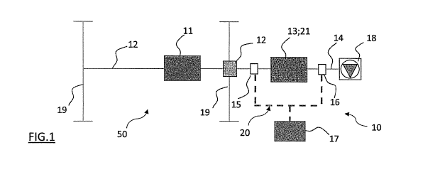
- Figure 1 is an operating block diagram schematically illustrating a motor
vehicle equipped with an apparatus according to the invention;
- Figure 2 is an efficiency curve of an auxiliary service of the vehicle;
- Figure 3 is an efficiency map of a brushless electric motor with surface
magnets advantageously usable in the invention.
Best mode for carrying out the invention
With reference to the figures of the accompanying drawings, in Figure 1 the
numeral
(50) denotes a schematic diagram of a generic, multi-drive unit vehicle that
comprises an apparatus (10) for selectively sharing towards separate users
(19;18)
the total power that can be supplied by the plurality of drive units (11;21).
The apparatus (10) basically comprises a mechanical transmission (12) that
connects
propulsion units (19) of the vehicle (50) to one or more primary drive units
(11); and
a secondary power unit (13) for service units, which is operatively positioned
between the mechanical transmission (12) and one or more service or auxiliary
units
(18) of the vehicle (50).
The apparatus (10) also comprises a first and a second joint (15,16), that are
mounted on the mechanical transmission (12) on either side of the secondary
power
3
CA 03035155 2019-02-26
WO 2018/104975
PCT/IT2017/000274
unit (13) for service units and are switchable by operating suitable control
means
(20).
More particularly, said control means (20) comprise a microprocessor-type
controller (17), operatively interfaced with said joints (15,16), for
selectively
activating the sharing of power between the propulsion units (19) and said one
or
each service unit (18), relative to operation required of the vehicle (50) at
the various
moments of its use.
The primary drive unit (11) may be a combustion engine or an electric motor.
The secondary power unit (13) for service units comprises one or more
secondary
to drive units (21), which are electric motors or combustion engines, for
generating
power to be sent to one or more of said service units (18).
The microprocessor-type controller (17) is adapted for managing the sharing of
power towards the propulsion units (19) in a highly flexible way. In fact, the
sharing
may be performed, for example, by giving prevalent, priority or exclusive
status to
requests for driving (propelling) power that come from said propulsion units
(19),
made necessary by the requirements of driving the movement of the vehicle
(50).
Similarly, the microprocessor-type controller (17) is adapted for managing the
sharing of power towards said one or each service unit (18), depending on a
variety
of different correlations resulting, for example, between requests for driving
power
for the propulsion units (19) and efficiency curves (22) characteristic of
said primary
drive units (11) and/or secondary drive units (21) relative to which optimum
management can be achieved both in terms of propulsion performance, and
accessory services of the vehicle (50).
Several examples provided below give a clearer description of some features
and
advantages of the invention.
Imagine that the primary drive unit (11), for driving vehicle movement, is an
electric
motor with a maximum power of 30kW and the secondary power unit (13) is a
secondary electric motor (21), with a maximum power of 10kW, dedicated for
example to supplying power to a refrigerating compressor with efficiency shown
in
Figure 2 by the efficiency curve (22).
4
,
CA 03035155 2019-02-26
WO 2018/104975
PCT/IT2017/000274
If the joint (15) is disconnected, the two electric motors (11,21) are
independent of
each other and the secondary power unit (13) can supply its power for
compressor
unit maximum efficiency. That is to say, it reaches 4,000 rpm, irrespective of
the
speed and conditions of the vehicle (50). Therefore, with this configuration,
the
auxiliary unit (18), that is to say, the compressor circuit, operates with
maximum
efficiency levels that are definitely much higher than a circuit having the
same
features that is connected directly to the transmission (12) used for driving
vehicle
movement, that is to say, with revolutions per minute (rpm) variable depending
on
the speed required of the vehicle (50) in the various propulsion conditions.
It should be noticed that with this configuration, when the vehicle is
stationary, the
speed of the primary drive unit (11), used for driving vehicle movement, can
be
brought down to 0 (rpm), thereby interrupting all power consumption by the
primary
drive unit (11), since all of the power required by the auxiliary services can
be
supplied by the secondary power unit (13) for service units. Every time that
operation of the refrigerating unit is not necessary (for example, after it
has reached
the temperature set), the apparatus (10) will interrupt the supply of power to
the
secondary power unit (13) for service units, which will be able to stop,
thereby
interrupting power consumption.
Therefore, in this configuration, the apparatus (10) is able to maximise the
efficiency
of the auxiliary services, but not that of the system used for driving vehicle
movement.
Now imagine that the vehicle (50) - in a different example situation - is
travelling at
a constant speed, with a torque requirement for the drive unit that drives
vehicle
movement equal to 50Nm at 2,500 rpm. Considering the drive unit efficiency map
(Figure 3, operating point 1), the drive unit for driving vehicle movement
operates
with 81% efficiency. In this condition, this invention allows connection of
the
secondary power unit (13) for service units to the system for driving vehicle
movement. This shifts the operating point of the total drive units driving
vehicle
movement to a higher efficiency value, in this example equal to 86%, therefore
recovering 5% efficiency from the system for driving vehicle movement. If the
5
CA 03035155 2019-02-26
WO 2018/104975
PCT/IT2017/000274
service unit (18) constituted of the auxiliary devices does not require power,
it is
possible to disconnect the joint (16), so that there is no type of power draw
on the
services side. Otherwise, the loss of efficiency in the case considered, due
to the
variation of the operating point of the system of auxiliary services, will be
3%.
The microprocessor-type electronic control device (17) may, therefore, manage
distribution of the power of the secondary power unit's drive unit (21),
dynamically
evaluating the vehicle (50) requirements of power for driving vehicle movement
and
for services, the efficiency maps of the electric motors (11,21) and the
efficiency
curves or maps of the auxiliary devices, in order to always obtain from the
apparatus
(10) conditions allowing the vehicle (50) to operate in any condition at the
maximum efficiency point achievable.
Another advantage of the invention is that it allows use of the sum of the
powers of
its drive units (11,21), either for driving vehicle movement, or for the
services. In
that case, for the vehicle (50) described in the previous example and
illustrated in
Figure 1, obviously the vehicle (50) with a 30kW drive unit (11) for driving
vehicle
movement is able to supply power up to a maximum of 40kW either for the
auxiliary
services, or for driving vehicle movement.
The invention achieves the preset aims and provides further advantages in
terms of
safety, since at least two drive units (11;21) are available for driving
vehicle
movement or for the services, and if one develops a fault, the other can help
the
vehicle (50) in order to put the vehicle (50) in safer conditions.
The invention described above, which achieves the preset aims, is susceptible
of ev-
ident industrial application. It may also be modified and adapted in several
ways
without thereby departing from the scope of the following claims. With regard
to
that, it should be noticed that electric generators may be used as alternative
embod-
iments of the service unit (18) and/or of the secondary power unit (13) for
service
units. Moreover, all details of the invention may be substituted by
technically equiv-
alent elements.
6