Note: Descriptions are shown in the official language in which they were submitted.
CA 03035204 2019-02-26
WO 2018/044417
PCT/US2017/042851
-1-
Description
SPLINED IDLER FOR SCALLOP RESISTANCE
Technical Field
The present disclosure relates to an idler wheel that is used as a
part of a track chain assembly attached to the undercarriage of track-type
vehicles
used for off-road operations such as those that use endless tracks for moving
on
the ground. Specifically, the present disclosure relates to an idler wheel
that is
configured to reduce the scalloping of track links that may lead to track
chain and
machine maintenance.
Background
In many current applications, track links that are part of track
chains develop a scallop pattern on their top or rail surfaces that contact
various
drive and support members of the undercarriage including rollers and idler
wheels. The scallops look like depressions on the rail surface of the links.
These
depressions are caused by contact of the rollers and the idler in a consistent
place
on the link as the track chain continuously revolves around on the drive
sprocket,
idler wheels and the rollers. In many cases, the track links have rails with a
center portion that is thicker in a direction parallel to the axis of rotation
of the
idler wheel as compared to a similar thickness of the end portions.
Consequently,
an idler wheel and roller tend to contact the center portion more completely
and
less completely at the ends where that portion of the link is not overlapped
by an
adjacent link. This leads a deeper more complete scallop, often referred to as
a
primary scallop, being formed at the center of the rail portion of the track
link,
while a secondary scallop that this less complete may be formed at the end
portions of the rail of the track link. These secondary scallops are often
positioned at the 1/4 position of the rail, measured from the front of the
rail, and at
CA 03035204 2019-02-26
WO 2018/044417
PCT/US2017/042851
-2-
the 3/4 position of the rail, also measured from the front of the rail, while
the
primary scallop would be located between the 1/4 and 3/4 positions.
Scalloped track links may lead to various problems. For example,
over time, the manner in which the idler wheel and rollers contact the links
may
become uneven, causing vibration that may lead to an uncomfortable ride. Also,
this may lead to maintenance issues for the undercarriage and the machine.
Summary
An idler wheel for use with a track chain of a vehicle that includes
a plurality of track pins and bushings is provided. The idler wheel comprises
a
main body that includes a generally cylindrical configuration defining an axis
of
rotation, a circumferential direction and a radial direction, the main body
including a central portion disposed along the axis of rotation defining an
axial
extremity of the radial portion, and at least a first outside portion disposed
along
the axis of rotation that includes an undulating circumferential perimeter
with a
plurality of apexes and valleys.
An undercarriage for use with a vehicle that includes an endless
track drive is provided. The undercarriage comprises a track chain including a
plurality of track pins and track bushings disposed about the track pins, and
a
plurality of track links that are connected to each other by either a track
pin or a
track bushing, wherein at least one track link comprises defines a plurality
of
apertures for receiving a track pin or bushing. The undercarriage may further
comprise an idler wheel including a main body that includes a generally
cylindrical configuration defining an axis of rotation, a circumferential
direction
and a radial direction, the main body including a central portion disposed
along
the axis of rotation defining a radial extremity of the central portion, and
at least a
first outside portion disposed along the axis of rotation that includes an
undulating circumferential perimeter with a plurality of apexes and valleys.
CA 03035204 2019-02-26
WO 2018/044417
PCT/US2017/042851
-3-
Brief Description of the Drawings
The accompanying drawings, which are incorporated in and
constitute a part of this specification, illustrate several embodiments of the
disclosure and together with the description, serve to explain the principles
of the
disclosure. In the drawings:
FIG. 1 is a side enlarged view of an idler wheel according to an
embodiment of the present disclosure used with a track chain assembly as part
of
a machine undercarriage.
FIG. 2 is a side view of the idler wheel of FIG. 1 shown in
isolation from the machine undercarriage.
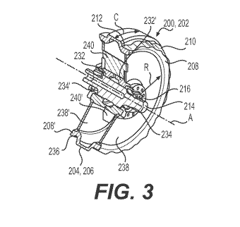
FIG. 3 is a perspective view of the idler wheel of FIG. 2 shown in
partial cross-section to show various components of the rotating connection of
the
idler wheel to the axle.
FIG. 4 is a front view of a track chain assembly and idler wheel
according to an embodiment of the present disclosure, showing how the idler
wheel contacts the top rails of the track links.
FIG. 5 is a simplified schematic view of another embodiment of
an idler wheel according to the present disclosure.
FIG. 6 is an enlarged front view of an idler wheel according to an
embodiment of the present disclosure to show more clearly the dimensions of
the
undulations that may be employed.
FIG. 7 is a side view of a tractor using an endless track chain that
may use an idler wheel in accordance with various embodiments of the present
disclosure.
FIG. 8 is a side view of an endless track that is similar to that
disclosed in FIG. 7 but is isolated from the tractor, illustrating more
clearly an in-
line configuration of endless track.
FIG. 9 is a front view of an endless track similar to that shown in
FIG. 8 except that is uses an elevated drive sprocket.
CA 03035204 2019-02-26
WO 2018/044417
PCT/US2017/042851
-4-
FIG. 10 is an enlarged front view of a pair of track links that are
joined together by a track pin and bushing in a manner that is similar to the
tracks
illustrated in FIGS. 8 and 9.
FIG. 11 is a top view of the track links, bushing and track pin of
FIG. 10. The track shoes are removed for extra clarity.
FIG. 12 is a perspective sectional view of track links, a bushing
and track pin that is similar to that shown in FIG. 11.
FIG. 13 is a plan sectional view of track links, bushing and track
pin similar to that shown in FIG. 12, where the track pin is of solid
construction,
lacking a central oil groove that runs along its cylindrical axis.
Detailed Description
Reference will now be made in detail to embodiments of the
disclosure, examples of which are illustrated in the accompanying drawings.
Wherever possible, the same reference numbers will be used throughout the
drawings to refer to the same or like parts. In some cases, a reference number
will be indicated in this specification and the drawings will show the
reference
number followed by a letter for example, 100a, 100b etc. It is to be
understood
that the use of letters immediately after a reference number indicates that
these
features are similarly shaped and have similar function as is often the case
when
geometry is mirrored about a plane of symmetry. For ease of explanation in
this
specification, letters will often not be included herein but may be shown in
the
drawings to indicate duplications of features discussed within this written
specification.
Various embodiments of the present disclosure include an idler
wheel that is configured to reduce the scalloping of track links. This may be
accomplished in a number of ways such as by providing an undulating contact
surface on the idler wheel that contacts the track link in a different
position most
the time the idler wheel contacts that particular track link. To this end, the
idler
wheel may have an undulating profile that is consistent or varying about the
CA 03035204 2019-02-26
WO 2018/044417
PCT/US2017/042851
-5-
circumferential perimeter of the idler wheel, that has an odd number of
contacting
portions about the circumference of the idler wheel, and/or the effective
tangential circular distance about the circumference of the undulating profile
may
not be evenly divisible into the linear length of the track chain that the
idler wheel
is intended to contact, etc.
FIGS. 1 thru 3 illustrate an embodiment of an idler wheel 200 and
undercarriage system 300 according to the present disclosure. The
undercarriage
system 300 of FIGS. 1 and 3 is directed to a track chain assembly 302 using a
plurality of straight track links 304, so called, as its cross-sectional area
does not
vary from one end to the other. It is to be understood that the configuration
of the
track link for any embodiment discussed herein may be varied as needed or
desired. Any embodiment of a track link described herein may be used as part
of
a track chain assembly of a vehicle 100 that includes a plurality of track
pins and
bushings. This will be described in further detail later herein.
Starting with FIGS. 1 and 3, an undercarriage 300 for use with a
vehicle that includes an endless track drive is shown. The undercarriage 300
comprises a track chain assembly 302 including a plurality of track pins 306
and
track bushings 308 disposed about the track pins 306, and a plurality of track
links 304 that are connected to each other by either a track pin 306 or a
track
bushing 308, wherein at least one track link 304 comprises defines a plurality
of
apertures for receiving a track pin or bushing.
Looking at FIGS. 1-3, a rear idler wheel 200 is also shown that
includes a main body 202 that includes a generally cylindrical configuration
defining an axis of rotation A, a circumferential direction C and a radial
direction
R. The main body 202 includes a central portion 204 disposed along the axis of
rotation A defining radial extremity 206 of the central portion 204, and at
least a
first outside portion 208 disposed along the axis of rotation A that includes
an
undulating circumferential perimeter 210. The radial extremity 206 of the
central
CA 03035204 2019-02-26
WO 2018/044417
PCT/US2017/042851
-6-
portion 204 may nor may not be configured to make contact with the bushings
308 of the track chain assembly 302.
In addition to the idler wheel 200 being shown to have a rotating
attachment to the frame 314 of the undercarriage 300, a support roller 310 and
a
drive sprocket 312 are also shown to have rotating attachments to the frame
314,
represented by rotation axes C and B respectively in FIG. 1. As also shown in
FIG. 1, an elevated configuration (drive sprocket is elevated) of an
undercarriage
system 300 is shown but it is contemplated that other embodiments could use an
inline configuration as will be described later herein.
For this embodiment as shown in FIGS. 2 and 3, the undulating
circumferential perimeter 210 defines a radial extremity 212 of the first
outside
portion 208 of the idler wheel 200, wherein the radial extremity 206 of the
central
portion 204 is further away from the axis of rotation A than the radial
extremity
212 of the first outside portion 208 along the radial direction R. This may
not be
the case in other embodiments. Similarly, the central portion 204 may include
an
axial offset (not shown in FIGS. 2 and 3) near its radial extremity 206 but
this
may not be the case in other embodiments.
FIG. 2 shows a hub 216 that may be used to attach the idler wheel
200 to the axle of the machine. The axle 214 and other parts of the idler
wheel
assembly 200 are shown in FIG. 3. The axle 214 is surrounded by bearings 232.
Rotating face seals 234 are also employed as is known in the art to hold
lubrication such as oil in the rotating joint. The rim portion 236 of the
idler
wheel assembly 200 is connected to the hub 216 via a pair of annular shaped
plates 238 that are supported and interconnected by spoke members 240
contained within the idler wheel assembly 200. Idler wheels of other
configurations including having unitary construction are also contemplated to
be
within the scope of the present disclosure.
As can be seen best in FIG. 3, the main body 202 includes a
second outside portion 208' that is positioned on the axially opposite side of
the
CA 03035204 2019-02-26
WO 2018/044417
PCT/US2017/042851
-7-
central portion 204 compared to the first outside portion 208, wherein the
second
outside portion 208' is similarly configured as the first outside portion 208.
For
this embodiment, the idler wheel 200 is symmetrical about an axial plane AP
centered on the axis of rotation A of the idler wheel 200 (see FIG. 4). Other
embodiments may be asymmetrical.
As best seen in FIG. 2, the undulating circumferential perimeter
210 of the idler wheel 200 includes a plurality of apexes 218 and valleys 220.
An
apex or valley is that portion of the perimeter 210 where the inflection of
the
perimeter changes, that is to say, a tangent to the perimeter changes its
slope from
a positive slope to a negative slope, or vice versa. A curve 222 may be
defined
about the circumferential perimeter 210 of the first outer 208 portion that is
tangent to every apex 218 of the undulating circumferential perimeter 210. As
shown, the curve 222 is a circle but this may not be true for other
embodiments.
As best understood by referring to FIGS. 1, 2, and 7-9, the track
chain assembly 302 defines a track chain length L302 and the circle 222
defines a
circumferential length L222, and the track chain length L302 divided by the
circumferential length L222 of the circle yields a non-integer value in some
embodiments. This helps to ensure that the apex 218 of the undulating
perimeter
210 will contact a different spot most the time the idler wheel 200 contacts a
particular link 304. This helps reduce the likelihood of scalloping the link
304.
Focusing now on FIG. 2, each curve segment 224 of the
undulating perimeter 210 includes an arcuate shape. It is contemplated that in
some embodiments that the curve segment 224 could be a concavely shaped
radius, as would be the case for a valley 220, and a convexly shaped radius,
as
would be the case for an apex 218. These radii could transition from one to
the
other directly, or indirectly, as would be the case if a straight or flat
curve joined
them together. Any suitable undulating perimeter may be used in other
embodiments including zig-zagged with rounded peaks, squared with rounded
corners, sinusoidal, polynomial such as a spline, involute, etc.
CA 03035204 2019-02-26
WO 2018/044417
PCT/US2017/042851
-8-
In yet other embodiments, the undulating circumferential
perimeter 210 may include an odd number of apexes 218 that helps to ensure
that
an apex 218 contacts a different portion of a particular track link 304 most
the
time as the track link 304 revolves around the undercarriage 300 and contacts
the
idler wheel 200 once more. Also as best seen in FIG. 6, the linear
circumferential
distance L218 from one apex 218 to the next apex 218' may be the same about
the entire circumferential perimeter 210 of the first outer portion 208 of the
idler
wheel 200. In such a case or in other embodiments, the undulating
circumferential perimeter 210 may comprise a circular array 226 of repeating
geometrical apexes 218 and valleys 220 about the axis of rotation A. This
consistency may not be present in other embodiments. The dimensions of the
undulating perimeter 210 may be approximately measured like a sinusoidal
waveform or the like, having a radial amplitude RA and a half wavelength HW.
It is contemplated that the amplitude RA may range from 5-10 mm and that the
half wavelength HW may range from 10-160 mm in various embodiments.
FIG. 4 depicts another version of the idler wheel 200' with outside
flanges 242. As shown, the idler wheel 200' contacts the rails 316 of the
track
links 304. For this embodiment, the flanges 242 are positioned closely to the
outside of the rails 316 of the links 304, helping to prevent lateral movement
of
the track chain assembly 302 with respect to the idler wheel 200'. The central
portion 204 of the idler wheel 200' does not contact the bushing 308 and the
outer
portions of the idler wheel 200 have undulating circumferential perimeters 210
in
a manner consistent with what has been described with reference to FIGS. 1-3.
Looking at FIG. 5, the plurality of track links 304 may include a
rail portion 316 that is configured to complimentary mate with the
circumferentially undulating perimeter 210' of the idler wheel 200". This may
involve the provision of an undulating surface 318 on the rail portion 316 of
the
link 304. For the embodiment depicted in FIG. 5, the undulating
circumferential
perimeter 210' is interrupted along the circumferential direction C of the
idler
CA 03035204 2019-02-26
WO 2018/044417
PCT/US2017/042851
-9-
wheel 200'. That is to say, there are gaps 228 between the undulations. Each
portion of the idler wheel 200' that forms an apex 218 may be referred to as a
spline 230. As shown in FIGS. 1 and 2, the undulations may be continuous or
uninterrupted in other embodiments. The rail surface of other track links may
be
flat as illustrated in FIGS. 1 and 4.
Industrial Applicability
In practice, a track chain assembly and/or an idler wheel may be
sold, manufactured, bought etc. and attached to the machine in the aftermarket
or
original equipment scenarios. That is to say, the machine may be sold with the
track chain assembly and idler wheel according to embodiments described herein
or the machine may be retrofitted, repaired, refurbished to use any of the
embodiments discussed herein. The idler wheel may be machined from a single
piece of material to provide a suitable undulating profile that is intended to
contact the links of the track chain assembly or the idler wheel may include
an
assembly of multiple components. In other embodiments, the splines may be
added to the idler wheel by fastening, welding, etc. Continuous undulating
profiles may also be added as one piece or in segments to an idler wheel, etc.
FIG. 7 illustrates a track-type tractor 100 employing a pair of
endless track chain assemblies 102 (one shown) of this invention thereon.
Although the track assembly is particularly adapted for use on a tractor, it
should
be understood that the track assembly will find application to other vehicles,
such
as track-type excavators or any other type of off-road vehicle or machinery.
In the
tractor application illustrated in FIG. 7, each track chain assembly 102 is
mounted in a conventional manner on a drive sprocket 104, an idler 106, a
plurality of longitudinally spaced track rollers 108, and a pair of upper
guide or
carrier rollers 110, when needed. The idler wheel may be substituted with
idler
wheel 200, 200', etc. as described earlier herein. Also, the links of the
track
chain assembly 102 of FIG. 7 are shown to be offset links instead of straight
links
as shown in FIG. 1.
CA 03035204 2019-02-26
WO 2018/044417
PCT/US2017/042851
-10-
Referring to FIGS. 8 and 9, a track assembly 102 comprises a
plurality of track shoes 112 which are pivotally interconnected by an
articulated
link assembly 114. Link assembly 114 is disposed intermediate the widths of
track shoes 112 and includes a plurality of pairs of links, pivotally
interconnected
together by standard pin and bushing assemblies 118. The teeth 120 of drive
sprocket 104 engage the bushings of pin and bushing assemblies 118 to drive
track assembly 102 in a conventional manner with the track assemblies being
guided by idler 106 and rollers 108 and 110 which engage upper rail portions
of
links. The main difference between the configurations of the track assembly of
FIGS. 8 and 9 is that FIG. 8 is an inline configuration, so called as the
drive
sprocket is in-line with the front idler wheel forming a substantially ovular
path
for the track, while FIG. 9 shows an elevated configuration, so called as the
drive
sprocket is vertically above the lower idler wheels forming a substantially
triangular path for the track. Again, idler wheels 106 in FIGS. 8 and 9 may be
substituted with idler wheels 200, 200', 200" etc. as described earlier
herein.
With continued reference to FIGS. 8 and 9, the lower rollers are
often called track rollers 108 as they support the weight of the vehicle and
transfer it to the track and then to the ground while the upper rollers are
often
called carrier rollers 110 as they only carry or support the track, limiting
or
sometimes modifying the catenary hang of the track. The drive sprockets 104
have segments 122 with drive teeth 122 connected to them or integrally formed
therewith that mesh with the links in the track chain assembly 102, powering
movement of the track, and thus the vehicle. The shoes 112 include provide
movable platforms that engage the ground and include ribs or grousers 124 that
penetrate the ground, providing traction. The idler wheels 106 lack teeth but
ride
between the links (see G in FIG. 5) and on top of the rails of the links,
limiting
side to side movement of the track. Similarly, the rollers 108, 110 provide a
conduit for the transfer of weight, and in many cases, provide a way to adjust
the
CA 03035204 2019-02-26
WO 2018/044417
PCT/US2017/042851
-11-
tension in the track. The rollers 108, 110 also ride between the links 116 and
on
top of the rails of the links, limiting side to side movement of the track.
Turning now to FIGS. 10 and 11, they show an example of a link
assembly 114 that includes a pair of track links that are joined together by a
track
pin and bushing assembly 118 in a manner consistent with the tracks
illustrated in
FIGS. 8 and 9. The track pin and bushing assembly 118 form a joint that
includes a
cylindrical pin 126, and a rotatable tubular bushing 128. The pin 126 has
opposite
end portions 132 (best seen in FIG. 11), each of which is pressed and non-
rotatably
mounted into a respective one of the bore 134 formed by a protruding boss 136
of
the outboard end collars 138 of each link 116 in a link set 114. The pin and
bushing assembly 118 further includes a method and device for mechanically
interlocking the pin 126 within such bores 134 to prevent any axial movement
of
the links 116 along a longitudinal or cylindrical axis 140 of the pin 126.
Other types of methods for mechanically interlocking the pin to
the links that are known or that will be devised in the art may be employed.
One
mechanically interlocking method comprises a circumferentially disposed,
generally arcuately shaped groove formed about each of the end portions of the
pin and at least one mechanically formed nodule which protrudes radially
inwardly from each of the bores into a respective one of the grooves. The
mechanically formed nodules are preferably formed by using a punch device.
Preferably, a pair of such punch devices are located perpendicular to the pin
axis
on each of the flats provided on the pin boss. The application of a sufficient
force
of the punch devices will result in the extrusion of the boss metal into the
groove.
Other methods for achieving this are also available and may be used.
Referring to FIG. 12, there is shown a portion of an undercarriage
for a track-type machine that uses a track chain assembly 102 and link
assembly
114 that are similar to those described thus far herein. The tubular bushing
128 is
provided with a pin bore 142 which is of a size sufficient to freely rotatably
mount the bushing 128 about the pin 126. Bushing 128 has a pair of opposite
end
CA 03035204 2019-02-26
WO 2018/044417
PCT/US2017/042851
-12-
faces 144 and is of a size to extend between and to freely rotatable relative
to the
inboard end collars 146.
As shown in FIG. 12, each link assembly includes inboard links
and outboard links. Inboard links and outboard links may be coupled together
with a plurality of additional inboard and outboard links (not shown), to form
an
endless chain extending about a conventional drive mechanism including one or
more track idlers and a drive sprocket. This may be used in a variety of track-
type
machines, such as a track-type tractor, tracked excavator, tracked loader, or
the
like. One practical implementation of the teachings set forth herein is
contemplated to be in track-type tractors used in particularly harsh field
conditions, such as mines and landfills.
The track pin 126 may be press fit with outboard links. In one
embodiment, retention rings 148 or some other mechanism for positive pin
retention may be coupled with pin 126 to enhance the strength of the coupling
with outboard links 200, 200'. In the embodiment shown, inboard links and
outboard links include S-shaped or offset links, however the present
disclosure is
not limited in this regard and straight link track might also be used. During
operation as already discussed, one or more track idlers and a drive sprocket
may
engage with the bushing 128 to guide and provide power to the track in a
conventional manner. As will be familiar to those skilled in the art, some
structure for lubricating surfaces which move against one another within the
track
assembly may be desirable. To this end, the pin 126 may include an oil passage
150 which serves as an oil reservoir for supplying oil to desired locations
within
track segment.
During track assembly at the factory or during track repair or
servicing, lubricating oil may be supplied into passage 150, and the oil
passage
may be plugged to seal the lubricating oil therein. A set of seals 152 may
also be
provided, which fluidly seal between outboard links and bushing 128 to retain
oil
within the link assembly 114. The link assembly 114 also includes a set of
thrust
CA 03035204 2019-02-26
WO 2018/044417
PCT/US2017/042851
-13-
rings 154, each positioned between the bushing 128 and one of outboard links
116'. Thrust rings 154 can react to thrust loads through the link assembly
114,
and may be configured to prevent compressive forces on seals 152 which can
otherwise impart a tendency for seals to fail. Each of thrust rings 154 may be
uniquely configured to provide a robust mechanism for reacting thrust loads,
but
also facilitate the transfer into and maintaining of oil within a region of
the link
assembly 114 defined between bushing 128 and outboard links, and also between
each seal 152 and the pin 126. It should be noted that the oil passage is
shown in
dotted lines, indicating that in certain embodiments, it may not be present,
such
as will now be described.
FIG. 13 shows another track link assembly 114 that is known in
the art that lacks an oil passage or other void that surrounds the
longitudinal axis
of the pin. This link assembly 114 includes a seal assembly 156 that includes
first and second seal members 158, 160 that provide sealing between the
inboard
end collars 146 of the outboard link and the bushing 128. Each of the seal
assembly 156 is disposed within each of the counterbores 162 between the
shoulder 164 of the counterbore and the adjacent outer end face 144 of the
bushing 128 and in sealing engagement against the outer end face 144. These
type of seals are often referred to as rotating face seals as they allow the
bushing
to rotate relative to the pin 126 and outboard link while still keeping
lubrication
from leaking. Also, thrust rings are provided between the pin and seal
assembly
for reasons already explained above. The pin includes regions that absorb
loads
from the links either directly or indirectly through the bushing.
Specifically,
region 166 is in contact with the outboard link 116' while region 168 is in
contact
with the bushing 128 directly underneath the inboard link.
It will be apparent to those skilled in the art that various
modifications and variations can be made to the embodiments of the apparatus
and methods of assembly as discussed herein without departing from the scope
or
spirit of the invention(s). Other embodiments of this disclosure will be
apparent
CA 03035204 2019-02-26
WO 2018/044417
PCT/US2017/042851
-14-
to those skilled in the art from consideration of the specification and
practice of
the various embodiments disclosed herein. For example, some of the equipment
may be constructed and function differently than what has been described
herein
and certain steps of any method may be omitted, performed in an order that is
different than what has been specifically mentioned or in some cases performed
simultaneously or in sub-steps. Furthermore, variations or modifications to
certain aspects or features of various embodiments may be made to create
further
embodiments and features and aspects of various embodiments may be added to
or substituted for other features or aspects of other embodiments in order to
provide still further embodiments.
Accordingly, it is intended that the specification and examples be
considered as exemplary only, with a true scope and spirit of the invention(s)
being indicated by the following claims and their equivalents.