Note: Descriptions are shown in the official language in which they were submitted.
CA 03035299 2019-02-27
Piezoelectric Actuator, Deformable Mirror and Method for Manufacturing
Deformable Mirror
Cross-reference of Related Applications
The present application claims the priority to the Chinese patent application
filed with
the Chinese Patent Office on August 31, 2016, with the application number
201610797960.4 and entitled "Piezoelectric actuator and deformable mirror".
Technical Field
The present invention relates to the technical field of piezoelectric
actuation
technology and deformable mirrors, and particularly to a piezoelectric
actuator, a
deformable mirror and a method for manufacturing the deformable mirror.
Background Art
A deformable mirror is an ideal curved mirror surface formed by combining a
plurality of small mirror units that can be controlled independently. Such
deformable
mirror is mainly used in an adaptive optical system, and by position operation
on each
independent small mirror units, the wavefront phase structure of the incident
light
wave can be changed, so as to achieve the objects of focusing, distortion
correction of
a high-order image, etc.
However, at present, there are many defects in the control over the small
mirror units.
The most common piezoelectric actuators at present are lead zirconate titanate
(PZT)
piezoelectric ceramic multilayered drivers that generate axial displacement
and
monomorph and bimorph drivers that generate transverse curved displacement.
The
defects are as follows: first, at present, most commercial PZT multilayered
drivers and
monomorph and bimorph drivers are single degree-of-freedom actuators, and are
highly unsuitable for such deformable mirrors formed by combining small mirror
units; and second, the combined use of the multilayered drivers and monomorph
and
bimorph drivers will result in excessively large external dimension, which
also cannot
be applied to such deformable mirrors formed by combining small mirrors.
Therefore,
the piezoelectric actuators having a small volume and high degree of freedom
are
needed to solve the problems.
Disclosure of the Invention
In order to solve at least one of the problems in the prior art, the present
invention is
proposed.
According to one aspect of the present invention, the present invention is
provided.
A piezoelectric actuator comprises a first piezoelectric single crystal, a
second
piezoelectric single crystal, a third piezoelectric single crystal, a fourth
piezoelectric
single crystal and a level connector, wherein the level connector has a first
surface and
a second surface opposite to each other, one end of the first piezoelectric
single crystal
and one end of the second piezoelectric single crystal are connected at
different
positions on the first surface of the level connector respectively; one end of
the third
CA 03035299 2019-02-27
piezoelectric single crystal and one end of the fourth piezoelectric single
crystal are
connected at different positions on the second surface of the level connector
respectively; the first piezoelectric single crystal and the second
piezoelectric single
crystal are capable of driving the level connector to tilt in a first
direction; and a
driving surface is formed by one end of the third piezoelectric single crystal
and one
end of the fourth piezoelectric single crystal which are not connected with
the level
connector, with driving surface capable of being driven by the third
piezoelectric
single crystal and the fourth piezoelectric single crystal to tilt in a second
direction,
and the first direction and the second direction are different directions.
Preferably, the piezoelectric actuator further comprises a base, wherein the
end of the
first piezoelectric single crystal which is not connected with the level
connector is
connected with the base, and the end of the second piezoelectric single
crystal which
is not connected with the level connector is connected with the base.
Preferably, the piezoelectric actuator further comprises a pedestal, wherein
the end of
the third piezoelectric single crystal which is not connected with the level
connector is
connected with the pedestal, and the end of the fourth piezoelectric single
crystal
which is not connected with the level connector is connected with the
pedestal.
Preferably, the first piezoelectric single crystal, the second piezoelectric
single crystal,
the third piezoelectric single crystal and the fourth piezoelectric single
crystal are all
of a rectangular shape.
Preferably, the end-face-edges of the first piezoelectric single crystal and
the second
piezoelectric single crystal which are connected with the level connector are
parallel
to each other, and the end-face-edges of the third piezoelectric single
crystal and the
fourth piezoelectric single crystal which are connected with the level
connector are
parallel to each other.
Preferably, connection positions where the first piezoelectric single crystal
and the
second piezoelectric single crystal are connected with the level connector,
and
connection positions where the third piezoelectric single crystal and the
fourth
piezoelectric single crystal are connected with the level connector have
projections on
either of the first surface and the second surface of the level connector,
with the
projections orthogonal to each other.
Preferably, the first surface of the level connector is provided with two
parallel
strip-shaped recesses, the second surface of the level connector is provided
with two
parallel strip-shaped recesses; the end of the first piezoelectric single
crystal which is
connected with the level connector, the end of the second piezoelectric single
crystal
which is connected with the level connector, the end of the third
piezoelectric single
crystal which is connected with the level connector and the end of the fourth
piezoelectric single crystal which is connected with the level connector are
fixed in
different strip-shaped recesses, and the strip-shaped recesses on the first
surface are
orthogonal to the strip-shaped recesses on the second surface.
2
CA 03035299 2019-02-27
Preferably, the single crystal component of each of the first piezoelectric
single crystal,
the second piezoelectric single crystal, the third piezoelectric single
crystal and the
fourth piezoelectric single crystal comprises at least one of lead zinc
niobate-lead
titanate, lead magnesium niobate-lead titanate, lead indium niobate-lead
magnesium
niobate-lead titanate, and lead magnesium niobate-lead zirconate titanate.
Preferably, the first piezoelectric single crystal, the second piezoelectric
single crystal,
the third piezoelectric single crystal and the fourth piezoelectric single
crystal are all
in a transverse operating mode, preferably d31 or d32 mode.
A deformable mirror comprises a plurality of mirror bodies and a plurality of
piezoelectric actuators, wherein all the mirror bodies are located on a same
side of the
level connector, and the mirror bodies are each bonded at the ends of the
first
piezoelectric single crystal and the second piezoelectric single crystal of
one
piezoelectric actuator, which are not connected with the level connector; or
the mirror
bodies are each bonded at the ends of the third piezoelectric single crystal
and the
fourth piezoelectric single crystal of one piezoelectric actuator, which are
not
connected with the level connector.
A piezoelectric actuator comprises:
a level connector comprising a first connection surface and a second
connection
surface which are parallel and opposite to each other, a first piezoelectric
single
crystal and a second piezoelectric single crystal, wherein one end of the
first
piezoelectric single crystal and one end of the second piezoelectric single
crystal are
connected with the first connection surface respectively, and the first
piezoelectric
single crystal and the second piezoelectric single crystal are provided in
parallel and
spaced apart and are arranged in a first direction;
a third piezoelectric single crystal and a fourth piezoelectric single
crystal, wherein
one end of the third piezoelectric single crystal and one end of the fourth
piezoelectric
single crystal are connected with the second connection surface respectively,
the third
piezoelectric single crystal and the fourth piezoelectric single crystal are
provided
opposite to each other and spaced apart and are arranged in a second direction
which
is at an angle to the first direction, and the first piezoelectric single
crystal, the second
piezoelectric single crystal, the third piezoelectric single crystal and the
fourth
piezoelectric single crystal are capable of extending or contracting in a
direction
perpendicular to the first connection surface under the effect of an
externally applied
electric field; and
a base and a pedestal, wherein free ends of the first piezoelectric single
crystal and
the second piezoelectric single crystal are both connected to the base, and
free ends of
the third piezoelectric single crystal and the fourth piezoelectric single
crystal are both
connected to the pedestal.
Preferably, the first piezoelectric single crystal, the second piezoelectric
single crystal,
the third piezoelectric single crystal and the fourth piezoelectric single
crystal are
made of solid solution single crystals, comprising at least one selected from
the group
3
CA 03035299 2019-02-27
consisting of the following components: lead zinc niobate-lead titanate
(Pb(Znii3Nb2/3)03-PbTiO3), lead magnesium niobate-lead
titanate
(Pb(Mg /31\1b2i3)03 -PbTiO3), lead magnesium niobate-lead zirconate titanate
(Pb(Mgu3Nb2/3)03-PbZr03-PbTiO3), lead indium niobate-lead magnesium
niobate-lead titanate (Pb(Inir2Nbii2)03-Pb(Mg1/3Nb2/3)03-PbTiO3), and
derivative
components of them.
Preferably, the first piezoelectric single crystal, the second piezoelectric
single crystal,
the third piezoelectric single crystal and the fourth piezoelectric single
crystal are all
in a rectangular plate-like structure made of [0111-crystal orientation
polarized, d32 or
d31-mode single crystals.
Preferably, the level connector is in a rectangular plate-like structure.
Preferably, the first piezoelectric single crystal, the second piezoelectric
single crystal,
the third piezoelectric single crystal and the fourth piezoelectric single
crystal each
has their length direction parallel with the axial direction of the
piezoelectric actuator
and a width direction parallel with a length direction of the level connector,
and a
width direction parallel with a length direction of the level connector.
Preferably, the first connection surface is provided thereon with two parallel
recesses,
the second connection surface is provided thereon with two parallel recesses,
and the
recesses on the first connection surface are perpendicular to the recesses on
the second
connection surface; and
the first piezoelectric single crystal and the second piezoelectric single
crystal are
bonded in the recesses on the first connection surface, and the third
piezoelectric
single crystal and the fourth piezoelectric single crystal are bonded in the
recesses on
the second connection surface.
Preferably, the base comprises an upper surface parallel with the first
connection
surface, and the upper surface is provided thereon with recesses that are
arranged in
parallel and spaced apart;
the first piezoelectric single crystal and the second piezoelectric single
crystal are
connected with two recesses on the upper surface of the base, respectively;
the pedestal comprises a lower surface parallel with the second connection
surface,
and the lower surface is provided thereon with recesses that are arranged in
parallel
and spaced apart; and
the third piezoelectric single crystal and the fourth piezoelectric single
crystal are
connected with two recesses on the lower surface of the pedestal,
respectively.
Preferably, the first piezoelectric single crystal, the second piezoelectric
single crystal,
the third piezoelectric single crystal and the fourth piezoelectric single
crystal may be
of same size or may be not of same size.
Preferably, the first direction is perpendicular to the second direction.
4
CA 03035299 2019-02-27
Preferably, the first piezoelectric single crystal, the second piezoelectric
single crystal,
the third piezoelectric single crystal and the fourth piezoelectric single
crystal are all
in a strip-like structure.
A deformable mirror comprises a plurality of piezoelectric actuators that are
arranged
in a matrix.
A method for manufacturing the deformable mirror comprises the steps of:
a. mounting bases of a plurality of piezoelectric actuators on a rigid base
and
arranging the plurality of piezoelectric actuators in a matrix; and
b. performing flat-lapping and mirror-polishing on upper surfaces of the
pedestals
of the plurality of piezoelectric actuators.
Preferably, after polishing of the upper surface of the pedestal, the upper
surface of
the pedestal is further covered with a coating having high reflectivity.
A method for manufacturing the deformable mirror comprises the steps of:
a. mounting bases of a plurality of piezoelectric actuators on a rigid base
and
arranging the plurality of piezoelectric actuators in a matrix;
b. performing flat-lapping on the upper surfaces of the pedestals of the
plurality of
piezoelectric actuators; and
c. bonding a small mirror body onto the upper surface of the pedestal of each
of the
plurality of piezoelectric actuators.
Brief Description of Drawings
In order to more clearly illustrate the technical solutions of the embodiments
of the
present invention, brief description is made below on the drawings required to
be used
in the embodiments. It should be understood that the following drawings only
illustrate some of the embodiments of the present invention and shall not be
regarded
as limiting the scope, and for a person of ordinary skills in the art, other
related
drawings may be obtained from these drawings without using inventive efforts.
FIG. 1 is a schematic structural diagram of a piezoelectric actuator in an
unactuated
state according to a preferred embodiment of the present invention;
FIG. 2 is a schematic structural diagram of the piezoelectric actuator in an
actuated
state according to a preferred embodiment of the present invention;
FIG. 3 is a field-induced strain graph of a [0111-crystal orientation
polarized
PZN-5.5%PT d32 transverse-mode single crystal bar according to a preferred
embodiment of the present invention;
FIG. 4 is a schematic structural diagram of a piezoelectric actuator without a
base
and a pedestal according to a preferred embodiment of the present invention;
CA 03035299 2019-02-27
FIG. 5 is a schematic structural diagram of a deformable mirror in an
unactuated
state according to a preferred embodiment of the present invention; and
FIG. 6 is a schematic structural diagram of the deformable mirror in an
actuated
state according to a preferred embodiment of the present invention.
Detailed Description of Embodiments
In order to make the objects, technical solutions and advantages of the
embodiments
of the present invention clearer, the technical solutions of the embodiments
of the
present invention will be described below clearly and completely with
reference to the
drawings of the embodiments of the present invention. Apparently, the
embodiments
described are some of the embodiments of the present invention, rather than
all of the
embodiments. The components of the embodiments of the present invention
described
and illustrated in the drawings herein can generally be arranged and designed
in a
variety of different configurations.
Thus, the following detailed description of the embodiments of the present
invention
provided in the drawings is not intended to limit the scope of the claimed
invention,
but is merely representative of the selected embodiments of the present
invention. All
the other embodiments that are obtained by a person skilled in the art without
using
inventive efforts on the basis of the embodiments of the present invention
shall be
covered by the protection scope of the present invention.
It should be noted that similar reference signs and letters denote similar
items in the
drawings, and therefore, once a certain item is defined in one figure, it does
not need
to be further defined and explained in the subsequent figures.
In the description of the present invention, it should be noted that the
orientation or
position relations indicated by the terms "upper", "lower", "internal",
"external", etc.
are the orientation or position relations illustrated in the drawings, the
orientation or
position relations conventionally arranged in the use of the product of the
present
invention, or the orientation or position relations conventionally understood
by a
person skilled in the art, which merely serve to facilitate describing the
present
invention and simplifying the description, rather than indicating or implying
that the
device or element referred to must have a particular orientation, be
constructed and
operated in a particular orientation, and therefore cannot be construed as a
limit to the
present invention.
In addition, the terms "first", "second", "third", etc. are only used for
differentiated
description, but cannot be construed as an indication or suggestion of
importance in
relativity.
In the description of the present invention, it should further be noted that,
unless
otherwise explicitly specified and limited, the terms "arrange", "mount" and
"connect" shall be understood in broad sense, for example, "connect" may refer
to
fixed connection, detachable connection or integral connection; may refer to
mechanical connection or electrical connection; and may also refer to direct
6
CA 03035299 2019-02-27
connection, indirect connection by means of an intermediate medium, or
communication between two elements. A person of ordinary skills in the art can
understand the specific meaning of the terms in the present invention
according to
specific situations.
First Embodiment:
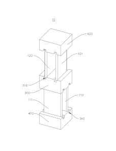
Referring to FIG. 1, the present embodiment provides a piezoelectric actuator
10
comprising a level connector 300, a first piezoelectric single crystal 111, a
second
piezoelectric single crystal 112, a third piezoelectric single crystal 121, a
fourth
piezoelectric single crystal 122, a base 410 and a pedestal 420.
The level connector 300 is used for mounting the first piezoelectric single
crystal 111,
the second piezoelectric single crystal 112, the third piezoelectric single
crystal 121
and the fourth piezoelectric single crystal 122, and can transfer an adjusted
angle.
Preferably, the shape of the main body of the level connector 300 includes,
but is not
limited to, a rectangular or square structure, and in addition, other
irregular shapes
such as a circle and an ellipse are also suitable. The level connector 300 has
two
parallel surfaces, i.e., a first surface and a second surface, opposite to
each other. On
the level connector 300, a recess 310 structure can be provided, with two
recesses on
the first surface and two recesses on the second surface. The recesses 310 are
used to
enhance the stability of the connection between the level connector 300 and
the first
piezoelectric single crystal 111, the second piezoelectric single crystal 112,
the third
piezoelectric single crystal 121 and the fourth piezoelectric single crystal
122 (four
piezoelectric single crystals are respectively embedded into different
recesses 310 and
are fixedly connected thereto). The recesses 310 may be in a strip-shaped
recess 310
structure, but is not limited thereto. The arrangement manner of the recesses
310 (the
connection positions of the piezoelectric single crystals with the level
connector 300)
may be, but is not limited to, that two recesses 310 are arranged in parallel
on the
same surface, and the recess 310 structures on the first surface are arranged
orthogonal (perpendicular) to the recess 310 structures on the second surface.
The first piezoelectric single crystal 111, the second piezoelectric single
crystal 112,
the third piezoelectric single crystal 121 and the fourth piezoelectric single
crystal 122
are used for receiving voltage excitation to deform (mainly change the length)
so as to
drive the devices or components connected to the ends of them.
Preferably, the first piezoelectric single crystal 111 and the second
piezoelectric single
crystal 112 are mounted on the first surface of the level connector 300 and
are
mounted at different positions; and the third piezoelectric single crystal 121
and the
fourth piezoelectric single crystal 122 are mounted on the second surface of
the level
connector 300 and are mounted at different positions, thereby forming a two-
layered
structure. Among the connection positions between the first to fourth
piezoelectric
single crystals 111, 112, 121 and 122 and the level connector 300, the
projections of
the connection positions on the first surface or the second surface of the
level
connector 300 do not overlap each other. When the first piezoelectric single
crystal
7
CA 03035299 2019-02-27
111, the second piezoelectric single crystal 112, the third piezoelectric
single crystal
121, and the fourth piezoelectric single crystal 122 are all of a rectangular
shape (not
limited thereto), it can be understood that they are distributed to intersect
one another,
for example, orthogonal and oblique crossing etc. The connection manner may be
bonding, soldering, welding, etc., which is not limited.
Preferably, when the piezoelectric single crystals are all of a rectangular
shape (i.e.,
single crystal bars), the four piezoelectric single crystals may have the same
size, that
is, each layer is composed of two single crystal bars. When the two single
crystals of
each layer are excited by the same voltage, the front end surfaces thereof
will make
displacement in an axial direction (the axial direction is equivalent to the
direction
perpendicular to the surface of the connecting layer 300), but when they are
excited
by different voltages, the front end surfaces of the two single crystals on
each side can
make axial and tilted displacement (driving surface: a driving surface is
formed by
one end of the third piezoelectric single crystal 121 and one end of the
fourth
piezoelectric single crystal 122 which are not connected with the level
connector 300,
with the driving surface capable of being driven by the third piezoelectric
single
crystal 121 and the fourth piezoelectric single crystal 122 to tilt in a
second direction,
the first direction and the second direction are different directions; and in
this case, the
first piezoelectric single crystal 111 and the second piezoelectric single
crystal 112
drive the level connector 300). One group of single crystals (the third and
fourth
piezoelectric single crystals) are stacked on the other group of single
crystals (the first
and second piezoelectric single crystals), and the tilted rotation axes of the
two groups
of single crystals are in an orthogonal arrangement, so that the
three-degree-of-freedom driving effect can be obtained.
Referring to FIG. 2, this figure shows the post-actuated state of the
piezoelectric
actuator 10. It can be seen that after the first piezoelectric single crystal
111, the
second piezoelectric single crystal 112, the third piezoelectric single
crystal 121 and
the fourth piezoelectric single crystal 122 are excited at different voltages
to undergo
strains, the first piezoelectric single crystal 111 is longer than the second
piezoelectric
single crystal 112, and the third piezoelectric single crystal 121 is longer
than the
fourth piezoelectric single crystal 122, so that the driving surfaces are
finally tilted,
achieving the object of driving.
Preferably, the first piezoelectric single crystal 111, the second
piezoelectric single
crystal 112, the third piezoelectric single crystal 121 and the fourth
piezoelectric
single crystal 122 may be, but are not limited to, [011]-crystal orientation
polarized
lead-based ferroelectric relaxor single crystal, and the components thereof
may be, but
are not limited to, lead zinc niobate-lead titanate (PZN-PT), lead magnesium
niobate-lead titanate (PMN-PT), lead indium niobate-lead magnesium niobate-
lead
titanate (PIN-PMN-PT), lead magnesium niobate-lead zirconate titanate (PMN-
PZT),
and derivative components thereof Such crystal orientation polarized lead-
based
ferroelectric relaxor single crystal has higher transverse piezoelectric
coefficients d31
and d32 than the piezoelectric ceramic. For example, the d32 and d31 values of
the
PZN-PT single crystal are -(3200-4000) pC/N and 1100 pC/N, respectively. This
type
8
CA 03035299 2019-02-27
of piezoelectric material is particularly suitable for the manufacture of
drivers with
high axial strain.
When the excitation field intensity is lower than the intensity of the phase
transformation electric field and the operation frequency is relatively low,
the
transverse-mode bar of the [0111-crystal orientation polarized lead-based
relaxor
single crystal exhibits an extremely low strain hysteresis. Preferably, the
transverse
mode that can be used by the first piezoelectric single crystal 111, the
second
piezoelectric single crystal 112, the third piezoelectric single crystal 121
and the
fourth piezoelectric single crystal 122 in the present invention is [0111-
crystal
orientation polarized, [100]-direction driven d32 mode. For example, such type
of bars
made of PZN-5.5%PT single crystals have a high transverse piezoelectric
coefficient
(d32 -2200-2500 pC/N), high phase transformation electric field and [1001-
direction
high phase transformation stress intensity (the phase transformation electric
field ERO
is 0.8 kV/mm and the phase transformation stress intensity cyRo is 12 MPa). As
shown
in FIG. 3, the field-induced strain curve of the [0111-crystal orientation
polarized
PZN-5.5%PT d32 transverse-mode single crystal bar is shown, in which the
horizontal
axis represents the electric field intensity, and the longitudinal axis
represents the
strain. As can be seen from the figure, this type of single crystals exhibit a
large strain
and no obvious strain hysteresis (wherein the dashed line indicates the ideal
non-hysteresis state, the solid line indicates the actually-measured change,
of which
the minor differences can be ignored and which are very close to the ideal
state). Such
type of single crystals with a large strain and no obvious strain hysteresis
can be used
as a preferred material for manufacturing a driving device for small mirrors
of the
deformable mirror 20.
The base 410 and the pedestal 420 are used for fixing or mounting other
devices, such
as small mirrors.
Preferably, the base 410 is provided at the ends of the first piezoelectric
single crystal
111 and the second piezoelectric single crystal 112 away from the level
connector 300.
The pedestal 420 is provided at the ends of the third piezoelectric single
crystal 121
and the fourth piezoelectric single crystal 122 away from the level connector
300. For
example, the base 410 may be configured as a fixed base, and the pedestal 420
may be
configured as a bearing platform for mounting the driven devices. It should be
noted
that if there are no pedestal and base, it is feasible to directly fix the end
surfaces of
the piezoelectric single crystals at one side onto other planes or devices,
and directly
fixedly connect the end surfaces of the piezoelectric single crystals at the
other side
onto the driven objects or devices, as shown in FIG. 4. Recesses 310 may also
be
provided at the positions, where the pedestal and base are connected with the
first
piezoelectric single crystal 111, the second piezoelectric single crystal 112,
the third
piezoelectric single crystal 121 and the fourth piezoelectric single crystal
122, for
connection.
In the piezoelectric actuator 10 provided in the present invention, the first
surface of
the level connector 300 is provided with the first piezoelectric single
crystal 111 and
9
= CA 03035299 2019-02-27
the second piezoelectric single crystal 112, the second surface of the level
connector
300 is provided with the third piezoelectric single crystal 121 and the fourth
piezoelectric single crystal 122, the first surface and the second surface are
the two
opposite side surfaces of the level connector 300, the first piezoelectric
single crystal
111, the second piezoelectric single crystal 112, the third piezoelectric
single crystal
121 and the fourth piezoelectric single crystal 122 are connected at different
positions
of the level connector 300, and the projections of the connection positions on
the first
surface or the second surface of the level connector 300 do not overlap each
other.
That is, the first piezoelectric single crystal 111 and the second
piezoelectric single
crystal 112 are in a direction, and the third piezoelectric single crystal 121
and the
fourth piezoelectric single crystal 122 are in another direction. In this way,
by
applying a voltage to the first piezoelectric single crystal 111 and the
second
piezoelectric single crystal 112, the first piezoelectric single crystal 111
and the
second piezoelectric single crystal 112 deform (extend or shorten), so as to
adjust the
tilt angle or the lifting height of the level connector 300 in one direction;
and by
applying a voltage to the third piezoelectric single crystal 121 and the
fourth
piezoelectric single crystal 122, the third piezoelectric single crystal 121
and the
fourth piezoelectric single crystal 122 deform, so as to adjust the tilt angle
or the
lifting height of the end surfaces thereof in another direction. The two
adjusted angles
are transferred through the level connector 300 to the ends (the driving
surface formed
by the third piezoelectric single crystal 121 and the fourth piezoelectric
single crystal
122) of the piezoelectric single crystals on the same side of the level
connector 300,
thereby achieving the adjustment of the angles in the two directions.
Moreover, the
adjustment of the axial length can be achieved by the length variations of the
piezoelectric single crystals in the axial direction, that is, three-degree-of-
freedom
control over the piezoelectric actuator 10 is achieved.
Second Embodiment
Referring to FIG. 5, the present embodiment provides a deformable mirror 20
using
the piezoelectric actuator 10 of the first embodiment. FIG. 5 and FIG. 6 are
schematic
structural diagrams of the 9x9 deformable mirror 20 using the piezoelectric
actuator
of the first embodiment in different states.
Preferably, the deformable mirror 20 comprises a plurality of mirror bodies
510 and a
plurality of piezoelectric actuators 10, the mirror bodies 510 each are
located at the
same side of the level connector 300, and the mirror bodies 510 each are
arranged at
the end surfaces of the ends of the first piezoelectric single crystal 111 and
the second
piezoelectric single crystal 112 of one piezoelectric actuator 10, which are
not
connected with the level connector 300; or the mirror bodies 510 each are
arranged at
the end surfaces of the ends of the third piezoelectric single crystal 121 and
of the
fourth piezoelectric single crystal 122 of one piezoelectric actuator 10,
which are not
connected with the level connector 300.
Preferably, the individual mirror bodies 510 respectively may be mounted on
the
bases 410 or the pedestals 420 of the plurality of piezoelectric actuators 10,
and may
'U
CA 03035299 2019-02-27
also be directly connected to the end surfaces of the first piezoelectric
single crystal
111 and the second piezoelectric single crystal 112 away from the level
connector 300,
or directly connected to the end surfaces of the third piezoelectric single
crystal 121
and the fourth piezoelectric single crystal 122 away from the level connector
300. The
unconnected end surfaces may be provided with a base or a pedestal as a fixed
layer
or directly fixed to other devices. Each piezoelectric actuator 10 can
independently
control one mirror body 510. Each mirror body 510 is one of the small mirrors
constituting a complete deformable mirror 20.
Referring to FIG. 6, this figure is a schematic diagram of the deformable
mirror 20
that has been driven by the piezoelectric actuator 10. It can be seen that
after the first
piezoelectric single crystal 111, the second piezoelectric single crystal 112,
the third
piezoelectric single crystal 121 and the fourth piezoelectric single crystal
122 are
excited by different voltages respectively to undergo strains, the first
piezoelectric
single crystal 111 is longer than the second piezoelectric single crystal 112,
and the
third piezoelectric single crystal 121 is longer than the fourth piezoelectric
single
crystal 122, so that the entire surface of the deformable mirror 20 is finally
tilted. Of
course, in practical applications, each piezoelectric actuator 10 is
separately controlled,
and therefore each of the driven mirror bodies 510 may undergo a different
variation.
For the deformable mirror 20 having a certain size, the more small mirror
units it has,
the stronger the optical adaptability thereof is. The number of piezoelectric
small
mirrors in the deformable mirror 20 is generally several tens or even
hundreds, and
these small mirrors need to be separately controlled, thus, strain hysteresis
will
significantly increase the difficulty in the control. The use of such
piezoelectric
actuator 10 will provide the advantages such as high response speed, small
strain
hysteresis and high displacement and improved resolution, which greatly
reduces the
axial and tilted displacement deviations of the piezoelectric actuator, and
also reduces
the difficulty in controlling the piezoelectric actuator in the deformable
mirror 20.
For example, if the above-mentioned small mirrors are driven by four PZN-
5.5%PT
d32 single crystal bars having a size of 7mm (L)x4mm (W)x0.5mm (T), under the
excitation of a 400V unidirectional voltage, the maximum values of the total
axial
displacement and full tilt angle width are 15pm and 0.3 degree, respectively.
For the deformable mirror 20 using the piezoelectric actuator 10 of the first
embodiment provided in the present embodiment, by mounting each of the small
mirror units on the deformable mirror 20 at the ends of the first
piezoelectric single
crystal 111 and the second piezoelectric single crystal 112 of one
piezoelectric
actuator 10 away from the level connector 300, or at the ends of the third
piezoelectric
single crystal 121 and the fourth piezoelectric single crystal 122 of one
piezoelectric
actuator 10 away from the level connector 300, the deformable mirror 20 fixes
the
ends of the piezoelectric single crystals which are connected with the small
mirror
units. By means of the three-degree-of-freedom adjustment of the piezoelectric
actuator 10, it is possible to separately control each of the small mirrors in
three
directions, and by means of control over each small mirrors, the control with
higher
11
CA 03035299 2019-02-27
accuracy over the large curved mirror surface of the entire deformable mirror
20 can
be achieved, which reduces the control difficulty and control hysteresis, and
increases
the control flexibility.
In view of the above, the piezoelectric actuator 10 and the deformable mirror
20
provided in the present invention use the first piezoelectric single crystal
111, the
second piezoelectric single crystal 112, the third piezoelectric single
crystal 121 and
the fourth piezoelectric single crystal 122 to form two groups of two-layered
structures; and the rotation axes of the driving surfaces of each group of
piezoelectric
single crystals intersect so as to achieve, after the excitation by a voltage,
the driving
effect of driving the ends of one group of piezoelectric single crystals away
from the
level connector 300 (tilted displacement and axial displacement in two
directions) to
obtain three degrees of freedom, thereby driving the mirror bodies 510 of the
deformable mirror 20 to achieve multi-degree-of-freedom driving effect.
Third Embodiment
As shown in FIG. 1, the present embodiment provides a piezoelectric actuator
for the
use in a deformable mirror, mainly comprising a level connector 300, a first
piezoelectric single crystal 111, a second piezoelectric single crystal 112, a
third
piezoelectric single crystal 121, a fourth piezoelectric single crystal 122, a
base 410
and a pedestal 420, wherein the first piezoelectric single crystal 111 and the
second
piezoelectric single crystal 112 are provided opposite to each other and
spaced apart,
and have one ends connected with the level connector and the other ends
connected
with the base; and the third piezoelectric single crystal 121 and the fourth
piezoelectric single crystal 122 are provided opposite to each other and
spaced apart,
and have one ends connected with the level connector and the other ends
connected
with the pedestal 420.
As shown in FIG. 1 and FIG. 2, the level connector 300 comprises a first
connection
surface and a second connection surface opposite to each other, one end of the
first
piezoelectric single crystal 111 and one end of the second piezoelectric
single crystal
112 are connected with the first connection surface respectively, the first
piezoelectric
single crystal 111 and the second piezoelectric single crystal 112 are
arranged in
parallel and spaced apart, and the arranging direction of the first
piezoelectric single
crystal and the second piezoelectric single crystal on the first connection
surface is
defined as a first direction. The free ends of the first piezoelectric single
crystal 111
and the second piezoelectric single crystal 112 are provided with a base 410.
Similarly, one end of the third piezoelectric single crystal 121 and one end
of the
fourth piezoelectric single crystal 122 are connected with the second
connection
surface respectively, the third piezoelectric single crystal 121 and the
fourth
piezoelectric single crystal 122 are provided in parallel and spaced apart,
and the
arranging direction of the third piezoelectric single crystal and the fourth
piezoelectric
single crystal on the second connection surface is defined as a second
direction which
is at an angle to the first direction. The free ends of the third
piezoelectric single
12
CA 03035299 2019-02-27
crystal 121 and the fourth piezoelectric single crystal 122 are provided with
a
pedestal.
Further, the first piezoelectric single crystal, the second piezoelectric
single crystal,
the third piezoelectric single crystal and the fourth piezoelectric single
crystal are all
in a rectangular plate-like structure with the same size.
Of course, in other embodiments, it can also be the case that the first
piezoelectric
single crystal 111 and the second piezoelectric single crystal 112 are in a
rectangular
plate-like structure with the same size, and the third piezoelectric single
crystal 121
and the fourth piezoelectric single crystal 122 are in a rectangular plate-
like structure
with the same size; and the two sizes may be different. Alternatively, the
first
piezoelectric single crystal and the second piezoelectric single crystal may
be different
in size, and the third piezoelectric single crystal and the fourth
piezoelectric single
crystal may also be different in size. Alternatively, the four piezoelectric
single
crystals are not necessarily in a rectangular plate shape, instead, they may
have other
suitable shapes, for example, a strip shape.
Further, the level connector 300 is of a plate-like or a block-like structure,
with two
parallel recesses on the first connection surface and also parallel recesses
on the
second connection surface, and the recesses on the first connection surface
and the
recesses on the second connection surface are perpendicular to each other. One
end of
the first piezoelectric single crystal 111 and one end of the second
piezoelectric single
crystal 112 are bonded in the two recesses on the first connection surface
respectively,
and the other end of is bonded in the other recess in the first connection
surface. The
third piezoelectric single crystal 121 and the fourth piezoelectric single
crystal 122 are
respectively bonded in the two recesses on the second connection surface
respectively.
The free ends of the first piezoelectric single crystal 111 and the second
piezoelectric
single crystal 112 are provided with a base 410 having an upper surface
parallel to the
first surface of the level connector 300, and the upper surface is provided
thereon with
two parallel recesses; and the free ends of the first piezoelectric single
crystal 111 and
the second piezoelectric single crystal 112 are respectively bonded in the two
recesses
of the base 410.
The free ends of the third piezoelectric single crystal 121 and the fourth
piezoelectric
single crystal 122 are provided with a pedestal 420. The pedestal 420 has a
lower
surface parallel to the second surface of the level connector 300, with the
lower
surface provided thereon with two parallel recesses; and the free ends of the
third
piezoelectric single crystal 121 and the fourth piezoelectric single crystal
122 are
respectively bonded in the two recesses of the pedestal 420.
Of course, in other embodiments, the first piezoelectric single crystal 111,
the second
piezoelectric single crystal 112, the third piezoelectric single crystal 121
and the
fourth piezoelectric single crystal 122 can be connected with the level
connector 300,
the base 410 and the pedestal 420 in other manners, e.g., bonding. In
addition, it is
13
CA 03035299 2019-02-27
merely a preferred embodiment that the recesses on the first connection
surface are
perpendicular to the recesses on the second connection surface, and in other
embodiments, they may be arranged to form other angles.
The first piezoelectric single crystal 111, the second piezoelectric single
crystal 112,
the third piezoelectric single crystal 121 and the fourth piezoelectric single
crystal 122
use piezoelectric active materials, and when an electric field or a voltage is
applied by
means of an external wire, these single crystals can extend or be contracted,
and the
electrode surfaces of these single crystals are on the two largest surfaces.
For
simplification, the connection wires are not shown in the figure.
Further, the first piezoelectric single crystal 111, the second piezoelectric
single
crystal 112, the third piezoelectric single crystal 121 and the fourth
piezoelectric
single crystal 122 are made of high piezoelectric relaxor solid solution
single crystals,
comprising at least one selected from the group consisting of the following
components: lead zinc niobate-lead titanate (Pb(Zmi3Nb2/3)03-PbTiO3), lead
magnesium niobate-lead titanate (Pb(Mgu3Nb2/3)03-PbTiO3), lead magnesium
niobate-lead zirconate titanate (Pb(Mg1/3Nb2/3)03-PbZr03-PbTiO3), lead indium
niobate-lead magnesium niobate-lead titanate
(Pb(Inu2Nb1/2)03-Pb(MgmNb2/3)03-PbTiO3), and derivative components of them.
That is, the first piezoelectric single crystal 111, the second piezoelectric
single
crystal 112, the third piezoelectric single crystal 121 and the fourth
piezoelectric
single crystal 122 each comprise one or more of the components above.
Under the effects of a low frequency and relatively small external electric
field (with
intensity lower than that of the phase transformation electric field of single
crystal),
the [011]-crystal orientation polarized transverse-mode lead-based relaxor
piezoelectric single crystal exhibits an extremely low strain hysteresis.
Further, the
first piezoelectric single crystal 111, the second piezoelectric single
crystal 112, the
third piezoelectric single crystal 121 and the fourth piezoelectric single
crystal 122 in
the present invention are made of [011]-crystal orientation polarized d32-mode
([100]
crystal orientation is used as the actuating direction) single crystals. For
example, the
[011]-crystal orientation polarized PZN-5.5%PT single crystal not only has a
very
high transverse piezoelectric coefficient d32 -2400 pC/N, but also has a
relatively
high phase transformation electric field and axial phase transformation
stress, which
are 0.8 kV/mm and 10 MPa respectively.
FIG. 3 is an electric field-induced strain curve of the quasi-static [011]-
crystal
orientation polarized d32-mode PZN-5.5%PT crystal, in which the abscissa
indicates
the external electric field intensity (kV/mm), and the ordinate indicates the
induced
strain. The figure shows that the single crystal has good axial strain
linearity and
extremely low strain hysteresis.
In other embodiments, the first piezoelectric single crystal 111, the second
piezoelectric single crystal 112, the third piezoelectric single crystal 121
and the
fourth piezoelectric single crystal 122 can use the [011]-crystal orientation
polarized
d31 mode.
14
CA 03035299 2019-02-27
The working principle of the piezoelectric actuator provided in the present
embodiment is as follows:
After the pedestal 420 is fixed, same voltage is applied to the four
piezoelectric single
crystals, and the four piezoelectric single crystals have the same extending
or
contracting amount, thereby causing the base 410 to move in a direction
perpendicular
to the pedestal 420, i.e., causing axial displacement.
When different voltages are applied to the third piezoelectric single crystal
121 and
the fourth piezoelectric single crystal 122, the deformation amounts of them
are
different, or both the deformation amounts thereof and the deformation
directions
thereof are different, so that the pedestal 420 is tilted, that is,
experiences turnover at a
certain angle, and the rotation axis thereof is parallel with the recesses on
the second
connection surface; and when different voltages are applied to the first
piezoelectric
single crystal 111 and the second piezoelectric single crystal 112, the
deformation
amounts thereof are different, or both the deformation amounts thereof and the
deformation directions thereof are different, so that the level connector 300
is tilted,
the level connector 300 drives, through the third piezoelectric single crystal
121 and
the fourth piezoelectric single crystal 122, the pedestal 420 to tilt and
experience
turnover at a certain angle, and the rotation axis thereof is parallel with
the recesses on
the first connection surface. Since there is an angle between the recesses on
the first
connection surface and the recesses on the second connection surface, in the
two cases,
there is also a certain angle between the rotation axes, and in the present
embodiment,
the angle is 90 , therefore two rotational degrees of freedom are produced,
plus the
free ends making axial displacement, there are three degrees of freedom in
total.
In addition, since the first piezoelectric single crystal 111, the second
piezoelectric
single crystal 112, the third piezoelectric single crystal 121 and the fourth
piezoelectric single crystal 122 are all made of [011]-crystal orientation
polarized
lead-based relaxor single crystals with ultra-high piezoelectric performance,
the
hysteresis effect is so small that it can be ignored.
It should be noted that "parallel" or "perpendicular" mentioned in the present
invention does not mean "absolutely parallel" or "absolutely perpendicular",
rather,
there may be a certain deviation; in addition, the lower surface and the upper
surface
are both mentioned with reference to the drawings, and when the direction in
the
drawings is changed, the positions of the lower surface and the upper surface
will be
changed accordingly.
Fourth Embodiment:
The present embodiment provides a deformable mirror using a plurality of
piezoelectric actuators provided in the third embodiment, the plurality of
piezoelectric
actuators are arranged in a matrix and the bases are fixed on a rigid base.
The upper
surface of the pedestal is subjected to mirror-polishing and is covered with a
coating
having high reflectivity, which is specifically a metal coating. The present
embodiment uses 81 piezoelectric actuators in a 9x9 arrangement.
CA 03035299 2019-02-27
Fifth Embodiment:
The present embodiment provides a method for manufacturing the deformable
mirror,
comprising the steps of:
a. mirror-polishing the upper surface of the pedestal of each of the
piezoelectric
actuators in the third embodiment; and
b. mounting the bases of the piezoelectric actuators on a rigid base and
arranging
the plurality of piezoelectric actuators in a matrix. The bases can be
connected with
the rigid base by welding, bonding, clamping, bolting or the like.
Further, after mirror-polishing is performed, the upper surface of the
pedestal is
covered with a coating having high reflectivity.
Sixth Embodiment
The present embodiment provides a method for manufacturing the deformable
mirror,
comprising the steps of:
a. mounting the bases of the piezoelectric actuators on a rigid base and
arranging
the plurality of piezoelectric actuators in a matrix. The bases can be
connected with
the rigid base by welding, bonding, clamping, soldering, bolting or the like;
and
b. performing flat-lapping of the upper surfaces of the pedestals of the
plurality of
piezoelectric actuators; and
c. bonding a small mirror body onto the upper surface of the pedestal of each
of the
plurality of piezoelectric actuators.
The above are only preferred embodiments of the present invention, which are
not
used to limit the present invention. For a person skilled in the art, the
present
invention may have various modifications and variations. Any modifications,
equivalent substitutions, improvements etc. made within the spirit and
principle of the
present invention shall all be covered by the scope of protection of the
present
invention.
Industrial Applicability
According to the piezoelectric actuator provided in the present invention, a
first
surface of a level connector is provided with a first piezoelectric single
crystal and a
second piezoelectric single crystal, a second surface of the level connector
is provided
with a third piezoelectric single crystal and a fourth piezoelectric single
crystal, the
first surface and the second surface are two opposite side surfaces of the
level
connector, the first piezoelectric single crystal, the second piezoelectric
single crystal,
the third piezoelectric single crystal and the fourth piezoelectric single
crystal are
connected at different positions of the level connector, and the projections
of the
connection positions on the first surface or the second surface of the level
connector
do not overlap each other. That is, the first piezoelectric single crystal and
the second
piezoelectric single crystal are in one direction, and the third piezoelectric
single
16
CA 03035299 2019-02-27
crystal and the fourth piezoelectric single crystal are in another direction.
In this way,
by applying a voltage to the first piezoelectric single crystal and the second
piezoelectric single crystal, the first piezoelectric single crystal and the
second
piezoelectric single crystal deform (extend or shorten), so as to adjust the
tilt angle or
the lifting height of the level connector in one direction; and by applying a
voltage to
the third piezoelectric single crystal and the fourth piezoelectric single
crystal, the
third piezoelectric single crystal and the fourth piezoelectric single crystal
deform, so
as to adjust the tilt angle or the lifting height of the end surfaces thereof
in another
direction. The two adjusted angles are transferred through the level connector
to the
ends (the driving surfaces formed by the third piezoelectric single crystal
and the
fourth piezoelectric single crystal) of the piezoelectric single crystals on
the same side
of the level connector, thereby achieving the adjustment of the angles in the
two
directions. Moreover, the adjustment of the axial length can be achieved by
the length
variations of the piezoelectric single crystals in the axial direction, that
is, the
three-degree-of-freedom control over the piezoelectric actuator is achieved.
For the deformable mirror using the piezoelectric actuator according to the
present
invention, by mounting each of the small mirror units on the deformable mirror
at the
ends of the first piezoelectric single crystal and of the second piezoelectric
single
crystal of one piezoelectric actuator away from the level connector, or at the
ends of
the third piezoelectric single crystal and of the fourth piezoelectric single
crystal of
one piezoelectric actuator away from the level connector, the deformable
mirror fixes
the ends of the piezoelectric single crystals which are connected with the
small mirror
units. By means of the three-degree-of-freedom adjustment of the piezoelectric
actuator, it is possible to separately control each of the small mirrors in
three
directions, and by means of the control over each small mirrors, it is
possible to
achieve control with high accuracy over the large curved mirror surface of the
entire
deformable mirror, which reduces the control difficulty and control
hysteresis, and
increases the control flexibility.
17