Note: Descriptions are shown in the official language in which they were submitted.
CA 03035714 2019-03-04
SPECIFICATION
INDUSTRIAL TWO-LAYERED FABRIC
TECHNICAL FIELD OF THE INVENTION
[ 0 0 0 1 ]
The present invention relates to an industrial two-layered fabric with a long
durability
which exhibits an excellent surface smoothness and an excellent marking
characteristics,
while at the same time balancing warps and wefts.
BACKGOUND ART
[ 0 0 0 2]
Fabrics obtained by weaving warps and wefts have conventionally been used
widely as
an industrial two-layered fabric. They are, for example, used in various
fields including
papermaking fabrics, conveyor belts and filter cloths and are required to have
fabric
properties suited for the intended use or using environments. Of such fabrics,
a
papermaking fabric used in a papermaking step for removing water from raw
materials by
making use of the network of the fabric must satisfy a severe demand.
For example, there is a demand for the development of fabrics which do not
transfer a
wire mark of the fabric and therefore have excellent surface property, the
ones which have
enough hydration property for sufficiently and uniformly hydrating excess
water contained
in the material and enough rigidity or wear resistance to be usable desirably
even under
severe environments, or the ones which are capable of maintaining conditions
necessary for
making good paper for a prolonged period of time.
In addition, a fiber supporting property, improvement in a paper making yield,
dimensional stability and running stability are demanded.
In recent years, owing to the speed-up of a paper making machine, requirements
for
papermaking fabrics have become even severe.
[ 0 0 0 3 ]
Since most of the demands for industrial fabrics and solutions thereof can be
understood
if papermaking fabrics on which the most severe demand is imposed among
industrial
fabrics is described, the papermaking fabric will hereinafter be described as
a
representative example.
Recently, particularly excellent hydration property and surface smoothness
have been
required due to the high speed operation of a machine for fabric. Although the
required
hydration property varies in accordance with the machine and the product
papers, the
uniform hydration property and the fiber supportability are commonly required
for all the
product papers. In addition, the fiber supportability is considered to be
crucial, since old
papers in which much fine fibers are contained has been increasingly used in
recent years,
and the fabric with an excellent hydration property has become required, since
the
1
CA 03035714 2019-03-04
hydration property is decreased upon the formation of the sheet with much fine
fibers
contained therein.
Further, in the fabric for producing papers, a hydration operation in a
centrifugal or a
pressing manner is generally conducted by utilizing a network of the fabric,
however, water
is sucked to be hydrated from an underside of the network in order to obtain a
sufficient
hydration property, so that the required properties such as the fiber
supportability, the
hydration property influences much on the operation or the cost for producing
papers.
[ 0 0 0 4 ]
In this connection, it is publicly known that the diameters of the upper
surface side
warps and the upper surface side wefts may be preferably reduced, while at the
same time,
the number of the yarns may be preferably increased in order to improve the
surface
smoothness of such an industrial two-layered fabric.
On the other hand, it is publicly known that the diameters of the lower
surface side wefts
arranged to be the running side which contacts the machine may be preferably
increased in
order to improve the wear resistance. However, it is widely known that the
balance of the
lower surface side fabric layer can be worsened by the fact that the diameter
of the lower
surface side weft larger than that of the lower surface side warp due to the
thickening of
the lower surface side weft.
Here, the industrial fabric in which the diameter of each of two kinds of
yarns, that is,
the lower surface side warps and the lower surface wefts constituting the
lower surface side
fabric is set to be larger than the diameter of each of the upper surface side
warps and the
upper surface wefts opposed to the lower surface side warps and the lower
surface wefts
has been developed (refer to Patent Publication 1) . A technical problem of
the wear
resistance is considered to be solved by using such an industrial fabric.
[ 0 0 0 5 ]
However, the industrial fabric disclosed in the Patent Publication 1 is the
one in which
the upper surface side fabric layer and the lower surface side fabric layer
are bound by the
wefts. Accordingly, a technical problem which arises in a case where the
industrial
two-layered fabric is bound by the warps is not taken into account. If the
diameters of yarns
only constituting the lower surface side fabric are made large and the
industrial fabric is
bound by the warps in the industrial fabric disclosed in the Patent
Publication 1, the warps
with small diameters and the warps with large diameters being woven with the
upper
surface side wefts from the lower surface side are mixed on the surface of the
fabric.
Therefore, since undulation due to the warps is caused to generated on the
upper surface
side fabric, the surface smoothness is deteriorated.
In addition, there is a risk in which the warps serving as binding yarns which
are woven
with the lower surface side wefts with large diameters can be cut with time.
The tensions of
the warps are high, as compared with the wefts, so that another technical
problem in which
the durability of the fabric can be worsened, since the cutting problem of the
warps leads to
the destruction of the fabric.
2
CA 03035714 2019-03-04
Such being the case, the present invention was made in order to solve the
technical
problem of the conventional technology such as the worsening of the surface
smoothness,
the deterioration of the durability of the fabric under the fabric with the
diameter of the
yarns on the lower surface side fabric being set to be larger than the
diameter of the yarns
on the upper surface side fabric.
[ 0 0 0 6]
Patent Publication 1: International Publication W02014/202277
DISCLOSURE OF THE INVENTION
TECHNICAL PROBLEMS TO BE SOLVED BY PRESENT INVENTION
[ 0 0 7 ]
The object of the present invention is to provide an industrial two-layered
fabric with a
long durability which exhibits an excellent surface smoothness and excellent
marking
characteristics, while at the same time improving wear resistance
characteristics to
balance warps and wefts.
MEANS TO SOLVE TECHNICAL PROBLEMS
[0 0 0 8 ]
The industrial fabric of the present invention includes following technical
features in
order to solve the above technical problems.
(1) An industrial two-layered fabric formed by binding at least one upper
surface side fabric
constituted by upper surface side warps and upper surface side wefts and at
least one lower
surface side fabric constituted by lower surface side warps and lower surface
side wefts, by
binding yarns, diameters of all of the upper surface side warps are set to be
the same,
diameters of all of the lower surface side warps are set to be the same,
diameters of the
lower surface side warps are set to be larger than diameters of said upper
surface side
warps, and at least one, or more than one of said upper surface side warps are
woven with
said lower surface side wefts to constitute binding yarns binding said at
least one upper
surface side fabric and said at least one lower surface side fabric.
[0 0 0 9 ]
Here, by setting the diameters of the lower surface side warps to be larger
than the
diameters of the upper surface side warps, the balance between the warps and
the wefts
can be improved, as compared with the lower surface side warps with small
diameters. In
particular, in a case where the diameters of the lower surface side warps are
set to be
larger than the diameters of the upper surface side warps in order to improve
the wear
resistance, the balance of the two-layered fabric can be improved. In
addition, the cutting
of the warps due to the wear can be reduced by setting the diameter of the
lower surface
3
CA 03035714 2019-03-04
side warps to be large, so that the two-layered fabric with an excellent
durability can be
provided.
Further, the worsening of the surface property can be prevented by adopting
the binding
yarns of only the upper surface side warps, not by adopting the binding yarns
of the
lower surface side warps. In particular, in the present invention, the upper
surface side
fabric with different diameters are not mixed by adopting all the lower
surface side
warps as the binding yarns, setting the diameters of all the upper surface
side warps to
be the same, and setting the diameters of all the lower surface side warps to
be the same,
so that the worsening of the surface property can be prevented, whereby the
surface
smoothness and the marking characteristics can be improved.
[0 0 1 0
(2) The industrial two-layer layered fabric according to claim 1, wherein the
difference of
the diameters between said upper surface side warps and said lower surface
side warps are
set be within a range of the following equation.
the diameter of lower surface side warp(q) / the diameter of upper surface
side
warp ((p)=1<q) < =2
Here, in a case where the diameter of lower surface side warp(q) / the
diameter of upper
surface side warp ((p) is smaller than, or equal to 1, the wear resistance
cannot be
improved, as compared the conventional fabric. In a case where the diameter of
lower
surface side warp(q) / the diameter of upper surface side warp (cp) is larger
than 2, since
the density of the warps on the upper surface side warps becomes too small,
the surface
property on the upper surface side fabric can be worsened.
In view of the above, it is more preferable that the diameter of lower surface
side warp(p)
/ the diameter of upper surface side warp (p) be between 1.2 and 1.5.
[ 0 0 1 1]
(3) The industrial two-layer layered fabric according to claim 1 or 2, wherein
the difference
of the diameters between said lower surface side warps and said lower surface
side wefts
are set be within a range of the following equation.
the diameter of lower surface side weft(p) / the diameter of lower surface
side warp
((p)-=1<q) < = 2
Here, in a case where the diameter of lower surface side weft(p) / the
diameter of upper
surface side warp ((p) is smaller than or equal to 1, the quality can be
deteriorated, in view
of the wear resistance. In addition, in a case where the diameter of lower
surface side
weft(w) / the diameter of upper surface side warp (cp) is larger than 2.5,
since the diameter
of the lower surface side weft becomes larger than that of the upper surface
side warp, the
balance of the lower surface side fabric can be worsened, and as a result, the
total property
of the industrial two-layered fabric can be deteriorated.
4
CA 03035714 2019-03-04
. .
In view of the above, it is more preferable that the diameter of lower surface
side
warp(()) / the diameter of upper surface side warp, binding yarn of the upper
surface side
warp and binding yarn of the lower surface side warp (cp) be between 1.2 and
2.3.
[ 0 0 1 2]
EFFECT OF THE INVENTION
According to the industrial two-layered fabric of the present invention, by
adopting an
industrial two-layered fabric with a long durability, an excellent surface
smoothness and an
excellent marking characteristics can be improved, while at the same time wear
resistance
characteristics can be improved.
[ 0 0 1 3 ]
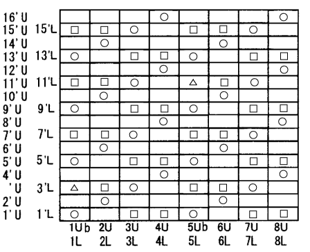
BRIEF EXPLANATION OF DRAWINGS
Fig.1 is a design view of the industrial two-layered fabric according to the
first
embodiment of the present invention.
Fig.2 is a longitudinal cross section view showing a structure of the yarns
with respect to
the industrial fabric according to the first embodiment of the present
invention.
[ 0 0 1 4]
DETAILED DESCRIPTION OF THE INVENTION
Now, the structure and the effect of the fabric of the present invention will
be described
below. Since the following embodiment is a mere example of the present
invention, any
embodiment which is not explicitly described below can be within the scope of
the present
invention.
The industrial two-layered fabric of this embodiment is constituted by binding
the upper
surface side fabric including the upper surface side warps and the upper
surface side wefts
and the lower surface side fabric including the lower surface side warps and
the lower
surface side wefts by means of the binding yarns.
[ 0 0 1 5]
No particular limitation is imposed on a yarn to be used in the present
invention and it
can be selected freely depending on the properties which an industrial fabric
is desired to
have. Examples of it include, in addition to monofilaments, multifilaments,
spun yarns,
finished yarns subjected to crimping or bulking such as so-called textured
yarn, bulky yarn
and stretch yarn, and yarns obtained by intertwining them. As the cross-
section of the yarn,
not only circular form but also square or short form such as stellar form, or
elliptical or
hollow form can be used. The material of the yarn can be selected freely and
usable
examples of it include polyester, polyamide, polyphenylene sulfide,
polyvinylidene fluoride,
polypropylene, aramid, polyether ketone, polyethylene naphthalate,
polytetrafluoroethylene, cotton, wool and metal. Of course, yarns obtained
using
copolymers or incorporating or mixing the above-described material with a
substance
selected depending on the intended purpose may be used.
5
CA 03035714 2019-03-04
[ 0 0 1 61
Here, in the fabric of the present invention, the diameters of all the upper
surface side
warps are set to be the same. In addition, the diameters of all the lower
surface side warps
are set to be same.
Further, the diameters of the lower surface side warps are set to be larger
than the
diameters of the upper surface side warps, so that the industrial fabric is
formed by at least
one, or more than one of the upper surface side warps being woven with the
lower surface
side wefts.
In a case where the diameters of the lower surface side wefts are set to be
larger than the
diameters of the upper surface side wefts, the balance of the two-layered
fabric can be
improved. In addition, the cutting of the warps due to their wear can be
alleviated by
setting the diameters of the lower surface side warps to be large, so that the
two-layered
fabric with a long durability can be provided.
Further, the worsening of the surface property can be prevented by adopting
the binding
yarns of only the upper surface side warps, not by adopting the binding yarns
of the lower
surface side warps. In particular, in the present invention, the upper surface
side fabric
with different diameters are not mixed by adopting all the lower surface side
warps as the
binding yarns, setting the diameters of all the upper surface side warps to be
the same, and
setting the diameters of all the lower surface side warps to be the same, so
that the
worsening of the surface property can be prevented, whereby the surface
smoothness and
the marking characteristics can be improved.
[ 0 0 1 7]
Now, the embodiments of the present invention will be described below with
reference to
the drawings. Fig.1 is a design view of the industrial two-layered fabric
according to the
first embodiment of the present invention.Fig.2 is a longitudinal cross
section view showing
a structure of the yarns with respect to the industrial fabric according to
the first
embodiment of the present invention.
Here, the design view corresponds to the complete structure of the fabric
defining the
minimum unit to be repeated of the fabric structure. A structure of the whole
fabric is
formed by the complete structures woven with each other in the upper and lower
directions,
and in the left and right directions. In addition, the longitudinal cross
sectional view is the
one showing a situation in which the warps are woven with each other in the
complete
structure ....................................................................
In each of the design views, the warp is indicated by a reference number such
as
1,2,3 .......................................................................
The warp binding yarn weaving the upper and lower wefts is indicated by the
reference number to which b is attached. The upper and lower warps are
indicated by the
reference number to which U and L are attached, respectively. In each of the
design views,
the warps with the same reference numbers indicate to form a set, so that, in
Fig.1, the
upper surface side warp U and the lower surface side warp L, the upper surface
side
binding yarn Ub and the lower surface side warp L form a set, respectively,
for instance.
The weft is indicated by a reference number such as 1',2' ,3' ......... .
There is a case in which
6
CA 03035714 2019-03-04
the upper surface side wefts and the lower surface side wefts are arranged
upper and lower,
respectively, and there is another case in which the only upper surface side
wefts are
arranged upper, in accordance with an arrangement ratio of the wefts. The
upper surface
side wefts is indicated by the reference number to which U is attached,
whereas, the lower
surface side wefts is indicated by the reference number to which L is
attached, 1'U, 1' L,
etc., for instance.
[ 0 0 1 81
In each of the design views, a symbol "a" indicates that the lower surface
side warp (L) is
arranged below the lower surface side weft to form a knuckle, and a symbol "0"
indicates
that the upper surface side warp (U) is arranged above the upper surface side
weft to form
a knuckle, and a symbol "A" indicates that the binding yarn of the upper
surface side warp
(Ub) is arranged below the lower surface side weft to form a knuckle. More
specifically, all
the symbols show a position where the upper surface side fabric and the lower
surface side
fabric area bound with each other.
In the design view, the warps and the wefts on the upper surface side are
depicted to be
precisely arranged over the warps and the wefts on the upper surface side,
because of the
clarity of the drawing. In the real fabric, it does not matter if they are
arranged to be offset.
[ 0 0 1 9]
First Embodiment
Figs.1 to 2 are a design view and a cross section view showing an industrial
two-layered
fabric according to the first embodiment, respectively.
As shown in Figs.1 and 2, the industrial two-layered fabric of the first
embodiment
includes upper surface side warps (1U-8U), lower surface side warps (1L-8L),
and upper
surface side warps lUb, 5Ub each serving as a binding yarn. In this
connection, the
diameters of all the upper surface side warps (1U-8U) including the upper
surface side
warps 1U and 5Ub serving as the binding yarns are set to be same. In addition,
the
diameters of all the lower surface side warps (1L-80are set to be same.
[ 0 0 2 0]
As shown in Fig.2, the technical feature of this embodiment is that the
diameters of the
lower surface side warps (1L-8L) are set to be larger than the diameters of
the upper
surface side warps (1U-8U). By adopting such a structure, the cutting of the
warps due to
their wear can be alleviated, so that the industrial two-layered fabric with
an excellent
durability can be provided.
Further, as shown in Figs.1 and 2, the industrial fabric of the first
embodiment includes
upper surface side wefts (1'U-16'U), and lower surface side wefts (1'L, 3'L,
5'L,7'L,9'L, 11'L,
7
CA 03035714 2019-03-04
131,15V to form sixteen shafts.
An arranging ratio of the upper surface side wefts (l'U-16'U) to the lower
surface side
wefts (FL, 3'L = = = =) is two.
[0 0 2 1]
In the first embodiment, as shown in Fig.2, the upper surface side warps 1U-8U
pass
below the three upper surface side wefts and above the one upper surface side
weft. In
addition, the lower surface side warps 2L, 3L, 4L,6L,7L, 8L pass below the one
lower
surface side weft and above the one lower surface side weft in an alternate
manner. Further,
the lower surface side warp 1Lb which serves as the binding yarn passes above
the upper
surface side weft 1'U toward the lower surface side to pass below the lower
surface side
weft 5'L, the lower surface side weft 9'L and the lower surface side weft
13'L.
In addition, the upper surface side warp lUb serving as the binding yarn
passes above
the upper surface side weft 1'U toward the lower surface side to pass below
the lower
surface side wefts 3'L, and then, toward the upper surface side again to
passes above the
upper surface side weft 5'U to bind the upper surface side fabric and the
lower surface side
fabric, and then, passes below the upper surface side wefts 6'U ¨ 8'U to pass
above the
upper surface side weft 9'U and below the upper surface side wefts 10'U ¨ 12'U
and then,
passes above the upper surface side weft 13'U and below the upper surface side
wefts 14'U
¨ 16'U.
[ 0 2 2 ]
In addition, as shown in Fig.2, the upper surface side warp 5Ub serving as the
binding
yarn passes above the upper surface side weft 1'U to pass below the upper
surface side
wefts 2'U ¨ 4'U, and then, passes above the upper surface side weft 5'U to
pass below the
upper surface side wefts 6'U ¨ 8'U, and then, passes above the upper surface
side weft 9'U
toward the lower surface side to pass below the lower surface side wefts 11'L,
and then,
toward the upper surface side again to pass above the upper surface side weft
13'U to bind
the upper surface side fabric and the lower surface side fabric, and then,
passes below the
upper surface side wefts 4'U ¨ 16'U.
In the industrial two-layered fabric of the first embodiment, by adopting such
a structure,
as shown in Fig 2, the upper surface side fabric with the warps of different
diameters are
not adapted to be mixed with each other. As a result, the worsening of the
surface property
can be prevented, so that the surface smoothness and the marking
characteristics can be
improved.
[0 0 2 3]
lUb, 5Ub upper surface side warp serving as binding yarn
2U-4U, 6U-8U upper surface side warp
1 L ¨ 8 L lower surface side warp
8
CA 03035714 2019-03-04
,
1'U--16'U upper surface side weft
l'L, 3'L, 5'L, 7'L ,9'L, 11'L, 13'L, 15'L lower surface side weft
9