Note: Descriptions are shown in the official language in which they were submitted.
=
ELECTRICAL FLOOR BOX WITH LIGHT SOURCE ASSEMBLY
Field of the Invention
[0001] The present invention relates to electrical floor boxes, and more
particularly, to an electrical floor box with a light source assembly
configured to
automatically illuminate the interior thereof when the electrical floor box is
open.
Background
[0002] Generally, electrical floor boxes are installed and used in
buildings to
provide electrical power and/or data in areas where wall outlet boxes are not
available.
These electrical floor boxes are normally installed into a floor so that
wires/cables can
installed underneath the floor. A typical electrical floor box includes a body
and a cover
attached to the body to open and close the interior of the electrical floor
box. While
various electrical devices/components are contained within the interior of the
body of the
box, it can be difficult to locate certain components in the dark and without
an adequate
lighting system.
[0003] Accordingly, although various electrical floor boxes are
currently
available in the marketplace, there is a need for an electrical floor box with
a light source
assembly such that the interior of the electrical floor box can be illuminated
when it is
open.
1
CA 3035776 2019-03-06
Summary
[0004] According to an embodiment of the present invention, an
electrical floor box
includes a body having an open top and defining an interior therewithin, a
cover flange configured to
be mounted on the open top of the body, a cover assembly connected to the
cover flange such that it
is repositionable between open and closed positions, and a light source
assembly arranged within the
electrical floor box. The light source assembly includes a magnet attached to
a bottom surface of the
cover assembly, a magnet reed switch installed on the cover flange, a LED
light electrically
connected to the magnetic reed switch, and a wiring tunnel configured to hold
the LED light
therewithin. When the cover assembly is in the open position, the magnet
disengages with the
magnet reed switch such that the LED light illuminates the interior of the
electrical floor box.
According to an aspect of the present invention, there is provided an
electrical floor
box comprising:
a body having an open top and defining an interior therewithin;
a cover flange configured to be mounted on the open top of the body, the cover
flange
including a plurality of inner tab members that extend laterally from each
side of the cover flange
toward a center of the cover flange, wherein one of the inner tab members
includes a switch wire
aperture passing therethrough;
a cover assembly connected to the cover flange such that the cover assembly is
repositionable between open and closed positions; and
a light source assembly arranged within the electrical floor box, the light
source assembly
including:
a magnet attached to a bottom surface of the cover assembly;
a magnet reed switch having magnetic reed switch wires, the magnet reed switch
installed on the cover flange;
a LED light electrically connected to the magnetic reed switch, wherein in the
closed
position of the cover assembly the magnet engages the magnet reed switch to
turn the LED
light off and in the open position the magnet is disengaged from the magnet
reed switch to
turn the LED light on; and
2
Date Recue/Date Received 2021-01-29
a wiring tunnel having an open end and the LED light is inserted through the
open
end of the wiring tunnel, wherein the wiring tunnel is installed on a bottom
of the cover
flange and the wiring tunnel includes top and bottom members defining a wiring
aperture
that is aligned with the switch wire aperture of the cover flange, the
magnetic reed switch
wires passing through the aligned apertures into the interior of the body of
the electrical floor
box.
[0005] These and other aspects of the present invention will be better
understood in view of
the drawings and following detailed description.
Brief Description of the Drawin2s
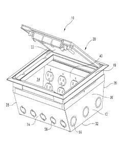
[0006] Figure 1 is a perspective view of an electrical floor box,
according to an embodiment
of the present invention, in an open position;
[0007] Figure 2 is a perspective view of the electrical floor box in
Figure 1 in a closed
position;
[0008] Figure 3 is side view of the electrical floor box in Figure 1;
2a
Date Recue/Date Received 2021-01-29
100091 Figure 4 is an exploded perspective view of the electrical floor
box in
Figure 1; and
100101 Figure 5 is a cross-sectional view of Figure 3.
Detailed Description
100111 According to an embodiment of the present invention, referring to
Figure
1, there is shown an electrical floor box 10 adapted to be installed into a
floor receiving
hole of a floor structure. The electrical floor box 10 is designed and
configured to
provide a housing, such that one or more electrical components (e.g.,
electrical power
receptacles, data connections, etc.) can be disposed/installed therewithin.
100121 Referring to Figures 1-5, the electrical floor box 10 includes a
body 12
defining an interior 14, a light source assembly 16 configured to illuminate
the interior 14
of the body 12, a cover flange 18 configured to be disposed on a top of the
body 12, and a
cover assembly 20 connected to the cover flange 18 that is repositionable
between open
(Figure 1) and closed (Figure 2) positions so as to cover and uncover the
interior 14 of
the body 12.
[00131 Directional terms, such as front, rear, top, and bottom are
referenced to an
orientation in which the electrical floor box 10 is placed such that, when it
is in the open
position, a bottom surface 22 of the cover assembly 20 faces forward. However,
the
present invention is not thereby limited to use in any particular orientation.
3
CA 3035776 2019-03-06
[0014] Referring again to Figures 1-3, in the depicted embodiment, the
body 12 is
a generally rectangular housing having an open top. The body 12 includes
opposed
inclined front and rear walls 24, 26, opposed first and second side walls 28,
30, and a
base 32 extending between the walls 24, 26, 28, 30. Thus, the front and rear
walls 24, 26
are separated by the base 32, and the first and second side walls 28, 30 are
also separated
by the base 32.
[0015] The side walls 28, 30 are connected to the base 32 and extend
laterally
upward therefrom such that they are substantially perpendicular to the base
32. The
inclined front and rear walls 24, 26 are also connected to the base 32 and
extend laterally
upward therefrom with an obtuse angle relative to the base 32. The front wall
24, rear
wall 26, side walls 28, 30, and the base 32 of the body 12 cooperatively
define the
interior 14 for housing electrical components.
[00161 Referring to Figures 4 and 5, each of the front and rear walls
24, 26
includes a flat top 34 and a flange 36. As shown in Figure 5, each flange 36
extends
laterally from the flat top 34 and towards the center of the body 12 with a
recess 38
therebetween. The recess 38 allows a power plate 40 and a data plate 42 to be
secured
onto the flanges 36, as will be described in greater detail below.
[0017] A plurality of cover mounting holes 44 extend through each flat
top 34 of
the body 12 such that the cover flange 18 can be attached to the body 12. A
plurality of
4
CA 3035776 2019-03-06
plate mounting holes 46 are defined on each flange 36 of the body 12 to secure
the power
plate 40 and data plate 42 thereon and within the interior 14 of the body 12,
as shown in
Figure 4. Specifically, a top member 48, 50 of each of the power plate 40 and
data plate
42 is engaged with and secured to the corresponding flange with fasteners (not
shown)
such as screws. Each plate 40, 42 includes an inclined member 52 with a
plurality of
apertures 54 defined thereon. The plurality of apertures 54 allow electrical
and
communication (data) outlets to be placed and fastened therewithin.
[0018] A plurality of knockouts 56 are defined and stamped onto the
walls 24,
26, 28, 30 and the base 32 of the body 12 to provide a convenient method of
creating
knockout openings thereon to allow routing of electrical and communication
wires (not
shown) to and from the body 12. The plurality of knockouts 56 may be
constructed as
multiple ring knockouts to provide various sizes for the knockout openings on
the body
12. The plurality of knockouts 56 may be removed prior to mounting the body 12
to a
floor.
[0019] Referring more particularly to Figure 4, the cover flange 18
defines a
cover flange opening 58 and is dimensioned and configured to be mounted on the
open
top of the body 12. The cover flange 18 includes a plurality of inner tab
members 60 that
extend laterally from each side and towards the center of the cover flange 18.
In the
depicted embodiment, a switch wire aperture 62 is defined on the right inner
tab member
of the cover flange 18, through which magnetic reed switch wires 64 can be
passed
through and placed into the interior 14 of the body 12. Alternatively, the
switch wire
CA 3035776 2019-03-06
aperture 62 may be defined on any one of the inner tab members 60 of the cover
flange
18.
[0020] The cover flange 18 may be attached to the body 12 from the open
top
thereof with fasteners, such as screws. Specifically, the cover flange 18 is
placed over
the open top of the body 12 such that a plurality of cover flange mounting
holes 66
defined on the inner tab members 60 align with the plurality of cover mounting
holes 44
on the flat tops 34 of the body 12. Thereafter, fasteners can be inserted
through the
aligned holes 66, 44 to affix the cover flange 18 onto the body 12.
[0021] The cover assembly 20 is configured to cover and protect the
electrical
components disposed within the interior 14 of the body 12. In addition, the
cover
assembly 20 provides an access to various components disposed within the body
12 when
the cover assembly 20 is in the open position.
100221 The cover assembly 20 includes a cover lid 68, a metal plate 70,
and a
wiring access member 72. The cover lid 68 is hingedly connected and secured to
the
cover flange 18 and moveable between the open and closed positions. A cover
lid recess
74 is defined throughout a top of the cover lid 68 such that the metal plate
70 can be
seated therewithin and secured to the cover lid 68 using fasteners such as
screws. The
wiring access member 72 is hingedly connected to the cover lid 68 at a front
portion
thereof. A lined cushioned material 76, such as foam rubber, is attached to a
bottom
6
Date Recue/Date Received 2020-08-12
surface of the wiring access member 72. The cushioned material 76 prevents
abrading
and damages to wires that pass through the wiring access member 72.
[0023] Referring again to Figures 4 and 5, in the depicted embodiment,
the light
source assembly 16 is installed and arranged within the interior 14 of body 12
of the
electrical floor box 10. The light source assembly 16 includes a magnet 78, a
magnet
reed switch 80 installed on the cover flange 18, a LED light 82 electrically
connected to
the magnetic reed switch 80, and a wiring tunnel 84 configured to hold the LED
light 82.
The magnet 78 is attached to the bottom surface of the cover lid 68 such that
it aligns and
magnetically adheres with the magnet reed switch 80 when the cover assembly 20
is in
the closed position. Thus, when the cover assembly 20 is open, the magnet 78
disengages
with the magnet reed switch 80, allowing the magnet reed switch 80 to turn on
the LED
light 82. Likewise, when the cover assembly 20 is closed, the magnet 78
engages with
the magnet reed switch 80, allowing the magnetic reed switch 80 to turn off
the LED
light 82.
[0024] In the depicted embodiment, the wiring tunnel 84 is secured to
the bottom
of the right inner tab member of the cover flange 18, as shown in Figure 5, to
provide a
means for holding the LED light 82. Specifically, the LED light 82 can be
placed and
disposed within the wiring tunnel 84 by inserting into an open end 86 of the
wiring tunnel
84. A wiring aperture 88 is defined on top and bottom members 90, 92 of the
wiring
tunnel 84 such that, when the wiring tunnel 84 is secured to the cover flange
18, the
switch wire aperture 62 of the cover flange 18 and the wiring aperture 88 of
the wiring
7
CA 3035776 2019-03-06
tunnel 84 align. The aligned apertures 62, 88 provide a pathway for the
magnetic reed
switch wires 64 to enter the interior 14 of the body 12.
100251 In the depicted embodiment, electrical power for the light source
assembly
16 is supplied by AC power, such as 120 VAC. Alternatively, the magnet reed
switch 80
may be electrically connected to a battery source for supplying electrical
power for the
light source assembly 16.
[0026] Referring again to Figure 4, the electrical floor box 10 may
further include
a gasket 94 having a gasket opening 96. The gasket 94 is disposed and arranged
between
the cover flange 18 and the cover assembly 20 to provide environmental
protection when
the cover assembly 20 is in the closed position. Specifically, the gasket 94
may be
retained on the undersurface of the cover lid 68 and engage with the inner tab
members
60 of the cover flange 18. In the depicted embodiment, a magnet reed switch
aperture 98
is defined on a right inturned member 100 of the gasket 94, through which the
magnet
reed switch 80 can be placed therewithin. Alternatively, the magnet reed
switch aperture
98 may be defined on any one of the intumed members of the gasket 94. Once the
gasket
94 is secured to the cover flange 18, the gasket opening 96 aligns with the
cover flange
opening 58.
[0027] From the foregoing, it will be appreciated that an electrical
floor box
according to the present application includes a light source assembly such
that when the
8
CA 3035776 2019-03-06
floor box is open, the light source assembly illuminates the interior of the
electrical floor
box.
[0028] According to one aspect of the present application, an electrical
floor box
includes a body having an open top and defining an interior therewithin, a
cover flange
configured to be mounted on the open top of the body, a cover assembly
connected to the
cover flange such that it is repositionable between open and closed positions,
and a light
source assembly arranged within the electrical floor box. The light source
assembly
includes a magnet attached to a bottom surface of the cover assembly, a magnet
reed
switch having magnetic reed switch wires with the magnet reed switch installed
on the
cover flange, a LED light electrically connected to the magnetic reed switch,
and a wiring
tunnel having an open end, the wiring tunnel configured to hold the LED light
therewithin.
[0029] In one embodiment, the magnet reed switch is positioned on the
cover
flange such that, when the cover assembly is in the closed position, the
magnet
magnetically adheres to the magnet reed switch. In another embodiment, when
the cover
assembly is in the open position, the magnet disengages with the magnet reed
switch such
that the LED light illuminates the interior of the electrical floor box.
[0030] In yet another embodiment, the cover flange includes a plurality
of inner
tab members that extend laterally from each side of the cover flange and
towards the
center of the cover flange. In a refinement of this embodiment, a switch wire
aperture is
defined on one of the inner tab members of the cover flange, through which the
magnetic
9
CA 3035776 2019-03-06
reed switch wires can be passed through and placed into the interior of the
body of the
electrical floor box.
100311 In a further embodiment, the wiring tunnel is secured to the
bottom of the
cover flange. In a refinement of this embodiment, a wiring aperture is defined
on top and
bottom members of the wiring tunnel such that, when the wiring tunnel is
secured to the
bottom of the cover flange, the switch wire aperture and the wiring aperture
align to
provide a pathway for the magnetic reed switch wires to enter the interior of
the body of
the electrical floor box.
[0032] In another embodiment, electrical power for the light source
assembly is
supplied by AC power.. In yet another embodiment, the magnet reed switch is
electrically
connected to a battery source for supplying electrical power for the light
source assembly.
In a further embodiment. the LED light is placed and disposed within the
wiring tunnel
by inserting into the open end of the wiring tunnel.
100331 In another embodiment, the cover assembly includes a cover lid, a
metal
plate, and a wiring access member. In one refinement of this embodiment, the
cover lid
is hingedly connected and secured to the cover flange. In another refinement,
a cover lid
recess is defined throughout a top of the cover lid such that the metal plate
can be seated
therewithin and secured to the cover lid. In yet another refinement, a lined
cushioned
material is attached to a bottom surface of the wiring access member to
prevent abrading
and damages to wires that pass through the wiring access member.
CA 3035776 2019-03-06
100341 In another embodiment, floor box includes a gasket. In a
refinement of
this embodiment, the gasket is configured to be arranged between the cover
flange and
the cover assembly to provide environmental protection when the cover assembly
is in
the closed position. In a further refinement, a magnet reed switch aperture is
defined on
one of inturned members of the gasket, through which the magnet reed switch
can be
placed therewithin.
[0035] In another embodiment, the body is a rectangular housing having
an open
top. In yet another embodiment, the body includes opposed inclined front and
rear walls,
opposed first and second side walls, and a base extending between the walls.
In a
refinement of this embodiment, each of the front and rear walls includes a
flat top and a
flange, and the flange extends laterally from the flat top and towards the
center of the
body with a recess such that a gap is created between the flange and the flat
top.
100361 In general, the foregoing description is provided for exemplary
and
illustrative purposes; the present invention is not necessarily limited
thereto. Rather,
those skilled in the art will appreciate that additional modifications, as
well as adaptations
for particular circumstances, will fall within the scope of the invention as
herein shown
and described and of the claims appended hereto.
11
CA 3035776 2019-03-06