Note: Descriptions are shown in the official language in which they were submitted.
1
TITLE
Multiple Layer Substrate for Roofing Materials
Cross-Reference to Related Application
[0001] This Non-Provisional patent application claims the benefit of the
Provisional U.S.
Patent Application Number 62/641,102, entitled "Multiple Layer Substrate for
Roofing
Materials," which was filed with the U.S. Patent & Trademark Office on March
9, 2018,
which is specifically incorporated herein by reference for all that it
discloses and teaches.
BACKGROUND OF THE INVENTION
[0002] Asphalt roofing provides inexpensive and effective protection of roofs.
Asphalt
roofing typically comprises a substrate material that is coated with asphalt.
Granules or other
materials can be used to provide aesthetics to the roofing material and
increase protection of
the asphalt roofing. Consequently, modern asphalt roofing has provided a
reliable, aesthetic
and inexpensive product for protecting roofs and repelling moisture.
SUMMARY OF THE INVENTION
[0003] An embodiment of the present invention may therefore comprise a
multiple layer
sheet of substrate material for use in asphalt waterproofing products
comprising: a first sheet
of substrate material having a first porosity; a second sheet of substrate
material having a
second porosity that is less than the first porosity; a bonding agent that
bonds the first sheet
and the second sheet to form the multiple layer sheet of substrate material.
100041 An embodiment of the present invention may further comprise a multi-
layer substrate
for asphalt waterproofing products comprising: a polymer filament web; a
fiberglass mat
having fiberglass threads that are entangled with the polymer filament web,
the fiberglass mat
being thermally bonded to the polymer filament web.
CA 3035791 2019-03-06
2
100051 An embodiment of the present invention may further comprise a method of
making a
multiple porosity substrate for an asphalt waterproofing product comprising:
supplying a low
porosity or impermeable sheet of substrate material to a manufacturing line
for manufacturing
the multiple porosity substrate; applying a bonding agent to the low porosity
or impermeable
sheet of substrate material; supplying a semi-porous or porous sheet of
substrate material to
the manufacturing line so that the semi-porous or porous sheet of substrate
material is aligned
with the low porosity or impermeable sheet of substrate material to form
multiple layer sheets
of substrate material having different porosities; causing the bonding agent
to bond the low
porosity or impermeable sheet with the semi-porous or porous sheet of
substrate material.
100061 An embodiment of the present invention may further comprise a method of
making a
multiple layer sheet of substrate material for asphalt waterproofing products
comprising:
supplying a first sheet of substrate material having a first porosity to a
manufacturing line for
manufacturing the multiple layer sheet of substrate material; applying a
bonding agent;
supplying a second sheet of substrate material having a second porosity that
is less than the
first porosity to the manufacturing line; aligning the second sheet of
substrate material with
the first sheet to form a multi-layer composite of substrate material; causing
the bonding
agent to bond the first sheet of substrate material to the second sheet of
substrate material to
create the multiple layer sheet of substrate material.
100071 An embodiment of the present invention may further comprise a method of
making a
multiple layer composite sheet of substrate material for asphalt waterproofing
products
comprising: supplying a polymer filament web to a manufacturing line for
manufacturing the
multiple layer composite sheet of substrate material; supplying a fiberglass
mat to the
manufacturing line; aligning the polymer filament web with the fiberglass mat;
entangling the
polymer filament web with the fiberglass mat to form an entangled polymer
filament web and
fiberglass mat composite; feeding the entangled polymer filament web and
fiberglass mat
CA 3035791 2019-03-06
3
composite through heated calender rollers to form the multiple layer sheet of
substrate
material.
[0008] An embodiment of the present invention may further comprise a system
for making a
multi-layer substrate for waterproofing products comprising: a polymer
filament supply roll
that supplies a polymer filament web to the system; a fiberglass mat supply
roll that supplies
a fiberglass mat to the system; an entanglement device that entangles the
polymer filament
web and the fiberglass mat to create an entangled polymer filament web and
fiberglass mat;
heated calender rollers that heat and compress the entangled polymer filament
web and the
fiberglass mat to create the multi-layer substrate for asphalt roofing.
100091 An embodiment of the present invention may further comprise a system
for making a
multi-layer substrate for waterproofing products comprising: a fiberglass mat
supply roll that
supplies a fiberglass mat to the system; a web formation belt disposed under
the fiberglass
mat; a polyester filament dispenser that dispenses polyester filaments on the
fiberglass mat
over the web formation belt; an entanglement device that entangles the
polyester filaments
and fiberglass fibers to form an entangled polyester and fiberglass composite;
heated calender
rollers that heat and compress the entangled polyester and fiberglass
composite to form the
multi-layer substrate.
[0010] An embodiment of the present invention may further comprise a
waterproofing
material that is impact resistant comprising: a first layer of substrate
material having a first
porosity; a second layer of substrate material having a second porosity that
is less than the
first porosity; a first layer of asphalt that is attached to the first layer
of substrate material; a
second layer of asphalt that is attached to the first layer of substrate
material and the second
layer of substrate material.
[0011] An embodiment of the present invention may further comprise
waterproofing material
that is impact resistant comprising: a first layer of substrate material that
is liquid
CA 3035791 2019-03-06
4
impermeable; a second layer of substrate material that is porous to liquid
asphalt; a liquid
asphalt that is disposed on the second layer of substrate material so that the
liquid asphalt
penetrates the second layer of substrate material and is allowed to cool to
form a layer of
asphalt that is attached to the second layer of substrate material and the
first layer of substrate
material.
BRIEF DESCRIPTION OF THE DRAWINGS
100121 Figure lA is a sectional view of an embodiment of a multiple porosity
substrate for
asphalt roofing materials.
[0013] Figure 1B is a schematic side illustration of a manufacturing line for
manufacturing a
multiple porosity substrate.
[0014] Figure 2 is a cross-sectional schematic view of another embodiment of a
multiple
porosity substrate for an asphalt roofing product.
[0015] Figure 3 is a cross-sectional schematic view of another embodiment of a
multiple
porosity substrate for an asphalt roofing product.
[0016] Figure 4 is a cross-sectional schematic view of an embodiment of a
continuously
varying porosity substrate for an asphalt roofing product.
[0017] Figure 5 is a cross-sectional schematic view of another embodiment of a
multiple
porosity substrate for an asphalt roofing product.
[0018] Figure 6 is a cross-sectional schematic view of another embodiment of a
multiple
porosity substrate for an asphalt roofing product.
[0019] Figure 7 is a cross-sectional schematic view of another embodiment of a
multiple
porosity substrate for an asphalt roofing product.
[0020] Figures 8A and 8B are schematic side views of a manufacturing line for
implementing
the embodiment of Figure 7.
CA 3035791 2019-03-06
5
[0021] Figure 9 is a schematic cross-sectional view of an embodiment of a
roofing material
that utilizes an impermeable layer created by a coating that is bonded to a
permeable layer.
[0022] Figure 10 is a schematic side view of a portion of a manufacturing line
for
implementation of the embodiment of Figure 9.
[0023] Figure 11 is a schematic bottom view of a permeable substrate having
impermeable
film strips disposed on a bottom portion of said permeable substrate.
[0024] Figure 12 is a schematic cross-sectional view of an embodiment of a two-
pore sized
substrate.
[0025] Figure 13 is a schematic side view of a manufacturing line for a two-
pore sized
substrate.
[0026] Figure 14 is a schematic side view of an embodiment of a two-pore sized
substrate
manufacturing line.
[0027] Figure 15 is a schematic side view of an embodiment of a two-pore sized
substrate
using an asphalt binder.
[0028] Figure 16 is a schematic side view of a combined polyester and
fiberglass substrate
manufacturing line.
[0029] Figure 17 is a schematic side view of a polyester and fiberglass
manufacturing line.
[0030] Figure 18 is a schematic side view of a composite fiberglass polymer
substrate
manufacturing line.
[0031] Figure 19 is a schematic side view illustrating another embodiment of
an apparatus
for making a multi-layer substrate.
[0032] Figure 20 is a schematic perspective view of a shingle that may
incorporate the unique
multi-porosity substrates of the present invention.
CA 3035791 2019-03-06
6
[0033] Figure 21 is a schematic perspective view of a laminated shingle that
utilizes the
unique multiple porosity substrates in accordance with the various embodiments
disclosed
herein.
[0034] Figure 22 is a side view of a roll roofing product.
[0035] Figure 23 is a cross-sectional view of a shingle or roll roofing
product that utilizes a
multiple porosity substrate that has an impermeable bottom surface.
100361 Figure 24 is a schematic cross-sectional view of a peel and stick
type of
waterproofing sheet.
DETAILED DESCRIPTION OF THE EMBODIMENTS
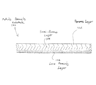
[0037] Figure lA is a schematic cross-sectional view of a multiple porosity
substrate 100 that
constitutes an embodiment of the present invention. The term "multiple- as
used herein
means "more than one," "differential" or "varying." As illustrated in Figure
1A, the substrate
100 has a porous layer 102 on the top surface of the substrate 100, a semi-
porous layer 104 in
the center portion of the substrate 100 and a low porosity layer 106 on the
bottom portion of
the substrate 100. Asphalt roofing materials typically have a top asphalt
layer and a bottom
asphalt layer that are applied over the top and bottom surfaces of the
substrate. The substrate
material typically has a uniform porosity throughout its thickness. For
example, organic felt
substrates, fibrous substrates, fiberglass substrates, polyester substrates
and other polymer-
based substrates such as polypropylene and polyethylene, are formed in layers
or webs that
have a uniform porosity throughout their thickness. The layers or webs absorb
and/or are
impregnated with asphalt which flows into the porous openings in layers or
webs that is
applied to both the top and bottom of the substrate material. In this manner,
the asphalt soaks
into the porous substrate layers and adheres to the substrate layers when the
asphalt cools.
The asphalt is not absorbed by the material itself in the porous layer, but is
absorbed by the
CA 3035791 2019-03-06
7
asphalt flowing into the interstitial openings in the layers of material. The
substrate provides
a structural integrity to the asphalt layers applied to both the top and
bottom of the substrate.
The term "asphalt" as used herein includes modified asphalts that have been
modified with a
variety of additives, including, but not limited to, polymer additives, waxes,
oils, etc., and
fillers such as limestone. In that regard, U.S. Patent 9,637,664, issued May
2, 2017 to
TAMKO Building Products, Inc. entitled "Asphalt Upgrading without Oxidation."
is
specifically incorporated herein by reference for all that it discloses and
teaches. The term
"polyester," as used herein to describe the invention, should be considered to
be only one
example of the various synthetic and polymer-based substrates that can be used
in accordance
with the present invention. The various polyester filaments and polyester webs
may comprise
any polymer-based material, including polymer fibers, nonwoven polymer mats,
woven
polymer mats and polymer fibers made of polypropylene, polyethylene and
similar synthetic
polymers. The term "waterproofing products" includes or comprises roofing
shingles, roll
roofing, waterproof membranes that can be used either above ground or below
ground, or
other similar applications. The term "continuous" refers to the substantially
continuous nature
of some of the polymer fibers and fiberglass threads, as well as other
materials, such as fabric
threads that may be utilized to create the composite substrates disclosed
herein. Fabric is
woven or nonwoven cloth of organic or inorganic filaments, threads or yarns.
Polymer fibers
may be extruded using a spinneret and delivered to a disperser, which places
the
"continuous" polymer fibers in a manner that creates a layer of fibers. Random
interruption in
the filament formation process may occur from time to time, which temporarily
disrupts the
continuous nature of the filaments extruded by the spinneret. The interruption
varies
depending upon the particular day and operating conditions. In other words,
the polymer
filaments rarely break and, in that regard, are considered to be "continuous."
However,
breaks and disruptions in the polymer filaments, as well as fiberglass threads
and fabric
CA 3035791 2019-03-06
8
threads, may occur, but are still considered to be "continuous" even though
the nature of
these fibers and threads is substantially continuous. This is more fully
disclosed in U.S.
Provisional Patent Application No. 62/808,059 filed February 20, 2019,
entitled "Continuous
Nonwoven Polyester Fiber and Fiberglass Thread Hybrid Mat," which is
specifically
incorporated herein by reference for all that it discloses and teaches. The
bottom layer of
asphalt also provides a waterproof seal to the bottom of the porous substrate
layer so that any
water that is proximate to the bottom side of the shingle is not absorbed by
the substrate
layer. Since asphalt is applied to the bottom or back layer of a typical
roofing material, fines
are applied to that asphalt, such as sand, finely ground limestone or other
typical fines
materials. These fines that are applied to the back or bottom layer of the
asphalt prevent the
roofing material from sticking to other roofing material, such as shingles in
a shingle pack,
roll roofing in a roll, etc.
[0038] The multiple porosity substrate 100 illustrated in Figure IA allows for
application of
asphalt on only the top surface, which is absorbed by the porous layer 102,
the semi-porous
layer 104 and portions of the low porosity layer 106. In this manner, only a
top layer of
asphalt is necessary to provide roofing material that is sealed on both the
top and bottom
portions of the multiple porosity substrate 100. The asphalt layer applied to
the top surface of
the multiple porosity substrate 100 seals the top surface. Since the asphalt
applied to the top
layer flows into the interstitial openings in the low porosity layer 106,
water is prevented
from being absorbed into the low porosity layer 106 and the low porosity layer
or water
impervious layer 106 prevents water from penetrating a non-porous layer 106.
In this manner,
asphalt only needs to be applied to the top surface and does not penetrate
through the multiple
porosity substrate 100 so that fines or other protectant material do not have
to be applied to
the back surface of the multiple porosity substrate 100.
CA 3035791 2019-03-06
9
[0039] Figure 1B is a schematic side illustration of a manufacturing line 150
for
manufacturing a multiple porosity substrate. Although Figure IA and Figure 1B
both show a
three-layer substrate, any number of layers of different porosity substrate
materials can be
used. As illustrated in Figure 1B, a supply roll 152 feeds a low porosity
substrate 154 into the
manufacturing line 150. An adhesive applicator 162 applies an adhesive or
other bonding
material to the low porosity or non-porous substrate 154. A supply roll 156 of
semi-porous
substrate 158 feeds the semi-porous substrate 158 to a feeder roller 160. The
feeder roller 160
places the semi-porous substrate 158 over the low porosity or non-porous
substrate 154. The
layers of semi-porous substrate 158 and low porosity or non-porous substrate
154, with a
bonding agent applied, are then fed through compression rollers 164. An
adhesive applicator
172 applies an adhesive or bonding agent to the bonded layers of low porosity
or non-porous
substrate and semi-porous substrate 158. The bonded layers are then fed to
feeder roller 170.
A supply roll 166 of porous substrate 168 feeds the porous substrate material
168 to the
feeder roller 170 which places the porous substrate 168 over the bonded two
layers of semi-
porous substrate 158 and low porosity substrate 154. The three layers then
proceed to
compression rollers 174. The compression rollers 174 bond the three layers of
substrate
material together. The substrate is then transmitted to remaining portions of
the
manufacturing line such as the top coat asphalt coater. Although Figure 1B
illustrates an
example of a manufacturing line for a multiple porosity substrate 150, in
which the low
porosity or impervious substrate 154 is supplied to the system initially, and
other layers are
placed over the low porosity or impervious substrate 154, such as semi-porous
substrate 158
and porous substrate 168, this process can be reversed or changed. For
example, the porous
substrate 168 may be initially fed into the system and the semi-porous
substrate 158 can be
deposited on the porous substrate 168, and then the low porosity or impervious
substrate 154
can be deposited on the semi-porous substrate 158. In other words, the process
illustrated in
CA 3035791 2019-03-06
10
Figure 1B can be inverted so that the various substrate materials are fed into
the system in a
different order. Of course, this is also true for the other manufacturing
processes, such as
those illustrated in Figure 13, Figure 14, Figure 15, Figure 16, Figure 17,
Figure 18 and
Figure 19. With regard to Figure 17, a supply roll of polyester web can be fed
to the system
and fiberglass threads can be deposited on the polyester web by a disperser.
[0040] Figure 2 is a schematic cross-sectional view of a two-layer substrate
having different
porosities. As illustrated in Figure 2, a porous layer 202 is secured to a
very fine or low
porosity layer 204. The two layers can be bonded together using adhesives,
heat bonding,
chemical bonding or other techniques known in the art. An asphalt coater can
then be used to
apply asphalt to the porous layer 202. Alternatively, asphalt can be applied
without the
porous layer 202 being bonded to the very fine porous layer 204 since the
asphalt may
function to bind the layers.
[0041] Figure 3 illustrates a multiple porosity substrate 300. Multiple
porosity substrate 300
has a porous layer 302 and a non-porous layer 304. The porous layer 302 can be
bonded to
the non-porous layer 304 using various methods including heat or the use of
bonding agents.
In addition, the application of asphalt on the porous layer 302 will cause the
asphalt to flow
through the porous layer 302 onto the non-porous layer 304. The asphalt will
function as an
adhesive bond which will bond the porous layer 302 to the non-porous layer
304. The
advantage of the structure illustrated in Figure 3 is that it is simple since
it only has two
layers and does not require application of asphalt on the bottom layer. The
bottom non-
porous layer 304 does not absorb moisture and does not require the application
of fines to
prevent sticking.
100421 Figure 4 is a schematic cross-sectional view of a continuously variable
porosity
substrate 400. As illustrated in Figure 4, the substrate 400 is porous at the
top surface 402 and
non-porous at the bottom surface 404. In between, the porosity varies
substantially
CA 3035791 2019-03-06
11
continuously. The substrate 400 can be manufactured in various different ways
including
various weaving techniques with which fibers of plastic or cloth or other
fibrous materials
can be assembled. For example, very thin fibers can be utilized to create the
non-porous
surface 404 and the thickness of the fibers can increase towards the top
porous surface 402.
The fibers can be secured using various bonding methods including heat,
chemical binding,
and adhesives.
100431 Figure 5 is a cross-sectional view of a multiple porosity substrate
500. As illustrated
in Figure 5, a permeable fiberglass, felt, fiber, polyester, or other polymer
layer 502 can be
connected to an impermeable film layer 504. A bonding layer 506 can be
utilized to bond the
porous layer 502 to the impermeable film layer 504. Again, various bonding
techniques can
be used including heat bonding, chemical bonding, or adhesives utilizing
standard techniques
for securing a permeable layer 502 to the impermeable layer 504.
100441 Figure 6 is a schematic cross-sectional view of a multiple porosity
substrate 600. The
embodiment of Figure 6 is similar to the embodiment of Figure 5 in that a
porous layer
comprising a permeable fiberglass, felt, fiber, polyester, or other polymer
layer 602 is secured
to an impermeable film layer 604 with a bonding layer 608. The difference
between the
embodiments is that perforations 606 are formed in the impermeable film layer
604 which
allows the asphalt that is applied to the permeable layer 602 to seep through
the perforations
606. This further anchors the permeable layer 602 to the impermeable film
layer 604.
100451 Figure 7 is a schematic cross-sectional view of a multiple porosity
substrate 700. As
illustrated in Figure 7, a non-woven polymer fiber 702 is connected to a heat
induced
impermeable layer 704. For example, the multiple porosity substrate 700 may be
formed
from non-woven polyester fibers that are heated on the bottom surface and that
melt to create
a heat induced impermeable layer 704. Other types of materials can be used to
achieve this
same result including polyester, polypropylene, polybutylene, polyimide,
polycarbonate,
CA 3035791 2019-03-06
12
polyamide, polyethylene, polystyrene, polyvinyl chloride, sulfone polymers,
polyvinylidene
chloride, which may be extruded into fibers or provided as a film, and various
composite
layers of these materials. Nylon and other synthetic fibers can also be used.
Some synthetic
polymer materials have low melting temperatures, which could result in
softening or melting
of the synthetic polymer material when immersed in a hot asphalt bath. The
melting
temperatures of the asphalt can be lowered through the use or inclusion of
various waxes in
the asphalt to lower the asphalt melting temperature. This is more fully
disclosed in U.S.
Patent 9,637,664 issued May 2, 2017 to TAMKO Building Products, Inc., entitled
"Asphalt
Upgrading Without Oxidation," which is specifically incorporated herein by
reference for all
that it discloses and teaches. In accordance with that patent, various waxes,
oils, polymers
and other materials can be used to soften asphalt and lower the softening
temperature of the
asphalt. In addition, the manner in which the asphalt is applied to the
substrate can also
reduce the risk of melting the substrate. For example, most processes immerse
the entire
substrate in a bath of hot liquid asphalt so that both sides of the substrate
are coated
simultaneously. This method may tend to melt a substrate material that has a
low melting
temperature, since the immersion of the substrate into a liquid asphalt bath,
which may be at a
very high temperature, can tend to melt fibers made from polymers that have a
low melting
temperature. Alternatively, a temperature controlled asphalt can be sprayed
onto the substrate
and precise amounts of the asphalt can be deposited onto the substrate, which
may lessen the
tendency of the asphalt to melt a low melting temperature polymer. Other
controlled methods
can be used for applying the asphalt. For example, the substrate may be moved
through a
controlled flow curtain of asphalt and the dwell time adjusted for the
substrate to control the
amount of application of the asphalt to the substrate. Other techniques may
also possibly be
used, including extruders, roll applicators, including roll coating, kiss
coating (inking
coating), gravure coating or reverse roll coating, or using a knife/blade
coater. In each of
CA 3035791 2019-03-06
13
these processes, the amount of asphalt, as well as the total amount of heat
that is applied to
the substrate can be controlled, so as to prevent or minimize any melting of
the polymer
fibers.
[0046] Figure 8A is a schematic side view of a system for creating the
substrate illustrated in
the embodiment of Figure 7. As shown in Figure 8A non-woven polymer fiber
sheet 702 is
passed over a heater 704. The heater 704 is sufficiently hot to melt the lower
surface of the
polymer fiber material to create an impermeable layer such as a heat induced
impermeable
layer 704. The non-woven polymer fiber sheet 702 has a continuously constant
speed so that
heat applied by heater 704 is used to melt only the bottom surface of the
substrate 700 to
create the heat induced impermeable layer 704 at the bottom portion of the
substrate 700. In
that regard, the heat generated by heater 704 and the distance from the non-
woven polyester
sheet 702 to the heater 704 can be varied depending upon how fast the non-
woven polymer
fiber sheet 702 is moved over the heater 704, thereby altering the dwell time.
After the heater
704 heats the bottom surface of the non-woven polymer fiber 702, the non-woven
polymer
fiber 702 passes through compression rollers 706 to ensure the heated portion
of the polymer
fibers is compressed. The non-woven polymer fiber web 702 is then passed over
chilled roller
708 to cool the polyester fibers to form an impermeable layer on the bottom
surface of the
substrate 710.
100471 Figure 8B is an alternative embodiment to that shown in Figure 8A. A
non-woven
polymer fiber web 702 is passed through the heater 704, which comprises a
heated roller 710
and an un-heated roller 712, which together, comprise calender rollers. The
heated roller 710
softens the polymer fibers and compresses the softened polymer fibers against
the un-heated
roller 712 to form an impermeable layer at the bottom surface of the non-woven
polymer
fiber web 702. The web is then passed over a chilled roller 714 to cool the
polymers in the
polymer fiber web to form the impermeable layer.
CA 3035791 2019-03-06
14
[0048] Figure 9 is a side cross-sectional view of an embodiment of a multiple
porosity
substrate 900. The multiple porosity substrate 900 comprises a permeable
fiberglass, felt,
fiber, polyester, or other polymer material 902 and an impermeable layer 904
created by a
coating. A coating flows into the interstitial openings in the permeable layer
902 and creates
an impermeable layer 904.
[0049] Figure 10 is a schematic side view of a manufacturing line 908 for the
multiple
porosity substrate 900 illustrated in Figure 9. As shown in Figure 10, the
permeable substrate
902 is fed over rollers so that the bottom portion of the permeable substrate
902 is exposed to
a coater 906. The coater 906 applies the coating to create the impermeable
layer 904 on the
bottom surface of the permeable substrate 902. For example, acrylic, urethane,
silicone and
numerous other similar materials, known to those skilled in the art, can be
used. Hot melt
adhesive, butyl rubber adhesive, polymer modified asphalt adhesive and similar
coatings can
also be used.
[0050] Figure 11 is a bottom view of a permeable substrate 1100 having a
plurality of
impermeable film strips 1104, 1106, 1108, 1110 that are attached to the bottom
surface of the
permeable substrate 1100. The impermeable film strips 1104-1110 have gaps 1102
between
them which allows asphalt to seep through the permeable substrate 1100 to coat
the bottom
surface of the permeable substrate 1100. In this manner, the bottom surface of
the permeable
substrate 1100 can be coated by using asphalt that is applied to just the top
portion of the
permeable substrate 1100. The amount of asphalt that seeps through the gaps
1102 is
controlled by the size of the gaps. Of course, the impermeable film 1104-1110
can be formed
in any desired shape and provide any desired number and size of gaps that are
desired.
[0051] Figure 12 is a schematic side cross-sectional view of a multiple pore
size substrate
1200 that is attached to an impermeable or low permeability layer 1202. As
illustrated in
Figure 12, short fiber fiberglass fibers having a large diameter 1206 form an
upper layer of
CA 3035791 2019-03-06
15
the two pore size substrate 1200. The middle layer is formed from small
diameter cellulose
fibers 1204 that are either short or long fibers. The upper layer 1206 is more
porous than the
middle layer 1204, while the bottom layer 1202 is impermeable or has very low
permeability.
Heated liquid asphalt can be applied to the top layer 1206 which soaks up the
heated asphalt
that flows through the layer 1206 to the layer 1204 and attaches to the
impermeable layer
1202.
100521 Figure 13 is a side schematic view of an embodiment of a manufacturing
line 1300 for
creating a multiple pore size substrate such as illustrated in Figure 12. As
shown in Figure 13,
a supply roll 1302 supplies an impermeable or low permeability sheet 1304 to
the
manufacturing line 1300. A binder applicator 1312 applies a binder to the
impermeable or
low permeable sheet 1304. Supply roll 1302 provides a large diameter short
fiber fiberglass
sheet 1308 to a feeder roller 1310 that places the large diameter short fiber
fiberglass sheet
1308 over the top of the impermeable or low permeability sheet 1304. The
combined sheets
are then passed through compression rollers 1314 which cause the binder from
the binder
applicator 1312 to bind the large diameter short fiber fiberglass sheet 1308
to the
impermeable or low permeability sheet 1304. The combined sheets are then
passed through
compression rollers 1314 to bond the layers together. Binder applicator 1322
applies binder
to the top of the combined sheets. Supply roll 1316 supplies a small diameter
cellulose fiber
sheet 1318 to a feeder roller 1320. Feeder roller 1320 places the small
diameter cellulose
fiber sheet 1318 over the top of the combined sheets and the binders supplied
by the binder
applicator 1322. The combined sheets then proceed to the compression rollers
1324 which
cause the binder from the binder applicator 1322 and the binder applicator
1312 to cause the
sheets to binder together.
100531 Figure 14 is a side schematic diagram of a two pore size substrate
manufacturing line
1400. As illustrated in Figure 14, a supply roll 1402 supplies a cellulose
fiber sheet 1404 to a
CA 3035791 2019-03-06
16
binding applicator 1410. The binding applicator 1410 provides a binder which
may comprise
a chemical binder or adhesive binder. Supply roll 1406 supplies a fiberglass
sheet 1408 to
feeder roller 1411 which places the fiberglass sheet 1408 over the cellulose
fiber sheet 1404.
A binder curing device 1412 is then used to cure the binder provided by binder
applicator
1410. For example, binding curing device 1412 may provide UV light to cure a
UV binder,
an infrared light that heats the binder to cure the binder by heat, a hot air
supply that cures the
binder using heat or other techniques. The binding curing device 1412 may also
produce high
energy radio waves that induce heat to cure the binder provided by the binding
applicator
1410.
100541 Figure 15 is a side schematic view of another embodiment of a
manufacturing line
1500 for a two pore size substrate using asphalt as a binder. As illustrated
in Figure 15, a
supply roll 1502 provides a felt or PET sheet 1504. Supply roll 1506 supplies
a fiberglass
sheet 1508 which is placed over the felt or PET sheet 1504 by feeder roller
1510. The
combined sheets are then passed through an asphalt coating applicator 1512
which applies
asphalt to the top layer, i.e. the fiberglass sheet 1508. The fiberglass sheet
1508 is permeable
and allows the asphalt from the asphalt coating applicator 1512 to penetrate
the fiberglass
sheet 1508 and adhesively bind the fiberglass sheet 1508 to the felt or PET
sheet 1504. In this
manner, the asphalt from the asphalt coating applicator 1512 functions as an
adhesive to bind
the fiberglass sheet 1508 to the felt or PET sheet 1504.
[0055] Figure 16 is side schematic diagram of another embodiment of a
manufacturing line
1602 for manufacturing a combined polyester and fiberglass substrate 1614. As
illustrated in
Figure 16, a polyester filament web 1604, formed from extruded polyester
fibers, is provided
to the manufacturing line 1602. A binding applicator 1606 applies a binding
agent to the
polyester filament web 1604. A supply roll 1608 supplies a fiberglass mat 1610
to nip rollers
1612. The nip rollers place the fiberglass mat 1610 over the top portion of
the polyester
CA 3035791 2019-03-06
17
filament web 1604 so that the fiberglass mat 1610 is secured to the polyester
filament web
1604 by the binder provided by the binder applicator 1606. In this fashion, a
combined
polyester and fiberglass substrate 1614 is created by the manufacturing line
1602.
100561 Figure 17 is a side schematic diagram of another embodiment of a
manufacturing line
1700 for creating a polyester and fiberglass mat substrate. As illustrated in
Figure 17, supply
roll 1702 provides a fiberglass mat 1704 to the manufacturing line 1700. The
fiberglass mat
1704 is placed on a web formation belt 1708. A polyester filament dispenser
1706 is placed
over the fiberglass mat 1704 and the web formation belt 1708 so that the
polyester filaments
from the polyester filament dispenser 1706 can be disbursed over the surface
of the fiberglass
mat 1704. The web formation belt 1708 transfers the fiberglass mat 1704 and
the polyester
filaments that are disbursed on the fiberglass mat 1704 to an entanglement
device 1710. The
entanglement device may include barbed needles that move up and down and cause
the
polyester filaments to become entangled with the fibers from the fiberglass
mat 1704. The
entanglement device may also use a hydroentanglement process in which the
polyester
filaments and fiberglass mat fibers are entangled using high pressure water
jets. The
entangled polyester fibers and fiberglass mat 1712 then proceeds to the
optional heated
calender rollers 1714. The entangled polyester fibers and fiberglass mat 1712
may provide a
substrate for roofing material that has both top and bottom asphalt layers and
is impact
resistant because of the impact resistance of the polyester fibers. This is
disclosed in more
detail in U.S. Patent Application serial number 62/628,141 filed February 8,
2018 by David
Humphreys entitled "Polymat Shingle," which is specifically incorporated
herein by
references for all that it discloses and teaches. The entangled
polyester/fiberglass composite
1712 is fed to the optional heated calender roller 1714 which soften the
polyester filaments so
that the polyester filaments bond with the fiberglass fibers of the fiberglass
mat 1704. In this
manner, the entangled polyester and fiberglass composite 1712 is bound
together. Another
CA 3035791 2019-03-06
18
way of bonding the entangled polyester/fiberglass composite 1712, instead of
using the
optional heated calender roller 1714, is to use an air drum oven 1722. 'The
air drum oven
1722 causes heated air to pass through the entangled polyester/fiberglass
composite 1712 as it
is passed over a perforated oven drum. Bonding may preferably be controlled by
the airflow,
temperature and dwell time of the composite in the oven. Air drum ovens can be
obtained
from American Truetzschler Inc., 12300 Moores Chapel Road, Charlotte, NC
28214.
100571 In some instances, the entangled polyester and fiberglass mat may
be used as a
substrate for asphalt roofing without further bonding. A supply roll 1716 can
optionally be
used, which provides an impermeable film 1718 via a feed roller 1720. The
impermeable film
1718 is placed over the fiberglass mat 1704 and provides an impermeable layer
on the bottom
surface of the entangled polyester and fiberglass composite 1712, so that
heated, liquid
asphalt does not flow through the composite when the heated, liquid asphalt is
poured over
the top of the substrate. Although the impermeable film 1718 is shown as being
applied to the
top of the composite layers and on the fiberglass mat 1704, the impermeable
film 1718 can
also be applied to the bottom composite layer, as illustrated in Figure 18, or
the substrate can
be turned over during manufacturing so that asphalt is applied to what is
shown as the bottom
of the substrate in Figure 17, which is on the top when the substrate is
turned over.
100581 Figure 18 is a schematic side diagram of a composite fiberglass
polymer substrate
manufacturing line 1800. As illustrated in Figure 18, a roller 1802 provides a
polymer
filament web 1804 to the manufacturing line 1800. Simultaneously, supply roll
1806 supplies
a fiberglass mat 1808 to a feed roller 1810. The fiberglass mat 1808 has a
plurality of glass
fibers that form the fiberglass mat 1808. The feed roller 1810 places the
fiberglass mat 1808
over the polymer filament web 1804 so that the fiberglass mat 1808 is aligned
with the
polymer filament web 1804. The fiberglass mat 1808 and the polymer filament
web 1804 are
then fed to an entanglement device 1812. The entanglement device 1812 may
comprise a
CA 3035791 2019-03-06
19
needling device that has a multitude of barbed needles that engage both the
filaments of the
polymer filament web and the fibers of the fiberglass mat 1808 so that the
fiberglass mat
1808 and the polymer filament web 1804 become entangled with one another. The
entanglement device may also use a hydroentanglement process in which the
polyester
filaments and fiberglass mat fibers are entangled using high pressure water
jets. The
entangled web and mat can then, optionally, be fed to heated calender rollers
1814 that both
compress and heat the entangled web and mat to create a composite fiberglass
polymer
substrate 1816. Hydroentanglement devices are available from American
Truetzschler Inc.,
12300 Moores Chapel Road, Charlotte, NC 28214. In some instances, it is not
necessary to
use the heated calender rollers 1814 and the combined entangled fiberglass mat
and polymer
filament web can be used as a substrate for asphalt roofing, without further
bonding. The
optional heated calender rollers 1814 apply sufficient heat and pressure to
soften the polymer
filaments in the polymer filament web 1804 so that the polymer filaments bond
to the
fiberglass fibers to form the composite fiberglass polymer substrate.
[0059] Another way of bonding the entangled polyester/fiberglass composite
1712, instead of
using the optional heated calender roller 1814, is to use an air drum oven
1818. The air drum
oven 1818 causes heated air to pass through the entangled polyester/fiberglass
composite
1712 as it is passed over a perforated oven drum. Bonding may preferably be
controlled by
the airflow, temperature and dwell time of the composite in the oven. Air drum
ovens can be
obtained from American Truetzschler Inc., 12300 Moores Chapel Road, Charlotte,
NC
28214. The fiberglass/polymer substrate 1816 is porous and will absorb asphalt
placed on the
surface of the composite fiberglass polymer substrate 1816 by flowing into the
interstitial
openings in the fiberglass/polymer substrate 1816, and has the advantage of
providing impact
resistance to the roofing material. The fibers of a standard fiberglass
substrate in roofing
material can break and crack when impacted, such as an impact from a hail
stone. This
CA 3035791 2019-03-06
20
weakens the integrity of the roofing material. The addition of the polymer
filaments reduces
the cracking and breaking of the fiberglass fibers since the polymer layers
are able to absorb
the impacts without breaking. Various types of polymers can be used in this
process, as set
forth above, including polypropylene. Polyester is the preferred polymer and
can be extruded
into very fine filaments that can be entangled easily with the fiberglass
fibers. As mentioned
above, various polymer-based substrates can be used, such as polypropylene and
polyethylene, as well as other polymer substrate materials, especially those
that can be
extruded into fine, flexible fibers. Figure 18 also illustrates a supply roll
1818 that can
optionally supply an impermeable film 1820 via the feed roll 1822. The
entangled polymer
filament web and fiberglass mat 1808, as well as the impermeable Film 1820,
can then be fed
to the heated calender rollers 1814 to produce a composite fiberglass polymer
substrate 1816.
With the optional impermeable film 1820, the composite fiberglass polymer
substrate
provides a substrate that does not allow hot liquid asphalt to flow through to
the bottom
surface of the substrate. The various advantages of such a substrate are
disclosed above.
[0060] Figure 19 is a schematic side view illustrating another embodiment of
an apparatus
for making a multi-layer substrate. As illustrated in Figure 19, a supply roll
1902 supplies a
fiberglass mat 1904 to a roller 1906 that moves the fiberglass mat 1904 into
the
manufacturing process illustrated in Figure 19. A supply roll 1908 supplies a
polymer
filament web 1910 that comprise a plurality of entangled polymer filaments.
The polymer
filaments may comprise polyester polymer filaments or other polymer filaments,
such as
indicated above. Feeder roller 1912 places the polymer filament web 1910 over
the fiberglass
mat 1904. The combined fiberglass and polymer filament web 1914 are then moved
to an
entanglement device 1916 that entangles the polymer filaments with the fibers
of the
fiberglass mat 1904 to create the entangled fiberglass and polymer filament
web 1916. The
entangled fiberglass and polymer filament web 1916 is then passed under a
polymer coater
CA 3035791 2019-03-06
21
1918 which places a polymer coating on the entangled fiberglass and polymer
filament web
1916 to create a coated sheet 1920. The coated sheet 1920 is then passed under
a polymer
curing device 1922 that cures the polymer coating in the coated sheet 1920.
The polymer
curer 1922 may comprise a radiant heater, a hot air blower, a UV curing device
or other
curing device for curing the polymer coating on the coated sheet 1920. When
the polymer
coating is cured, a bonded sheet 1924 of substrate material is created.
100611 Figure 20 is a schematic perspective view of a shingle 2000 that may
incorporate the
unique multi-porosity substrates of the present invention. As illustrated in
Figure 20, the
shingle 2000 has a substrate layer 2002 that constitutes one of the various
embodiments of
the multiple porosity substrates disclosed herein. The substrate layer 2002 is
covered on a top
portion by an asphalt layer 2004 and a bottom asphalt layer 2006. The asphalt
layer 2004
includes granules on exposed portions of the shingle 2000 and fines on non-
exposed portions,
such as the headlap region, when the shingle is installed on roofing. The back
of the asphalt
layer 2006 may include fines and adhesive layers, which are typical for
standard asphalt
roofing shingles.
100621 Figure 21 is a schematic perspective view of a laminated shingle 2100
that utilizes the
unique multiple porosity substrates in accordance with the various embodiments
disclosed
herein. As illustrated in Figure 21, an asphalt layer 2102 is disposed on a
substrate layer
2104. The substrate layer 2104 may comprise any one of the multiple porosity
substrates
disclosed herein. Asphalt layer 2106 covers a bottom portion of the substrate
layer 2104. The
bottom layer of the shingle 2100 comprises asphalt layers 2108, 2112 that
cover the substrate
layer 2110 so that the substrate layer 2110 is embedded between the asphalt
layers 2108,
2112. Again, the substrate layer 2110 may comprise any one of the various
embodiments of
the multiple porosity substrates disclosed herein, which would result in
impact resistant
shingles that maintain the structural integrity through impact incidences such
as hail storms.
CA 3035791 2019-03-06
100631 Figure 22 is a side view of a roll roofing product 2200. The roll
roofing 2200 has a
multiple porosity substrate 2202 that can comprise any one of the various
embodiments
disclosed herein. An asphalt layer 2204 is disposed on the top surface of the
substrate 2202
and an asphalt layer 2206 is disposed on a bottom surface of the substrate
2202. Granules
2208 are attached to the top of asphalt layer 2204. Fines 2210 are attached to
the bottom
surface of the asphalt layer 2206. The roll roofing 2200 is similar to other
roll roofing
products with the exception that roll roofing 2200 includes the multiple
porosity substrate
2202 that provides structural integrity and impact resistance to roll roofing
2200.
100641 Figure 23 is a cross-sectional view of a shingle or roll roofing
product 2300 that
utilizes a multiple porosity substrate 2302 that has an impermeable bottom
surface. The
multiple porosity substrate 2302 has a liquid impermeable bottom surface that
does not
require a bottom asphalt layer. For example, the embodiments disclosed in
Figures 1A, 2, 3,
4, 5, 7, 9, and 12 can have an impermeable bottom surface and asphalt can be
applied to the
top surface only. This greatly reduces the complexity and cost of the shingle
or roll roofing
2300 and allows for less complex techniques for making the shingle or roll
roofing 2300. As
illustrated in Figure 23, the asphalt layer 2304 can be applied over the
multiple porosity
substrate 2302 from the top surface of the multiple porosity substrate 2302.
Granules 2306
can then be applied to the top of the asphalt layer 2304 of the shingle or
roll roofing 2300.
100651 Figure 24 is a schematic cross-sectional view of a peel and stick type
of waterproofing
sheet 2400. Again, the peel and stick type of waterproofing sheet 2400 uses a
multiple
porosity substrate 2406 that has an impermeable bottom surface. Again, any one
of the
embodiments illustrated in Figures 1A, 2, 3, 4, 5, 7, 9, and 12 can be
utilized as a multiple
porosity substrate 2406 with those embodiments having a liquid impermeable
bottom or outer
surface. The asphalt layer 2404 is deposited as a liquid on the top surface of
the multiple
porosity substrate 2406 and bonds to the multiple porosity substrate 2406,
since the hot liquid
CA 3035791 2019-03-06
23
asphalt flows into the interstitial openings on the upper portion of the
multiple porosity
substrate 2406, cools and solidifies to form a strong bond between the asphalt
layer 2404 and
the multiple porosity substrate 2406. A release film 2402 is then applied to
the exposed
surface of the asphalt layer 2404. The release film is removed when the peel
and stick
waterproofing sheet 2400 is applied to a surface such as a foundation surface,
roofing surface,
wall surface, etc.
[0066] Consequently, the various embodiments of the present invention provide
various
types of substrates that can be utilized in roofing material that has a single
top asphalt
applicator or that may be used as a substrate for standard roofing materials.
Multiple porosity
layers can be used that allow the top coating asphalt to penetrate the
substrate without
requiring a bottom asphalt applicator. Resulting shingles, waterproofing
materials and roll
goods can be packaged without applying fines to the bottom surface to prevent
shingles from
sticking together in the package or in a roofing embodiment. Non-permeable
bottom layers
can be used to prevent top applied asphalt from flowing through to the bottom
surface. If it is
desirable to have the top coating of asphalt flow through to the bottom
surface, a semi-
permeable layer can be used as a bottom layer of the substrate, or an
impermeable layer can
be used that has perforations or impermeable strips with gaps to control the
amount of asphalt
that flows through to the bottom surface. Polyester filaments can also be
combined with a
fiberglass sheet and entangled to create a combined polyester and fiberglass
substrate that can
be used to create an impact resistant shingle. These substrates can also be
thermobonded
using a perforated air drum roller or through the use of a polymeric coating,
as described
above.
CA 3035791 2019-03-06