Note: Descriptions are shown in the official language in which they were submitted.
INSERTER FOR URETHRAL PLUG
Technical Field
[0001] The present disclosure relates to a device for the insertion into
the urethra
of a urethral plug for controlling or mitigating urinary leakage and the
methods
associated with the use of same.
Background
[0002] Urinary incontinence, or the loss of bladder control, is a common
and
potentially embarrassing problem. Urinary incontinence is not just a medical
problem; it
can affect emotional, psychological and social life. Many people who have
urinary
incontinence are afraid to conduct normal daily activities. The common ways to
deal
with urinary incontinence include collecting systems, absorbent products,
fixed-
occlusion devices, and indwelling catheters.
[0003] Absorbent products (including shields, undergarments, protective
underwear, briefs, diapers, adult diapers, and underpants) are the best known
product
types to manage incontinence. They are generally easy to acquire in pharmacies
or
supermarkets. The disadvantages with absorbent products are that they can be
bulky,
leak, have odors, and can cause skin breakdown.
[0004] Collecting systems typically consist of a sheath worn over the
penis
funneling the urine into a urine bag worn on the leg. These products come in a
variety of
materials and sizes for individual fit. The disadvantages of these products
are that it is
necessary to get measured to ensure proper fit and you need a health care
professional
to write a prescription for them.
[0005] Fixed-occlusion devices (for men) are strapped around the penis,
softly
pressing the urethra and stopping the flow of urine. This management solution
is only
suitable for light or moderate incontinence.
[0006] Indwelling catheters (also known as Foley catheters) are very
often used
in hospital settings or if the user is not able to handle any of the above
solutions. The
indwelling catheter is typically connected to a urine bag that can be worn on
the leg or
hang on the side of the bed. Indwelling catheters need to be changed on a
regular basis
1
Date Recue/Date Received 2020-06-08
CA 03036324 2019-03-08
by a health care professional. The disadvantage, however, is that it is very
common to
get urinary tract infections when using indwelling catheters.
[0007] Intermittent catheters are single use catheters that are inserted
into the
bladder to empty it, and once the bladder is empty they are removed and
discarded.
Intermittent catheters are primarily used for retention (inability to empty
the bladder) but
for some people can be used to reduce/avoid incontinence.
Brief Description of the Drawings
[0008] Embodiments will be readily understood by the following detailed
description in conjunction with the accompanying drawings and the appended
claims.
Embodiments are illustrated by way of example and not by way of limitation in
the
figures of the accompanying drawings.
[0009] FIG. 1A is a perspective view of an inserter for a urethral plug,
in
accordance with disclosed embodiments;
[0010] FIG. 1B is a perspective view of the inserter for a urethral plug
with a
urethral plug coupled thereto, in accordance with disclosed embodiments;
[0011] FIG. 2A is top view of the inserter for a urethral plug, in
accordance with
disclosed embodiments;
[0012] FIG. 2B is back view of the inserter for a urethral plug, in
accordance with
disclosed embodiments;
[0013] FIG. 3 is a side view of the inserter for a urethral plug, in
accordance with
disclosed embodiments;
[0014] FIG. 4 is an end view of the inserter for a urethral plug as viewed
from the
gripping end, in accordance with disclosed embodiments;
[0015] FIG. 5 is an end view of the inserter for a urethral plug as viewed
from the
insertion end, in accordance with disclosed embodiments;
[0016] FIG. 6 is a transparent side view of the inserter for a urethral
plug, in
accordance with disclosed embodiments; and
[0017] FIG. 7 is a side view of the insertion end of the inserter for a
urethral plug,
in accordance with disclosed embodiments.
2
CA 03036324 2019-03-08
Detailed Description of Disclosed Embodiments
[0018] In the following detailed description, reference is made to the
accompanying drawings, which form a part hereof, and in which are shown by way
of
illustration embodiments that may be practiced. It is to be understood that
other
embodiments may be utilized and structural or logical changes may be made
without
departing from the scope. Therefore, the following detailed description is not
to be taken
in a limiting sense, and the scope of embodiments is defined by the appended
claims
and their equivalents.
[0019] Various operations may be described as multiple discrete operations
in
turn, in a manner that may be helpful in understanding embodiments; however,
the
order of description should not be construed to imply that these operations
are order
dependent.
[0020] The description may use perspective-based descriptions such as
up/down, back/front, and top/bottom. Such descriptions are merely used to
facilitate the
discussion and are not intended to restrict the application of disclosed
embodiments.
[0021] The terms "coupled" and "connected," along with their derivatives,
may be
used. It should be understood that these terms are not intended as synonyms
for each
other. Rather, in particular embodiments, "connected" may be used to indicate
that two
or more elements are in direct physical contact with each other. "Coupled" may
mean
that two or more elements are in direct physical contact. However, "coupled"
may also
mean that two or more elements are not in direct contact with each other, but
yet still
cooperate or interact with each other.
[0022] For the purposes of the description, a phrase in the form "A/B" or
in the
form "A and/or B" means (A), (B), or (A and B). For the purposes of the
description, a
phrase in the form "at least one of A, B, and C" means (A), (B), (C), (A and
B), (A and
C), (B and C), or (A, B and C). For the purposes of the description, a phrase
in the form
"(A)B" means (B) or (AB) that is, A is an optional element.
[0023] The description may use the terms "embodiment" or "embodiments,"
which may each refer to one or more of the same or different embodiments.
Furthermore, the terms "comprising," "including," "having," and the like, as
used with
respect to embodiments, are synonymous, and are generally intended as "open"
terms
3
CA 03036324 2019-03-08
(e.g., the term "including" should be interpreted as "including but not
limited to," the term
"having" should be interpreted as "having at least,'' the term "includes"
should be
interpreted as "includes but is not limited to," etc.).
[0024] With respect to the use of any plural and/or singular terms herein,
those
having skill in the art can translate from the plural to the singular and/or
from the
singular to the plural as is appropriate to the context and/or application.
The various
singular/plural permutations may be expressly set forth herein for sake of
clarity.
[0025] Globally, up to 35% of the population over the age of 60 years is
estimated to be incontinent. It has been estimated that twenty-four percent of
older
adults in the U.S. have moderate or severe urinary incontinence that should be
treated
medically. Bladder control problems have been found to be associated with
higher
incidence of many other health problems such as obesity and diabetes.
Difficulty with
bladder control results in higher rates of depression and limited activity
levels.
Incontinence is expensive both to individuals in the form of bladder control
products and
to the health care system and nursing home industry. Injury related to
incontinence is a
leading cause of admission to assisted living and nursing care facilities.
Both women
and men can become incontinent from neurologic injury, congenital
defects, strokes, multiple sclerosis, and physical problems associated with
aging.
[0026] Men tend to experience incontinence less often than women, and the
structure of the male urinary tract accounts for this difference. However,
urinary
incontinence is common in males having undergone prostate cancer treatments,
for
example surgical resection and/or radiation treatment. While urinary
incontinence
affects older men more often than younger men, the onset of incontinence can
happen
at any age. Estimates in the mid-2000s suggested that 17 percent of men over
age 60,
an estimated 600,000 men, experienced urinary incontinence, with this
percentage
increasing with age.
[0027] As disclosed in co-pending U.S. Patent Application No. 15/683,124,
filed
Aug 22, 2017 (concurrently with the present application; Attorney Docket No.
122517-
224848), entitled "Urethral Plug and System for Addressing Urinary
Incontinence," a
urethral plug has been developed that controls or mitigates urinary leakage
associated
with urinary incontinence. The device is configured so that optimally it only
needs to be
4
CA 03036324 2019-03-08
removed for the user to void their bladder. The device is simple in design and
can be
inserted using a disclosed inserter by the user without any assistance from
others.
[0028] Embodiments of the present disclosure relate to a device inserting
a
urethral plug, such as a urethral plug disclosed in co-pending U.S. Patent
Application
No. 15/683,124, filed Aug 22, 2017 (concurrently with the present application;
Attorney
Docket No. 122517-224848), entitled "Urethral Plug and System for Addressing
Urinary
Incontinence." In various embodiments, the urethral plug inserter includes a
proximal
insertion end, a distal gripping end, and a central portion (shaft) disposed
between the
proximal insertion end and the distal gripping end. The main body of the
inserter is
elongate, such as a substantially cylindrical tubular structure, although
other cross-
sectional shapes, such as ovoid, are contemplated. In embodiments, the distal
gripping
end includes protruding ridges on an exterior surface that are configured to
provide a
grip for a user. Placement and/or insertion of the urethral plug inserter is
performed by
gripping the gripping end of the inserter with a urethral plug coupled
thereto, placing the
insertion end at the entrance to the urethra, and pushing the inserter into
the urethra a
desired depth to place the urethral plug in the wearer's urethra. Entry of the
inserter
intro the urethral opening is facilitated by the shape of the urethral plug.
In
embodiments, the urethral plug inserter further includes a central channel
that axially
extends from the proximal insertion end to the distal gripping end and is
configured to
accept a lanyard section of a urethral plug. In embodiments, the central
channel is
generally U shaped with a curved bottom or floor and straight walls extending
from the
bottom. The edges of the central channel may be slightly rounded or chamfered
to aid in
the ease of aligning the urethral plug in the central channel.
[0029] In certain embodiments, the floor of the central channel slopes
upward,
both from the distal gripping end and the proximal insertion end, toward a
middle of the
central portion. As the central channel slopes, the depth of the central
channel is less in
the middle of the central portion than the depth of the central channel at the
distal
gripping end and the proximal insertion end. In embodiments, the slope is
configured
such that a lanyard of the urethral plug creates a smooth, essentially
contiguous surface
with the outer surface of the inserter in the middle of the central portion.
The urethral
plug and the central portion form this essentially contiguous surface for a
length of
CA 03036324 2019-03-08
about 6-12 cm, such as about 8-10 cm. In embodiments, at its shallowest, the
depth of
the channel is about 1-2 mm, whereas the channel is about 3-4 mm at its
deepest
location. This configuration provides comfort as the urethral plug insertion
device, and
urethral plug coupled thereto, are inserted into the urethra of a wearer. This
configuration also facilitates the separation of the urethral plug from the
urethral plug
insertion device once appropriately placed in the urethra.
[0030] In embodiments, the proximal insertion end comprises a tapered
conic
section contiguous with the central channel. This tapered conic section is
configured to
match the contour of, and thereby retain, the urethral plug. This
configuration provides
for enhanced coupling of the urethral plug to the urethral plug insertion
device, for
example, so the urethral plug does not become dislodged during insertion in
the
wearer's urethra. In embodiments, the tapered conic section makes an angle
with
respect to the outside of the urethral plug insertion device from about 25 to
about 35 .
[0031] In embodiments, the distal gripping end includes a urethral plug
stopper
retention system. The urethral plug stopper retention system includes a first
set of
urethral plug location protrusions and a second set of urethral plug location
protrusions
separated by, and disposed on either side of, a urethral plug stopper location
slot. The
configuration provides a groove for a stopper or handle of a urethral plug to
seat. In
combination with the conic section in the insertion end of the device and the
central
channel, the retention system holds the urethral plug in place by application
of a slight
amount of tension to the lanyard portion of the urethral plug. In embodiments,
the first
urethral plug location protrusion protrudes further than the second urethral
plug location
protrusions. In embodiments about 500 +/- 150 grams of force are applied to
pass the
stopper over the first urethral plug location protrusion, and the lanyard is
maintained
under about 300 +/- 100 grams of tension when seated in the central channel.
[0032] In embodiments, the inserter has a smooth outer surface. In certain
embodiments, the inserter has a surface finish designation from about A-2 to
about C-1
as set forth in the SPI guidelines for surface finish, for example the
inserter has a
surface finish designation of A2, A3, B-1, B-2, B-3, or C-1. In a specific
embodiment, the
inserter has a surface finish designation of B-1.
6
CA 03036324 2019-03-08
[0033] In some embodiments, the central portion (shaft) comprises two or
more
depth indicators, configured to provide information about the insertion depth
of the
urethral plug inserter in the urethra of the male subject. The depth
indicators are spaced
on the outside surface of the central portion and may be used by the wearer of
the
urethral plug as a guide for depth placement of the urethral plug.
[0034] In embodiments, the proximal insertion end, the distal gripping
end, and
the central portion comprise a polymer or blend of polymers. In embodiments,
the
inserter comprises a styrene butadiene copolymer (SBC). In specific
embodiments, the
inserted comprises K-Resin . In embodiments, the inserter has an outer surface
comprising a biologically inert material.
[0035] In embodiments, the proximal insertion end, the distal gripping
end, and
the central portion are a unitary body of continuous material, such as formed
by a
molding process or another formation process.
[0036] In embodiments, the inserter is substantially rigid, and does not
bend or
flex during use. Alternatively, a desired amount of flexibility may be
permitted in the
inserter.
[0037] In embodiments, the inserter has a fixed maximum diameter of 3 to
15
mm. In embodiments, the inserter has a fixed maximum length of about 100 to
about
130 mm.
[0038] In embodiments, the inserter may be configured for re-use or may be
configured for single use.
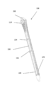
[0039] With reference to FIGS. 1A-1B an exemplary urethral plug insertion
device
100 is provided. FIG. 1A shows a perspective view of a urethral plug insertion
device
100, in accordance with disclosed embodiments. FIG. 1B shows a perspective
view of
the urethral plug insertion device 100 of FIG. 1A with a urethral plug 200
coupled
thereto, in accordance with disclosed embodiments. The urethral plug insertion
device
100 includes a proximal (to the urethra) insertion end 130, a distal gripping
end 110,
and a central portion (shaft) 150 disposed between the proximal insertion end
130 and
the distal gripping end 110.
[0040] The central portion 150 includes depth indicators 154 and 156 as
ridges
on the central portion 150. The depth indicators 154 and 156 are spaced on the
central
7
CA 03036324 2019-03-08
portion 150 and may be used by the wearer of the urethral plug 200 as a guide
for depth
placement of the urethral plug 200. For example, when inserted, the urethral
plug
insertion device 100 may be inserted into the urethra to a depth between depth
indicators 154 and 156 to insure proper placement of the urethral plug 200. By
way of
example, when properly inserted in the urethra, depth indicator 156 may be
inside the
urethra while depth indicator 154 may remain outside the urethra. In
embodiments, 1, 2
or more than 2 depth indicators may be used, while in other embodiments there
may be
no depth indicators.
[0041] The urethral plug insertion device 100 further includes a central
channel
170 running axial from the proximal insertion end 130 to the distal gripping
end 110. The
features of the central channel 170 will be discussed in greater detail below.
[0042] FIG. 2A shows a top view (as viewed facing the central channel 170)
of
the urethral plug insertion device 100, in accordance with disclosed
embodiments. FIG.
2B shows a back view of the urethral plug insertion device 100, in accordance
with
disclosed embodiments. These views show details of the distal gripping end 110
of the
urethral plug insertion device 100, including raised ribs 112 that are
configured to allow
a good grip, such with the thumb and index finger, on the distal gripping end
110 of the
urethral plug insertion device 100.
[0043] FIG. 3 shows a side view of the urethral plug insertion device 100,
in
accordance with disclosed embodiments. In this view, additional features of
the distal
gripping end 110 of the urethral plug insertion device 100 are shown. As shown
in the
view, the distal gripping end 110 includes first urethral plug location
protrusions 114 and
second urethral plug location protrusions 116 separated by, and disposed on
either side
of, a urethral plug location slot 118. The plug location protrusions 114 and
116 and the
urethral plug location slot 118 work in concert to hold a urethral plug (such
as shown in
FIG. 1B) in the correct position for insertion into the urethra of a wearer.
The first
urethral plug location protrusion 114 is located on the side opposite the
central channel
170 while the second urethral plug location protrusions 116 are located on the
side
adjacent to the central channel 170. In addition, the first urethral plug
location protrusion
114 protrudes further than the second urethral plug location protrusions 116.
This works
to bias the release of the urethral plug to the central channel 170 side of
the urethral
8
CA 03036324 2019-03-08
plug insertion device 100. In addition, the low profile of the second urethral
plug location
protrusions 116 facilitates coupling of the urethral plug to the central
channel 170 side of
the urethral plug insertion device 100.
[0044] FIG 4 shows an end view of the urethral plug insertion device 100
as
viewed from the distal gripping end 110, in accordance with disclosed
embodiments. In
this view, the positions of the first urethral plug location protrusion 114,
the second
urethral plug location protrusions 116, and the urethral plug location slot
118 can be
clearly seen. It is also clear that the second urethral plug location
protrusions 116 are
composed of two protrusions on opposite sides of the central channel 170. Also
visible
in this view is the floor 172 of the central channel 170. The floor 172 of the
central
channel 170 is generally U shaped with a round bottom and straight walls
extending
from the bottom. The edges of the central channel 170 may also be slightly
chamfered
to aid in the ease of seeding the urethral plug in to the central channel 170.
An
important feature of the floor 172 of the central channel 170 is also shown.
The floor
172 of the central channel slopes upward from the distal gripping end 110 of
the urethral
plug insertion device 100. This slope is configured such that the lanyard of
the urethral
plug creates a smooth essentially contiguous surface with the urethral plug
insertion
device 100 in the middle of the central portion 150. This configuration
provides comfort
as the urethral plug insertion device 100 and urethral plug coupled thereto is
inserted
into the urethra of a wearer. This configuration also aids in separation of
the urethral
plug from the urethral plug insertion device 100 once appropriately placed in
the
urethra.
[0045] FIG. 5 shows an end view of a urethral plug insertion device 100 as
viewed from the proximal insertion end 130, in accordance with disclosed
embodiments.
Several features of the proximal insertion end 130 can be seen in this view.
Visible in
this view is the floor 172 of the central channel 170. As was shown in FIG. 4,
the floor
172 of the central channel 170 is generally U shaped with a round bottom and
straight
walls extending from the bottom. The edges of the central channel 170 may also
be
slightly chamfered to aid in the ease of seeding the urethral plug in to the
central
channel 170. As with the distal gripping end 110, the floor 172 of the central
channel
slopes upward from the proximal insertion end 110 of the urethral plug
insertion device
9
CA 03036324 2019-03-08
100. Also shown in this view are the plug body coupling taper 174. The
coupling taper
174 is a conic section configured to approximately match the contour of the
plug body of
the urethral plug, such as shown in FIG. 1B. This configuration provides for
enhanced
coupling of the urethral plug to the urethral plug insertion device 100, for
example so the
urethral plug does not become dislodged during insertion in the wearer's
urethra.
[0046] FIG. 6 shows a transparent side view of the urethral plug insertion
device
100, in accordance with disclosed embodiments. In this view the contour of the
floor 172
of the central channel 170 and the coupling taper 174 can be clearly seen. The
floor 172
of the central channel slopes upward from both the proximal insertion end 130
and the
distal gripping end 110 of the urethral plug insertion device 100. This slope
is configured
such that the lanyard of the urethral plug creates a smooth essentially
contiguous
surface with the urethral plug insertion device 100. Also shown in this view
are the plug
body coupling taper 174.
[0047] FIG. 7 shows close up side view of the proximal insertion end 130 of
a
urethral plug insertion device 100. Visible in this view is the floor 172 of
the central
channel 170 which slopes at the proximal end at an angle 4) with respect to
the outside
of the outside urethral plug insertion device 100. The angle 4) is from about
50 to about
, such as about 50, about 6 , about 7 , about 8 , about 9 , or about 10 . Also
shown
Also shown in this view are the plug body coupling taper 174, which makes an
angle 0
with respect to the outside of the outside urethral plug insertion device 100.
The angle 0
is from about 25 to about 35 , such as about 25 , about 26 , about 27 , about
28 ,
about 29 , about 30 , about 310, about 32 , about 33 , about 340, or about 35
.
[0048] Although certain embodiments have been illustrated and described
herein,
it will be appreciated by those of ordinary skill in the art that a wide
variety of alternate
and/or equivalent embodiments or implementations calculated to achieve the
same
purposes may be substituted for the embodiments shown and described without
departing from the scope. Those with skill in the art will readily appreciate
that
embodiments may be implemented in a very wide variety of ways. This
application is
intended to cover any adaptations or variations of the embodiments discussed
herein.
Therefore, it is manifestly intended that embodiments be limited only by the
claims and
the equivalents thereof.