Note: Descriptions are shown in the official language in which they were submitted.
CYCLIC HYBRID INTEGRATED PROCESS UTILIZING STEAM AND SOLVENT
Technical Field
[0001] The present disclosure relates generally to methods of recovering
hydrocarbons, and more specifically to cyclic hybrid integrated processes
utilizing solvent
and other mobilizing fluids.
Background
[0002] This section is intended to introduce various aspects of the art
that may be
associated with the present disclosure. This discussion aims to provide a
framework to
facilitate a better understanding of particular aspects of the present
disclosure.
Accordingly, it should be understood that this section should be read in this
light, and not
necessarily as an admission of prior art.
[0003] Historically commercial in-situ oil sands processes have included:
cyclic
steam stimulation (CSS), steam assisted gravity drainage (SAGD), and steam-
flood (SF).
These processes have extracted oil from underground reservoirs using steam.
The next
generation of in-situ processes may use solvent-steam or pure solvent to
extract oil from
similar reservoirs. The benefits of these processes are lower energy
intensity, lower water
usage, ability to access previously uneconomic resource, and higher reservoir
recovery
rates.
[0004] In steam-based processes, increased temperature lowers the
viscosity of
oil allowing it to flow and be produced. In solvent-based process, the solvent
dilutes the
oil and lowers the viscosity of oil allowing it to flow.
[0005] Steam-based oil sands extraction processes use water sourced from
nearby local supplies to fill central processing facilities (CPF). These
sources of water
may include: surface water, aquifers; freshwater or brackish, and produced
water from
other operations. For steam-based processes, the CPF is generally sized for
the
resources that are available and to bring steam online quickly.
[0006] In contrast, as production or extraction of solvent may not be
possible at the
oil extraction location, solvent generally needs to be transported to site.
Transportation
can be by truck, train, or pipeline. Once the solvent has been brought to
site, a high
- 1 -
CA 3036414 2019-03-12
percentage of solvent (>75%) will be recycled and continuously used in the
solvent
processes. There is a commercial tradeoff with bringing solvent to site. The
supply must
be sized to balance cost, quantity required, and delivery dependability.
Therefore, due to
inability to bring large quantity of solvent to site initially, there will be
a longer time period
for solvent processes to achieve plateau injection rates. This slower ramp to
peak solvent
injection leads to lower oil production and a decrease in economics.
[0007] Previous studies have shown that steam-based process and solvent-
based
processes can target the same resource. However, steam-based processes can
have
inferior performance in solvent specific resources due to thinner pay, lower
bitumen
saturation, and pressure restrictions and/or limitations. One of the primary
reasons is due
to heat losses to non-pay (e.g. cap rock, low bit-sat sands). The performance
downgrade
with steam processes would be more pronounced in mid-to-late life as the steam
chamber
grows. For solvent-based processes, heat in the near wellbore area could
improve
performance.
[0008] Accordingly, there is a need for improved methods of enhancing
cyclic
solvent processes with steam for bitumen recovery from oil sands reservoirs.
Summary
[0009] The present disclosure provides methods of recovering bitumen from
an
underground reservoir penetrated by at least one well. According to at least
one aspect,
the methods include injecting a first mobilizing fluid into the reservoir, the
first mobilizing
fluid having a volume that is less than about 20% by weight of a forecast
injection volume
of fluid to be injected into the reservoir. The methods also include stopping
injecting the
first mobilizing fluid into the reservoir, injecting a first hydrocarbon
solvent into the
reservoir, the first hydrocarbon solvent having a volume equal to a remainder
of the
forecast injection volume of fluid to be injected into the reservoir, shutting
the hydrocarbon
solvent into the reservoir to lower viscosity of at least a portion of the
bitumen in the
reservoir, and recovering bitumen of lowered viscosity from the reservoir.
- 2 -
CA 3036414 2019-03-12
,
[0010] Injecting the first mobilizing fluid into the reservoir may
increase a first
pressure in the reservoir to a second pressure in the reservoir, the second
pressure in
the reservoir being less than about 80% of a lithostatic fracture pressure of
the reservoir.
[0011] Injecting the first mobilizing fluid into the reservoir may
include co-injecting
the first mobilizing fluid and a first flow assurance solvent into the
reservoir.
[0012] The first mobilizing fluid and the first flow assurance
solvent may be mixed
to form a mixture, the mixture comprising between about 5% and 95% of the
first flow
assurance solvent by weight.
[0013] After co-injecting the first mobilizing fluid and the first
flow assurance solvent
into the reservoir, the methods may further include injecting a second
mobilizing fluid into
the reservoir.
[0014] Prior to injecting the first mobilizing fluid into the
reservoir, the methods may
further include injecting a second hydrocarbon solvent into the reservoir,
shutting the
second hydrocarbon solvent into the reservoir to lower viscosity of at least a
portion of
the bitumen in the reservoir, and recovering bitumen of lowered viscosity from
the
reservoir.
[0015] According to at least another aspect, the methods include
injecting a first
portion of a first hydrocarbon solvent into the reservoir, the first portion
having a volume
that is less than a forecast injection volume of fluid to be injected into the
reservoir,
stopping injecting the first portion of the first hydrocarbon solvent into the
reservoir,
injecting a first mobilizing fluid into the reservoir, the first mobilizing
fluid having a volume
that is less than about 20% by weight of the forecast injection volume of
fluid to be injected
into the reservoir, injecting a second portion of the first hydrocarbon
solvent into the
reservoir, the second portion of the first hydrocarbon solvent having a volume
equal to a
remainder of the forecast injection volume of fluid to be injected into the
reservoir, shutting
the hydrocarbon solvent into the reservoir to lower viscosity of at least a
portion of the
bitumen in the reservoir, and recovering bitumen of lowered viscosity from the
reservoir.
[0016] Stopping injecting the first hydrocarbon solvent into the
reservoir may occur
when a pressure in the well increases to a level indicating blocking in the
well.
- 3 -
CA 3036414 2019-03-12
t.
[0017] Injecting the first mobilizing fluid into the reservoir may
increase a first
pressure in the reservoir to a second pressure of the reservoir, the second
pressure in
the reservoir being less than about 80% of a lithostatic fracture pressure of
the reservoir.
[0018] Injecting the first mobilizing fluid into the reservoir may
include co-injecting
the first mobilizing fluid and a first flow assurance solvent into the
reservoir.
[0019] The first mobilizing fluid and the first flow assurance solvent
may be mixed
to form a mixture, the mixture comprising between about 5% and 95% of the
first flow
assurance solvent by weight.
[0020] After co-injecting the first mobilizing fluid and the first flow
assurance solvent
into the reservoir, the methods may further include injecting a second
mobilizing fluid into
the reservoir.
[0021] The present disclosure also provides methods of recovering
bitumen from
an underground reservoir penetrated by at least one well where the at least
one well has
production tubing and casing surrounding the production tubing forming a
spacing
between the production tubing and the casing. According to this aspect, the
methods
include injecting a first hydrocarbon solvent into the reservoir, shutting the
first
hydrocarbon solvent into the reservoir to lower viscosity of at least a
portion of the bitumen
in the reservoir, and recovering bitumen of lowered viscosity from the
reservoir through
the production tubing of the well. During the recovering bitumen of lowered
viscosity from
the reservoir, a first mobilizing fluid is injected into the reservoir through
the spacing
between the casing and the production tubing of the well, the mobilizing fluid
having a
volume that is less than about 20% by weight of a forecast injection volume of
fluid to be
injected into the reservoir.
[0022] According to another aspect, the methods include injecting a
first
hydrocarbon solvent into the reservoir, shutting the hydrocarbon solvent into
the reservoir
to lower viscosity of at least a portion of the bitumen in the reservoir, and
recovering
bitumen of lowered viscosity from the reservoir through the production tubing
of the well.
Prior to recovering the bitumen from the reservoir, a first mobilizing fluid
is injected into
the reservoir down the production tubing of the well, the mobilizing fluid
having a volume
- 4 -
CA 3036414 2019-03-12
,
that is less than about 20% by weight of a forecast injection volume of fluid
to be injected
into the reservoir.
[0023] Injecting the first mobilizing fluid into the reservoir may be
initiated when a
bottom-hole pressure of the well is less than a hydrostatic pressure first
hydrocarbon
solvent and/or a vaporization pressure of the first hydrocarbon solvent.
[0024] A volume of the first mobilizing fluid injected during the
injecting the first
mobilizing fluid into the reservoir may be in a range of about 10% to about
50% of a
volume of bitumen recovered prior to the injecting the first mobilizing fluid
into the
reservoir.
[0025] Injecting the first mobilizing fluid into the reservoir through
the spacing
between the casing and the production tubing of the well may increase a first
pressure in
the reservoir to a second pressure of the reservoir, the second pressure in
the reservoir
being less than about 80% of a lithostatic fracture pressure of the reservoir.
[0026] Injecting the first mobilizing fluid into the reservoir may
include co-injecting
the first mobilizing fluid and a first flow assurance solvent into the
reservoir.
[0027] The first mobilizing fluid and the first flow assurance solvent
may be mixed
to form a mixture, the mixture comprising between about 5% and 95% of the
first flow
assurance solvent by weight.
[0028] After co-injecting the first mobilizing fluid and the first flow
assurance solvent
into the reservoir, the methods may include injecting a second mobilizing
fluid into the
reservoir.
[0029] Prior to injecting the first hydrocarbon solvent into the
reservoir, the
methods may further include injecting a second hydrocarbon solvent into the
reservoir;,
shutting the second hydrocarbon solvent into the reservoir to lower viscosity
of at least a
portion of the bitumen in the reservoir and recovering bitumen of lowered
viscosity from
the reservoir.
[0030] A volume of the first mobilizing fluid injected into the reservoir
may be in a
range of about 5% to about 50% of a volume of bitumen recovered prior to the
injecting
the first mobilizing fluid into the reservoir.
- 5 -
CA 3036414 2019-03-12
,
[0031] Injecting the first mobilizing fluid into the reservoir may
be initiated when a
production rate of the bitumen approaches a pre-determined economic rate.
[0032] Injecting the first mobilizing fluid into the reservoir may
be initiated when a
production rate of bitumen approaches a pre-determined fraction of an initial
production
rate of bitumen.
[0033] Injecting the first mobilizing fluid into the reservoir may
be initiated when a
production volume of fluids from the well approaches a pre-determined fraction
of an
injection volume of fluids into the well.
[0034] Recovering bitumen of lowered viscosity from the reservoir
may have a
duration in a range of between 5 and 20 times a duration of the injecting the
first
hydrocarbon solvent in the reservoir, and injecting the first mobilizing fluid
into the
reservoir is initiated about two-thirds into the duration of the recovering
bitumen of
lowered viscosity from the reservoir.
[0035] A volume of the first mobilizing fluid injected during the
injecting the first
mobilizing fluid into the reservoir may be in a range of about 5% to about 50%
of a volume
of bitumen recovered prior to the injecting the first mobilizing fluid into
the reservoir.
[0036] Injecting the first mobilizing fluid into the reservoir may
include co-injecting
the first mobilizing fluid and a first flow assurance solvent into the
reservoir.
[0037] According to another aspect, a method of recovering bitumen
from an
underground reservoir penetrated by at least one well when a first temperature
and a first
pressure of the reservoir are within a hydrate formation window is described
herein. The
method includes co-injecting a volume of a first mobilizing fluid and a volume
of a first
hydrocarbon solvent into the reservoir to adjust the first temperature of the
reservoir to a
second temperature of the reservoir, the second temperature of the reservoir
being
outside of a hydrate formation window, the volume of the first mobilizing
fluid being less
than about 40% by weight of the volume of the first hydrocarbon solvent. The
method
also includes shutting the first mobilizing fluid and the first hydrocarbon
solvent into the
reservoir to lower viscosity of at least a portion of the bitumen in the
reservoir, and
recovering bitumen of lowered viscosity from the reservoir.
- 6 -
CA 3036414 2019-03-12
[0038] According to any aspect described herein, the first mobilizing
fluid may be
steam.
[0039] According to any aspect described herein, the first mobilizing
fluid may be
water having a temperature greater than about 25 C.
[0040] According to any aspect described herein, the first mobilizing
fluid may be
water having a temperature in a range of about 50 C to about 75 C.
[0041] According to any aspect described herein, the first hydrocarbon
solvent may
comprise at least one of ethane, propane, butane, pentane, and di-methyl
ether.
[0042] According to any aspect described herein, the second hydrocarbon
solvent
may include at least one of ethane, propane, butane, pentane, and di-methyl
ether
[0043] According to any aspect described herein, the first flow assurance
solvent
may have a composition comprising at least 50 mol A. of a viscosity-reducing
component,
based upon total moles in the solvent composition; and at least 5 mol % of a
high-
aromatics component, based upon total moles in the solvent composition;
wherein the
high-aromatics component comprises at least 60 wt. A. aromatics, based upon
total
weight of the high-aromatics component.
[0044] These and other features and advantages of the present application
will
become apparent from the following detailed description taken together with
the
accompanying drawings. However, it should be understood that the detailed
description
and the specific examples, while indicating preferred embodiments of the
application, are
given by way of illustration only, since various changes and modifications
within the spirit
and scope of the application will become apparent to those skilled in the art
from this
detailed description.
Brief Description of the Drawings
[0045] For a better understanding of the various embodiments described
herein,
and to show more clearly how these various embodiments may be carried into
effect,
reference will be made, by way of example, to the accompanying drawings which
show
at least one example embodiment, and which are now described. The drawings are
not
intended to limit the scope of the teachings described herein.
- 7 -
CA 3036414 2020-03-03
[0046] FIG. 1A is a schematic cross sectional view of a underground
reservoir, a
vertical wellbore and a horizontal wellbore showing an example of dispersion
of solvent
and steam from along the horizontal wellbore after integrating solvent-based
injection with
cyclic steam stimulation processes;
[0047] FIG. 1B is a schematic cross sectional view of a underground
reservoir,
vertical wellbore and a horizontal wellbore showing an example of dispersion
of solvent
and steam from along the horizontal wellbore during a cyclic process;
[0048] FIG. 1C is a schematic cross sectional view of a underground
reservoir,
vertical wellbore and a horizontal wellbore showing an example of dispersion
of solvent
and steam from along the horizontal wellbore during a cyclic process;
[0049] FIG. 1D is a schematic cross sectional view of a underground
reservoir,
vertical wellbore and a horizontal wellbore showing an example of dispersion
of solvent
and steam from along the horizontal wellbore during a cyclic process;
[0050] FIG. 2 is a block diagram of a method of recovering bitumen from an
underground reservoir, according to one embodiment;
[0051] FIG. 3 is a block diagram of a method of recovering bitumen from an
underground reservoir, according to another embodiment;
[0052] FIG. 4 is a block diagram of a method of recovering bitumen from an
underground reservoir, according to another embodiment;
[0053] FIG. 5 is a block diagram of a method of recovering bitumen from an
underground reservoir, according to another embodiment; and
[0054] FIG. 6 is a graph comparing reservoir pressure over time for two
extraction
techniques: 1) seven cycles of CSS, and 2) four cycles of CSS followed by
three cycles
of CSP.
[0055] The skilled person in the art will understand that the drawings,
further
described below, are for illustration purposes only. The drawings are not
intended to limit
the scope of the applicant's teachings in any way. Also, it will be
appreciated that for
simplicity and clarity of illustration, elements shown in the figures have not
necessarily
been drawn to scale. For example, the dimensions of some of the elements may
be
- 8 -
CA 3036414 2019-03-12
exaggerated relative to other elements for clarity. Further aspects and
features of the
example embodiments described herein will appear from the following
description taken
together with the accompanying drawings.
Detailed Description
[0056] To promote an understanding of the principles of the disclosure,
reference
will now be made to the features illustrated in the drawings and no limitation
of the scope
of the disclosure is hereby intended. Any alterations and further
modifications, and any
further applications of the principles of the disclosure as described herein
are
contemplated as would normally occur to one skilled in the art to which the
disclosure
relates. For the sake of clarity, some features not relevant to the present
disclosure may
not be shown in the drawings.
[0057] At the outset, for ease of reference, certain terms used in this
application
and their meanings as used in this context are set forth. To the extent a term
used herein
is not defined below, it should be given the broadest definition persons in
the pertinent art
have given that term as reflected in at least one printed publication or
issued patent.
Further, the present techniques are not limited by the usage of the terms
shown below,
as all equivalents, synonyms, new developments, and terms or techniques that
serve the
same or a similar purpose are considered to be within the scope of the present
claims.
[0058] As one of ordinary skill would appreciate, different persons may
refer to the
same feature or component by different names. This document does not intend to
distinguish between components or features that differ in name only. In the
following
description and in the claims, the terms "including" and "comprising" are used
in an open-
ended fashion, and thus, should be interpreted to mean "including, but not
limited to."
[0059] A "hydrocarbon" is an organic compound that primarily includes the
elements of hydrogen and carbon, although nitrogen, sulfur, oxygen, metals, or
any
number of other elements may be present in small amounts. Hydrocarbons
generally
refer to components found in heavy oil or in oil sands. Hydrocarbon compounds
may be
aliphatic or aromatic, and may be straight chained, branched, or partially or
fully cyclic.
- 9 -
CA 3036414 2019-03-12
[0060] A "light hydrocarbon" is a hydrocarbon having carbon numbers in a
range
from 1 to 9.
[0061] "Bitumen" is a naturally occurring heavy oil material. Generally, it
is the
hydrocarbon component found in oil sands. Bitumen can vary in composition
depending
upon the degree of loss of more volatile components. It can vary from a very
viscous,
tar-like, semi-solid material to solid forms. The hydrocarbon types found in
bitumen can
include aliphatics, aromatics, resins, and asphaltenes. A typical bitumen
might be
composed of:
¨ 19 weight (wt.) percent (%) aliphatics (which can range from 5 wt. % to
30 wt. %
or higher);
¨ 19 wt. % asphaltenes (which can range from 5 wt. % to 30 wt. % or
higher);
¨ 30 wt. % aromatics (which can range from 15 wt. % to 50 wt. % or higher);
¨ 32 wt. % resins (which can range from 15 wt. % to 50 wt. % or higher);
and
¨ some amount of sulfur (which can range in excess of 7 wt. %), based on
the total
bitumen weight.
[0062] In addition, bitumen can contain some water and nitrogen compounds
ranging from less than 0.4 wt. % to in excess of 0.7 wt. %. The percentage of
the
hydrocarbon found in bitumen can vary. The term "heavy oil" includes bitumen
as well as
lighter materials that may be found in a sand or carbonate reservoir.
[0063] "Heavy oil" includes oils which are classified by the American
Petroleum
Institute ("API"), as heavy oils, extra heavy oils, or bitumens. The term
"heavy oil" includes
bitumen. Heavy oil may have a viscosity of about 1,000 centipoise (cP) or
more, 10,000
cP or more, 100,000 cP or more, or 1,000,000 cP or more. In general, a heavy
oil has an
API gravity between 22.3 API (density of 920 kilograms per meter cubed
(kg/m3) or 0.920
grams per centimeter cubed (g/cm3)) and 10.0 API (density of 1,000 kg/m3 or 1
g/cm3).
An extra heavy oil, in general, has an API gravity of less than 10.0 API
(density greater
than 1,000 kg/m3 or 1 g/cm3). For example, a source of heavy oil includes oil
sand or
bituminous sand, which is a combination of clay, sand, water and bitumen.
[0064] The term "viscous oil" as used herein means a hydrocarbon, or
mixture of
hydrocarbons, that occurs naturally and that has a viscosity of at least 10 cP
at initial
- 10 -
CA 3036414 2019-03-12
=
reservoir conditions. Viscous oil includes oils generally defined as "heavy
oil" or
"bitumen." Bitumen is classified as an extra heavy oil, with an API gravity of
about 100 or
less, referring to its gravity as measured in degrees on the API Scale. Heavy
oil has an
API gravity in the range of about 22.3 to about 100. The terms viscous oil,
heavy oil, and
bitumen are used interchangeably herein since they may be extracted using
similar
processes.
[0065] In-situ is a Latin phrase for "in the place" and, in the
context of hydrocarbon
recovery, refers generally to a subsurface hydrocarbon-bearing reservoir. For
example,
in-situ temperature means the temperature within the reservoir. In another
usage, an in-
situ oil recovery technique is one that recovers oil from a reservoir within
the earth.
[0066] The term "subterranean formation" refers to the material
existing below the
Earth's surface. The subterranean formation may comprise a range of
components, e.g.
minerals such as quartz, siliceous materials such as sand and clays, as well
as the oil
and/or gas that is extracted. The subterranean formation may be a subterranean
body of
rock that is distinct and continuous. The terms "reservoir" and "formation"
may be used
interchangeably.
[0067] The term "wellbore" as used herein means a hole in the
subsurface made
by drilling or inserting a conduit into the subsurface. A wellbore may have a
substantially
circular cross section or any other cross-sectional shape. The term "well,"
when referring
to an opening in the formation, may be used interchangeably with the term
"wellbore."
[0068] The term "cyclic process" refers to an oil recovery technique
in which the
injection of a viscosity reducing agent into a wellbore to stimulate
displacement of the oil
alternates with oil production from the same wellbore and the injection-
production process
is repeated at least once. Cyclic processes for heavy oil recovery may include
a cyclic
steam stimulation (CSS) process, a liquid addition to steam for enhancing
recovery
(LASER) process, a cyclic solvent process (CSP), or any combination thereof.
[0069] The term "forecast injection volume" as used herein means an
anticipated
or expected volume of a fluid to be injected into the reservoir.
- 1 1 -
CA 3036414 2019-03-12
=
[0070] The term "lithostatic fracture pressure" as used herein means a
pressure at
which the rock above the reservoir (overburden) fractures. The lithostatic
fracture
pressure is the relationship between depth and increasing stress required to
fracture/fail
rock. The deeper a well, the higher the stress required to fail rock.
[0071] The articles "the," "a" and "an" are not necessarily limited to
mean only one,
but rather are inclusive and open ended to include, optionally, multiple such
elements.
[0072] As used herein, the terms "approximately," "about,"
"substantially," and
similar terms are intended to have a broad meaning in harmony with the common
and
accepted usage by those of ordinary skill in the art to which the subject
matter of this
disclosure pertains. It should be understood by those of skill in the art who
review this
disclosure that these terms are intended to allow a description of certain
features
described and claimed without restricting the scope of these features to the
precise
numeral ranges provided. Accordingly, these terms should be interpreted as
indicating
that insubstantial or inconsequential modifications or alterations of the
subject matter
described and are considered to be within the scope of the disclosure.
[0073] "At least one," in reference to a list of one or more entities
should be
understood to mean at least one entity selected from any one or more of the
entity in the
list of entities, but not necessarily including at least one of each and every
entity
specifically listed within the list of entities and not excluding any
combinations of entities
in the list of entities. This definition also allows that entities may
optionally be present
other than the entities specifically identified within the list of entities to
which the phrase
"at least one" refers, whether related or unrelated to those entities
specifically identified.
Thus, as a non-limiting example, "at least one of A and B" (or, equivalently,
"at least one
of A or B," or, equivalently "at least one of A and/or B") may refer, to at
least one, optionally
including more than one, A, with no B present (and optionally including
entities other than
B); to at least one, optionally including more than one, B, with no A present
(and optionally
including entities other than A); to at least one, optionally including more
than one, A, and
at least one, optionally including more than one, B (and optionally including
other entities).
In other words, the phrases "at least one," "one or more," and "and/or" are
open-ended
expressions that are both conjunctive and disjunctive in operation. For
example, each of
- 12 -
CA 3036414 2019-03-12
the expressions "at least one of A, B and C," "at least one of A, B, or C,"
"one or more of
A, 6, and C," "one or more of A, 6, or C" and "A, B, and/or C" may mean A
alone, B alone,
C alone, A and B together, A and C together, B and C together, A, B and C
together, and
optionally any of the above in combination with at least one other entity.
[0074] Where two or more ranges are used, such as but not limited to 1 to
5 or 2
to 4, any number between or inclusive of these ranges is implied.
[0075] As used herein, the phrases "for example," "as an example," and/or
simply
the terms "example" or "exemplary," when used with reference to one or more
components, features, details, structures, methods and/or figures according to
the
present disclosure, are intended to convey that the described component,
feature, detail,
structure, method and/or figure is an illustrative, non-exclusive example of
components,
features, details, structures, methods and/or figures according to the present
disclosure.
Thus, the described component, feature, detail, structure, method and/or
figure is not
intended to be limiting, required, or exclusive/exhaustive; and other
components,
features, details, structures, methods and/or figures, including structurally
and/or
functionally similar and/or equivalent components, features, details,
structures, methods
and/or figures, are also within the scope of the present disclosure. Any
embodiment or
aspect described herein as "exemplary" is not to be construed as preferred or
advantageous over other embodiments.
[0076] In spite of the technologies that have been developed, there
remains a need
in the field for methods of enhancing the recovery of bitumen.
[0077] Various approaches of enhancing solvent-based extraction processes
with
the addition of steam are described herein. The proposed approaches involve
utilizing
and integrating different steam processes and recovery mechanisms at different
stages
of solvent-based extraction processes to enhance the bitumen recovery from a
reservoir.
[0078] Referring now to Figures 1A to 1D, illustrated therein are
schematic cross
sectional views of an underground reservoir, a vertical wellbore and a
horizontal wellbore
showing an example of dispersion of solvent and steam along the horizontal
wellbore
after integrating cyclic solvent processes (CSPs) with cyclic steam
stimulation processes
(CSSs).
- 13 -
CA 3036414 2019-03-12
[0079] For instance, FIG. 1A shows a schematic cross sectional view of an
underground reservoir 100, a vertical wellbore 102 and a horizontal wellbore
104 showing
an example of dispersion of solvent and steam along the horizontal wellbore
after
performing a single cycle of a CSS after 2 cycles of a CSP.
[0080] FIG. 1B is a schematic cross sectional view of an underground
reservoir
110, a vertical wellbore 112 and a horizontal wellbore 114 showing an example
of
dispersion of solvent and steam along the horizontal wellbore after performing
two cycles
of a CSP after a single cycle of CSS and before n-3 cycles of the CSS.
[0081] FIG. 1C is a schematic cross sectional view of an underground
reservoir
120, a vertical wellbore 122 and a horizontal wellbore 124 showing an example
of
dispersion of solvent and steam along the horizontal wellbore after performing
two cycles
of a CSS after a single cycle of a CSP and before n-3 cycles of the CSP.
[0082] FIG. 1D is a schematic cross sectional view of an underground
reservoir
130, a vertical wellbore 132 and a horizontal wellbore 134 showing an example
of
dispersion of solvent and steam along the horizontal wellbore after two cycles
of CSS
followed by n-2 cycles of a CSP.
[0083] In the aforementioned CSPs, solvents may be used to enhance the
extraction of petroleum products from the reservoir. For instance, the solvent
may be a
light hydrocarbon, a mixture of light hydrocarbons or dimethyl ether. In other
embodiments, the solvent may be a C2-C7 alkane, a C2-C7 n-alkane, an n-
pentane, an
n-heptane, or a gas plant condensate comprising alkanes, naphthenes, and
aromatics.
[0084] In other embodiments, the solvent may be a light, but condensable,
hydrocarbon or mixture of hydrocarbons comprising ethane, propane, butane, or
pentane.
The solvent may comprise at least one of ethane, propane, butane, pentane, and
carbon
dioxide. The solvent may comprise greater than 50 mol% C2-05 hydrocarbons on a
mass
basis. The solvent may be greater than 50 mol% propane, optionally with
diluent when it
is desirable to adjust the properties of the injectant to improve performance.
[0085] Additional injectants may include CO2, natural gas, C5+
hydrocarbons,
ketones, and alcohols. Non-solvent injectants that are co-injected with the
solvent may
- 14 -
CA 3036414 2019-03-12
include steam, non-condensable gas, or hydrate inhibitors. The solvent
composition may
comprise at least one of diesel, viscous oil, natural gas, bitumen, diluent,
C5+
hydrocarbons, ketones, alcohols, non-condensable gas, water, biodegradable
solid
particles, salt, water soluble solid particles, and solvent soluble solid
particles.
[0086] To
reach a desired injection pressure of the solvent composition, a
viscosifier may be used in conjunction with the solvent. The viscosifier may
be useful in
adjusting solvent viscosity to reach desired injection pressures at available
pump rates.
The viscosifier may include diesel, viscous oil, bitumen, and/or diluent. The
viscosifier
may be in the liquid, gas, or solid phase. The viscosifier may be soluble in
either one of
the components of the injected solvent and water. The viscosifier may
transition to the
liquid phase in the reservoir before or during production. In the liquid
phase, the
viscosifiers are less likely to increase the viscosity of the produced fluids
and/or decrease
the effective permeability of the formation to the produced fluids.
[0087] The
solvent composition may comprise (i) a polar component, the polar
component being a compound comprising a non-terminal carbonyl group; and (ii)
a non-
polar component, the non-polar component being a substantially aliphatic
substantially
non-halogenated alkane. The solvent composition may have a Hansen hydrogen
bonding parameter of 0.3 to 1.7 (or 0.7 to 1.4). The solvent composition may
have a
volume ratio of the polar component to non-polar component of 10:90 to 50:50
(or 10:90
to 24:76, 20:80 to 40:60, 25:75 to 35:65, or 29:71 to 31:69). The polar
component may
be, for instance, a ketone or acetone. The non-polar component may be, for
instance, a
C2-C7 alkane, a C2-C7 n-alkane, an n-pentane, an n-heptane, or a gas plant
condensate
comprising alkanes, naphthenes, and aromatics. For further details and
explanation of
the Hansen Solubility Parameter System see, for example, Hansen, C. M. and
Beerbower, Kirk-Othmer, Encyclopedia of Chemical Technology, (Suppl. Vol. 2nd
Ed),
1971, pp 889-910 and "Hansen Solubility Parameters A User's Handbook" by
Charles
Hansen, CRC Press, 1999.
[0088] The
solvent composition may comprise (i) an ether with 2 to 8 carbon
atoms; and (ii) a non-polar hydrocarbon with 2 to 30 carbon atoms. Ether may
have 2 to
8 carbon atoms. Ether may be di-methyl ether, methyl ethyl ether, di-ethyl
ether, methyl
- 15 -
CA 3036414 2019-03-12
iso-propyl ether, methyl propyl ether, di-isopropyl ether, di-propyl ether,
methyl iso-butyl
ether, methyl butyl ether, ethyl iso-butyl ether, ethyl butyl ether, iso-
propyl butyl ether,
propyl butyl ether, di-isobutyl ether, or di-butyl ether. Ether may be di-
methyl ether. The
non-polar hydrocarbon may a C2-C30 alkane. The non-polar hydrocarbon may be a
C2-
05 alkane. The non-polar hydrocarbon may be propane. The ether may be di-
methyl
ether and the hydrocarbon may be propane. The volume ratio of ether to non-
polar
hydrocarbon may be 10:90 to 90:10; 20:80 to 70:30; or 22.5:77.5 to 50:50.
[0089] The solvent composition may comprise at least 5 mol % of a high-
aromatics
component (based upon total moles of the solvent composition) comprising at
least 60
wt. % aromatics (based upon total mass of the high-aromatics component). One
suitable
and inexpensive high-aromatics component is gas oil from a catalytic cracker
of a
hydrocarbon refining process, also known as a light catalytic gas oil (LCGO).
[0090] In some embodiments, different steam processes and recovery
mechanisms can be integrated with solvent-based extraction processes by
initiating the
steam processes prior to a first cycle of a solvent-based extraction process.
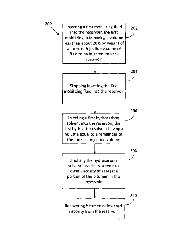
[0091] Referring now to FIG. 2, illustrated therein is a method 200 of
recovering
bitumen from an underground reservoir penetrated by at least one well. The
method 200
includes at a step 202, injecting a first mobilizing fluid into the reservoir.
The first
mobilizing fluid may be a solvent mixed with steam, or pure steam or water
having a
temperature above about 25 C. In some embodiments, the first mobilizing fluid
may have
a temperature in a range of about 50 C to about 75 C. In embodiments where
the
mobilizing fluid includes a solvent, the solvent can be any solvent described
above with
respect to the solvents that can be used during the solvent-based extraction
processes.
[0092] At step 202, the volume of the first mobilizing fluid that is
injected into the
reservoir is less than about 20% by weight of a forecast injection volume of
fluid to be
injected into the reservoir. Herein, the term "forecast injection volume"
refers to an expect
volume of fluid to be injected into the reservoir during a single cycle of a
CSP.
[0093] The method 200 also includes at a step 204 stopping the injection
of the
first mobilizing fluid into the reservoir.
- 16 -
CA 3036414 2019-03-12
[0094] At a step 206, a first hydrocarbon solvent is injected into the
reservoir. The
first hydrocarbon solvent has a volume equal to a remainder of the forecast
injection
volume of fluid to be injected into the reservoir. The first hydrocarbon
solvent may be a
liquid or vapor solvent or a solvent mixed with steam. The first hydrocarbon
solvent can
be any solvent described above with respect to the solvents that can be used
during the
solvent-based extraction processes.
[0095] At a step 208, the first hydrocarbon solvent is shut into the
reservoir to lower
viscosity of at least a portion of the bitumen in the reservoir. Herein, the
first hydrocarbon
solvent is shut into the reservoir when the reservoir is capable of producing
bitumen but
is not producing bitumen.
[0096] At a step 210, bitumen of lowered viscosity is recovered from the
reservoir.
[0097] In some embodiments, injecting the first mobilizing fluid into the
reservoir
increases a first pressure in the reservoir to a second pressure of the
reservoir. In some
embodiments, the second pressure in the reservoir may be less than about 80%
of a
lithostatic fracture pressure of the reservoir.
[0098] In some embodiments, injecting the first mobilizing fluid into the
reservoir
may include co-injecting the first mobilizing fluid and a first flow assurance
solvent into
the reservoir. Herein, co-injecting may include injecting one or more
sequential slugs of
the first mobilizing fluid and the first flow assurance solvent into the
reservoir. For
instance, co-injecting the first mobilizing fluid and a first flow assurance
solvent into the
reservoir may include injecting 10 m3 of pure flow assurance solvent, for
example,
followed by injecting 10 m3 of a first mobilizing fluid (e.g. pure water or
steam), for
example.
[0099] In some embodiments, the flow assurance solvent may be a light
catalytic
gas oil (LCGO). In some embodiments, the flow assurance solvent may comprise
at least
50 mol % of a viscosity-reducing component, based upon total moles in the
solvent
composition, and at least 5 mol % of a high-aromatics component, based upon
total moles
in the solvent composition, wherein the high-aromatics component comprises at
least 60
wt. % aromatics, based upon total weight of the high-aromatics component.
- 17 -
CA 3036414 2019-03-12
= ,
[0100] In some embodiments, the first mobilizing fluid and the first
flow assurance
solvent may be mixed to form a mixture, the mixture comprising between about
5% and
95% of the first flow assurance solvent by weight.
[0101] In some embodiments, the method 200 may also include, after co-
injecting
the first mobilizing fluid and the first flow assurance solvent into the
reservoir, injecting a
second mobilizing fluid into the reservoir. The second mobilizing fluid may be
a solvent
mixed with steam, or pure steam or water.
[0102] In some embodiments, the method 200 may also include, prior to
injecting
the first mobilizing fluid into the reservoir, injecting a second hydrocarbon
solvent into the
reservoir, shutting the second hydrocarbon solvent into the reservoir to lower
viscosity of
at least a portion of the bitumen in the reservoir; and recovering bitumen of
lowered
viscosity from the reservoir.
[0103] In some embodiments, different steam processes and recovery
mechanisms can be integrated with solvent-based extraction processes by
initiating the
steam processes during to an injection cycle of a solvent-based extraction
process.
[0104] Referring now to FIG. 3, illustrated therein is a method 300 of
recovering
bitumen from an underground reservoir penetrated by at least one well. The
method 300
includes at a step 302 injecting a first portion of a first hydrocarbon
solvent into the
reservoir. Again, the first hydrocarbon solvent may be a liquid or vapor
solvent or a solvent
mixed with steam. The first hydrocarbon solvent can be any solvent described
above with
respect to the solvents that can be used during the solvent-based extraction
processes.
The first portion has a volume that is less than a forecast injection volume
of fluid to be
injected into the reservoir.
[0105] At a step 304, injecting first hydrocarbon solvent into the
reservoir is
stopped. In some embodiments, injecting the first hydrocarbon solvent into the
reservoir
is stopped when a pressure in the well increases to a level indicating
blocking in the well.
For instance, blocking in the well may be indicated by comparing a bottom hole
pressure
in the injection well to a reservoir pressure seen by an observation well or
an adjacent
production well. If the injection well has a significantly higher pressure
than the reservoir
- 18 -
CA 3036414 2019-03-12
. ,
,
well, that could indicate blockage in the injection well. The blockage would
generally be
suspected or seen in two or three days.
[0106] For example, during injection, the bottom hole pressure of
the injector well
and the observed pressure in the reservoir (other than first injection cycle)
may be within
a preselected pressure range. If the difference between the bottom hole
pressure of the
injector well and the observed pressure in the reservoir is greater than 40%
for more than
two, days that could be indicative of plugging.
[0107] At a step 306, a first mobilizing fluid is injected into the
reservoir. The first
mobilizing fluid has a volume that is less than about 20% by weight of the
forecast
injection volume of fluid to be injected into the reservoir. In some
embodiments, injecting
the first mobilizing fluid into the reservoir at step 306 may increase a first
pressure in the
reservoir to a second pressure of the reservoir, the second pressure in the
reservoir being
less than about 80% of a lithostatic fracture pressure of the reservoir. In
some
embodiments, injecting the first mobilizing fluid into the reservoir at step
306 may include
co-injecting the first mobilizing fluid and a first flow assurance solvent
into the reservoir.
In some embodiments, the first mobilizing fluid and the first flow assurance
solvent may
be mixed to form a mixture, the mixture comprising between about 5% and 95% of
the
first flow assurance solvent by weight.
[0108] At a step 308, a second portion of the first hydrocarbon
solvent is injected
into the reservoir. The second portion of the first hydrocarbon solvent has a
volume equal
to a remainder of the forecast injection volume of fluid to be injected into
the reservoir. In
some embodiments, the second portion of the forecast injection volume is in a
range of
about 3% to about 20% by weight, or in a range of about 5% to about 15% by
weight, or
about 10% by weight of the forecast injection volume.
[0109] At a step 310, the first hydrocarbon solvent is shut into
the reservoir to lower
viscosity of at least a portion of the bitumen in the reservoir. At step 312,
the bitumen of
lowered viscosity is recovered from the reservoir.
[0110] In some embodiments, after co-injecting the first mobilizing
fluid and the first
flow assurance solvent into the reservoir at step 306, a second mobilizing
fluid may be
injected into the reservoir.
- 19 -
CA 3036414 2019-03-12
[0111] In some embodiments, different steam processes and recovery
mechanisms can be integrated with solvent-based extraction processes by
initiating the
steam processes during a production cycle of a solvent-based extraction
process.
[0112] Referring now to FIG. 4, illustrated therein is a method 400 of
recovering
bitumen from an underground reservoir penetrated by at least one well. In this
method,
the at least one well generally includes production tubing and casing
surrounding the
production tubing forming a spacing between the production tubing and the
casing.
[0113] The method 400 includes at a step 402 injecting a forecast
injection volume
of a first hydrocarbon solvent into the reservoir. At a step 404, the
hydrocarbon solvent is
shut into the reservoir to lower viscosity of at least a portion of the
bitumen in the reservoir.
At a step 406, bitumen of lowered viscosity is recovered from the reservoir
through the
production tubing of the well.
[0114] In some embodiments, during the recovery of bitumen from the
reservoir, a
first mobilizing fluid may be injected into the reservoir. In some
embodiments, the first
mobilizing fluid may be injected through the spacing between the casing and
the
production tubing of the well. In other embodiments, the first mobilizing
fluid may be
injected directly down the production tubing. When the first mobilizing fluid
is injected
down the casing, production of bitumen may continue. When the first mobilizing
fluid is
injected down the tubing, production of bitumen is generally halted. Injection
pressures of
the first mobilizing fluid are generally the same when the mobilizing fluid is
injected down
the tubing into the wellbore and/or reservoir when compared to when the first
mobilizing
fluid is injected down the casing into the wellbore and/or reservoir.
[0115] In these embodiments, the method 400 includes a step of stopping
the
production of the bitumen of lowered viscosity and a step of injecting the
first mobilizing
fluid directly down the production tubing. The mobilizing fluid may have a
volume that is
less than about 20% by weight of a forecast injection volume of a first
hydrocarbon solvent
to be injected into the reservoir.
[0116] In some embodiments, the step 402 of injecting the first mobilizing
fluid into
the reservoir may be initiated when a bottom-hole pressure of the well is less
than a
hydrostatic pressure of the first hydrocarbon solvent and/or a vaporization
pressure of the
- 20 -
CA 3036414 2019-03-12
. ,
first hydrocarbon solvent. It should be noted that hydrostatic pressure is
generally the
pressure that a fluid will flow to a surface without assistance of a pump or
any form of
artificial lift.
[0117] In some embodiments, the volume of the first mobilizing fluid
injected during
the step 402 of injecting the first mobilizing fluid into the reservoir is in
a range of about
10% to about 50% of a volume of bitumen recovered prior to the injecting the
first
mobilizing fluid into the reservoir.
[0118] In some embodiments, injecting the first mobilizing fluid into
the reservoir
through the spacing between the casing and the production tubing of the well
may
increase a first pressure in the reservoir to a second pressure of the
reservoir, the second
pressure of the reservoir being less than about 80% of a lithostatic fracture
pressure of
the reservoir.
[0119] In some embodiments, injecting the first mobilizing fluid into
the reservoir
includes co-injecting the first mobilizing fluid and a first flow assurance
solvent into the
reservoir.
[0120] In some embodiments, the first mobilizing fluid and the first
flow assurance
solvent are mixed to form a mixture, the mixture comprising between about 5%
and 95%
of the first flow assurance solvent by weight.
[0121] In some embodiments, after co-injecting the first mobilizing
fluid and the first
flow assurance solvent into the reservoir, injecting a second mobilizing fluid
into the
reservoir.
[0122] In some embodiments, different steam processes and recovery
mechanisms can be integrated with solvent-based extraction processes by
initiating the
steam processes during a production cycle outside of completion of a solvent-
based
extraction process.
[0123] For instance, the method 400 may further include a step of, prior
to injecting
a forecast injection volume of the first hydrocarbon solvent into the
reservoir, injecting a
second hydrocarbon solvent into the reservoir, a step of shutting the second
hydrocarbon
solvent into the reservoir to lower the viscosity of at least a portion of the
bitumen in the
- 21 -
CA 3036414 2019-03-12
, .
reservoir; and a step of recovering bitumen of lowered viscosity from the
reservoir. The
second hydrocarbon solvent may be the same as the first hydrocarbon solvent or
may be
different from the first hydrocarbon solvent.
[0124] Injecting the first mobilizing fluid into the reservoir may
be initiated when a
bottom-hole pressure of the well is less than a hydrostatic pressure first
hydrocarbon
solvent and/or a vaporization pressure of the first hydrocarbon solvent.
[0125] The volume of the first mobilizing fluid injected into the
reservoir may be in
a range of about 5% to about 50% of the volume of bitumen recovered prior to
the injecting
the first mobilizing fluid into the reservoir.
[0126] Injecting the first mobilizing fluid into the reservoir
through the spacing
between the casing and the production tubing or directly down the production
tubing may
increase a first pressure in the reservoir to a second pressure of the
reservoir, the second
pressure in the reservoir being less than about 80% of a lithostatic fracture
pressure of
the reservoir.
[0127] In some embodiments, the steam processes may be initiated at
the end of
a production cycle of a solvent-based extraction process to enhance recovery
of bitumen
during the solvent-based extraction process.
[0128] For instance, method 400 may include injecting the first
mobilizing fluid into
the reservoir when a production rate of the bitumen approaches a pre-
determined
economic rate.
[0129] For instance, method 400 may include injecting the first
mobilizing fluid into
the reservoir when a production rate of the bitumen approaches a pre-
determined fraction
of an initial production rate of bitumen. For example, method 400 may include
injecting
the first mobilizing fluid into the reservoir when a production rate of the
bitumen
approaches one-third of an initial total fluid production rate (e.g. after a
first injection
cycle), where the initial total fluid production rate includes a total initial
production rate of
water, solvent, bitumen and gas produced up a casing gas system. In some
embodiments, the initial total fluid production rate may be achieved using
artificial lift or
gas lift.
- 22 -
CA 3036414 2019-03-12
[0130] For instance, method 400 may include injecting the first mobilizing
fluid into
the reservoir when a production volume of fluids from the well approaches a
pre-
determined fraction of an injection volume into the well. For example, method
400 may
include injecting the first mobilizing fluid into the reservoir when a
produced volume of
fluids from the well is about 80% of an injected volume of fluids into the
well for a single
cycle.
[0131] In some embodiments, the recovering bitumen may have a duration in
a
range of between 5 and 20 times a duration of the injecting the forecast
injection volume
of the first hydrocarbon solvent in the reservoir, and the injecting the first
mobilizing fluid
into the reservoir may be initiated about two-thirds into the duration of the
recovering
bitumen.
[0132] In some embodiments, a volume of the first mobilizing fluid
injected during
the injecting the first mobilizing fluid into the reservoir may be in a range
of about 5% to
about 50% of a volume of bitumen recovered prior to the injecting the first
mobilizing fluid
into the reservoir.
[0133] In some embodiments, the injecting the first mobilizing fluid into
the
reservoir either through the spacing between the casing and the production
tubing or
directly down the production tubing of the well may increase a first pressure
in the
reservoir to a second pressure of the reservoir, the second pressure in the
reservoir being
less than about 80% of a lithostatic fracture pressure of the reservoir.
[0134] In some embodiments, the injecting the first mobilizing fluid into
the
reservoir may include co-injecting the first mobilizing fluid and a first flow
assurance
solvent into the reservoir.
[0135] In some embodiments, the first mobilizing fluid and the first flow
assurance
solvent may be mixed to form a mixture, the mixture comprising between about
5% and
95% of the first flow assurance solvent by weight.
[0136] In some embodiments, after co-injecting the first mobilizing fluid
and the first
flow assurance solvent into the reservoir, a second mobilizing fluid may be
injected into
the reservoir.
- 23 -
CA 3036414 2019-03-12
[0137] In some embodiments, steam and solvent may be co-injected through a
wellbore into a reservoir to prevent the formation of hydrates in the
wellbore. For instance,
referring to FIG. 5, illustrated therein is a method 500 of recovering bitumen
from an
underground reservoir penetrated by at least one well when a first temperature
and a first
pressure of the reservoir are within a hydrate formation window. The method
500 includes
a step 502 of co-injecting a volume of a first mobilizing fluid and a volume
of a first
hydrocarbon solvent into the reservoir to adjust the first temperature of the
reservoir to a
second temperature of the reservoir. The second temperature of the reservoir
is generally
outside of a hydrate formation window and the volume of the first mobilizing
fluid is less
than about 40% by weight of the volume of the first hydrocarbon solvent.
[0138] In a step 504, the first mobilizing fluid and the first hydrocarbon
solvent are
shut into the reservoir to lower viscosity of at least a portion of the
bitumen in the reservoir.
[0139] At a step 506, the bitumen of lowered viscosity is recovered from
the
reservoir.
[0140] In some embodiments of the methods described herein, the different
extraction technologies can specifically be implemented after four cycles of a
CSS to
improve the bitumen recovery from an underground reservoir.
[0141] FIG. 6 is a graph comparing reservoir pressure over time for two
extraction
techniques: 1) seven cycles of CSS, and 2) four cycles of CSS followed by
three cycles
of CSP. This example shows that CSPs can significantly lower the operating
pressure
and thus can mitigate fluid excursion and casingicaprock integrity issues.
[0142] While the applicant's teachings described herein are in conjunction
with
various embodiments for illustrative purposes, it is not intended that the
applicant's
teachings be limited to such embodiments as the embodiments described herein
are
intended to be examples. On the contrary, the applicant's teachings described
and
illustrated herein encompass various alternatives, modifications, and
equivalents, without
departing from the embodiments described herein, the general scope of which is
defined
in the appended claims.
- 24 -
CA 3036414 2019-03-12