Note: Descriptions are shown in the official language in which they were submitted.
CA 03036418 2019-03-11
WO 2018/046476 -1- PCT/EP2017/072190
"A pack of tissue paper rolls wrapped in a plastic film"
DESCRIPTION
TECHNICAL FIELD
The present invention relates to improvements to packs of tissue paper rolls,
for example toilet paper, kitchen towels and the like.
BACKGROUND TO THE INVENTION
Tissue paper rolls, such as toilet paper rolls, kitchen towels rolls and the
like,
are often wrapped in a plastic film, made for example of polypropylene,
polyethylene
and the like. The film is wrapped around a group of rolls arranged in rows and
layers.
The film edges are folded and welded to close the pack.
The pack can even contain a high number of rolls, from six to twenty-four.
The rolls are ordered in two or more overlying layers, each of which comprises
a
plurality of adjacent rolls. The rolls are arranged with the respective axes
parallel to
one another, and the pack has two approximately flat opposite surfaces, onto
which
the edges of the plastic film are folded and welded.
Opening these packs can be difficult. Once the plastic film has been torn and
the first roll has been taken from the pack, the remaining rolls have no
longer
protection.
A need therefore exits too provide packs of tissue paper rolls of the type
described above, that partially or completely overcome the drawbacks of the
known
packs.
Summary
In order to solve or alleviate the problems of the prior art packs, a pack of
tissue paper rolls is provided, comprising a plurality of tissue paper rolls
adjacent to
one another and wrapped in a plastic film that is closed for instance by means
of
welding. The plastic film laterally wraps the rolls and is arranged with a
first
longitudinal edge and a second longitudinal edge folded and closed, for
example
welded, onto two approximately flat opposite surfaces, which are defined by
bases of
the tissue paper rolls. Moreover, the plastic film comprises a first
transverse edge and
a second transverse edge extending from one flat surface to the other, one of
the first
transverse edge and second transverse edge being outside the pack and the
other
transverse edge being inside the pack. A line-shaped element, having at least
one end
near, or at the transverse edge of the plastic film outside the pack, is
applied to a
surface of the plastic film facing preferably the inside of the pack. By
gripping this
CA 03036418 2019-03-11
WO 2018/046476 -2- PCT/EP2017/072190
end of the line-shaped element it is possible to tear the plastic film
wrapping the
rolls, thus facilitating opening the pack.
Further features and embodiments will be described below with reference to
exemplary embodiments of the inventions, and in the attached claims, that form
an
integral part of the present description.
Brief description of the drawing
The invention will be better understood by following the description and the
accompanying drawings, which show non-limiting practical embodiments of the
invention. More particularly, in the drawings:
Fig. 1 shows a plastic film for a pack according to the present disclosure, in
a
first embodiment;
Fig. 2 shows a plastic film similar to that of Fig. 1 in a second embodiment;
Fig. 3 shows a schematic enlargement of the section according to III-III of
Figs. land 2;
Figs. 4 and 5 show axonometric views of two packs in two embodiments; and
Fig.6 shows an open pack.
Detailed description of embodiments
The following detailed description of the exemplary embodiments refers to
the accompanying drawings. The same reference numbers in different drawings
identify the same or similar elements. Additionally, the drawings are not
necessarily
drawn to scale. Also, the following detailed description does not limit the
invention.
Instead, the scope of the invention is defined by the appended claims.
Reference throughout the specification to "one embodiment" or "an
embodiment" or "some embodiments" means that the particular feature, structure
or
characteristic described in connection with an embodiment is included in at
least one
embodiment of the subject matter disclosed. Thus, the appearance of the phrase
"in
one embodiment" or "in an embodiment" or "in some embodiments" in various
places throughout the specification is not necessarily referring to the same
embodiment(s). Further, the particular features, structures or characteristics
may be
combined in any suitable manner in one or more embodiments
Figs. 1 and 2 show a plastic film usable for making a pack according to the
present disclosure. The film, indicated as a whole with reference number 1,
may be
CA 03036418 2019-03-11
WO 2018/046476 -3- PCT/EP2017/072190
made of polypropylene, polyester, polyethylene and paper.
The plastic film 1 has a longitudinal dimension MD and a cross dimension
CD. Reference numbers 1.1 and 1.2 designate the two longitudinal edges of the
plastic film 1, and the reference numbers 1.3 and 1.4 designate the two
transverse
edges of the plastic film 1. The plastic film 1 may be obtained from a reel of
plastic
film produced continuously. The longitudinal direction MD may be the direction
parallel to the film winding direction in the reel, corresponding to the
machine
direction, along which the film has been produced during the extrusion
process. In
this case, the direction CD is the cross direction, i.e. the direction
orthogonal to the
machine direction MD.
The plastic film 1 has a first surface 1A and a second surface 1B. A line-
shaped element 3 is applied to the surface 1 A of the plastic film 1, which
will face
the inside of the pack. The line-shaped element 3 may be constituted by a
strip of
polymer material, for example PVC, polypropylene, polyamide, polyethylene or
polyester.
In some embodiments, the line-shaped element 3 may be arranged so that, in
the final pack, it is on a plane approximately orthogonal to the axes of the
rolls
contained in the pack.
In this context, the term "line-shaped" indicates an element having a
longitudinal dimension substantially larger than the cross dimension, in
particular,
for example, by at least two orders of magnitude with respect to the maximum
cross
dimension. The maximum cross dimension is, in general, the width, which is in
turn
by one or more orders of magnitude larger than the thickness.
The line-shaped element 3 may be made of a plastic film, i.e. a polymer film.
It can be constituted by a thin and long strip of width comprised between 1
and
3 mm, for instance. The thickness of the polymer film forming the line-shaped
element 3 may be smaller than the width of the strip forming the line-shaped
element
3 by approximately two orders of magnitude. The line-shaped element 3 may
have,
for example, a thickness comprised between 15 and 50 micrometers, preferably
between 20 and 40 micrometers.
In the embodiment of Fig. 1, the line-shaped element 3 has a length equal to
the longitudinal dimension of the plastic film 1 and is applied parallel to
the
longitudinal edges 1.1 and 1.2 of the plastic film 1.
In some modified embodiments, as shown in Fig. 2, the line-shaped element 3
CA 03036418 2019-03-11
WO 2018/046476 -4- PCT/EP2017/072190
may have a length smaller than the longitudinal dimension of the plastic film
1. In
the embodiment of Fig.1 the line-shaped element 3 has a first end 3A and a
second
end 3B that are arranged respectively at the transverse edges 1.3 and 1.4.
Vice versa,
in the embodiment of Fig. 2, only the end 3B of the line-shaped element 3 is
at a
transverse edge of the plastic film 1, particularly at the transverse edge
1.4, whilst the
end 3A of the line-shaped element 3 is spaced from the transverse edge 1.3 by
a
distance D, for the purposes described below.
Fig. 3 shows an enlarged cross section of the plastic film 1 according to III-
III
of Fig. 1 and Fig. 2. The section is not scaled for the sake of clarity of
representation.
Even if not scaled, Fig. 3 shows that the line-shaped element 3 may have a
width L
larger than the thickness S. The thickness S of the line-shaped element 3 may
be
approximately of the same order of magnitude as the thickness 51 of the
plastic film
1.
The line-shaped element 3 may be applied to the surface lA of the plastic
film 1 by means of gluing, for example with a pressure-sensitive adhesive. In
some
embodiments, the line-shaped element 3 may be applied to the surface lA of the
plastic film 1 with an adhesive based on one or more of the following
polymers:
acrylic, nitrile, vinyl-ether, EVA, SBS, SEBS, SIP, SIS, butyl rubber, natural
rubber,
silicone rubber.
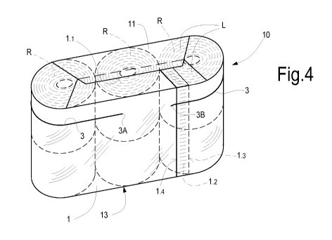
In the configuration of Fig. 1 or in that of Fig. 2, the plastic film 1 may be
used to form a pack of tissue paper rolls, as shown in Fig. 4. In this figure,
the plastic
film 1 of Fig. 2 is used, wherein the line-shaped element 3 has a length
smaller than
the longitudinal dimension of the plastic film 1.
In this embodiment, the pack, labeled 10 as a whole, contains an arrangement
of six tissue paper rolls R arranged on three rows, each of which comprises
two rolls.
It will be clearly apparent to those skilled in the art that the number and
arrangement
of the rolls may vary also significantly with respect to what illustrated in
Fig. 4 just
by way of non-limiting example. The pack 10 may comprise, for instance, two or
three overlying layers of rolls, each of which is formed by a matrix
arrangement, for
example 2x3=6 rolls.
The plastic film 1 is wrapped around the ordered group of rolls R so as to
wrap the side surface of the pack, surrounding the rolls cylindrical surfaces.
The
cross dimension of the plastic film 1 is such that it projects at two sides
with respect
to the flat surfaces of the rolls R. The two portions of plastic film 1
projecting with
CA 03036418 2019-03-11
WO 2018/046476 -5- PCT/EP2017/072190
respect to the bases of the rolls R form edges L, which are folded and sealed
onto the
two approximately flat opposite surfaces 11, 13 of the pack.
The transverse edges 1.3, 1.4 of the plastic film 1 are arranged on the side
surface of the pack and extend from one approximately flat surface of the pack
to the
other. In the illustrated example, the transverse edge 1.4 of the plastic film
1 is
outside the pack, whilst the transverse edge 1.3 is inside the pack. A welding
line
closing the pack 10 is provided between the two transverse edges 1.4 and 1.3.
The
welding line, schematically indicated with 12, preferably extends parallel to
the
transverse edges 1.4 and 1.3 and is spaced from the outer transverse edge 1.4
for
example by a distance comprised between 5 mm and 30 mm. The outer transverse
edge 1.4 can be therefore easily gripped by the user to open the pack as
described
below.
The folded edges of the plastic film 1 are welded in order to close the pack
in
the area of the longitudinal edges 1.1 e 1.2. The pack can also be closed by
means of
gluing.
The end 3A of the line-shaped element 3 is arranged inside the pack 10, while
the end 3B is arranged on the transverse edge 1.4 of the plastic film 1 and
can be
accessed from the outside.
In order to easily open the pack 10, the user can grip the end 3B of the line-
shaped element 3 and pull it, moving it away from the pack 10. As the welding
line
12 has been made at a certain distance from the transverse edge 1.4, the end
3B of
the line-shaped element 3 can be gripped more easily by the user.
By pulling the line-shaped element 3 towards the outside, the plastic film 1
tears along the line-shaped element 3.
Fig. 6 shows the pack 10 in open arrangement, after the plastic film 1 has
been torn through the action of the line-shaped element 3. Thanks to the fact
that the
end 3A of the line-shaped element 3 is provided in intermediate position with
respect
to the longitudinal extension of the plastic film 1, at a distance D from the
transverse
edge 1.3 (Fig. 2), not the whole plastic film 1 is broken along the line
defined by the
line-shaped element 3; namely a portion thereof, indicated with number 15 in
Fig. 6,
remains undamaged. In this way, the upper part 17 of the pack formed by the
plastic
film 1, above the line-shaped element 3, may be lifted, thus freeing the upper
layer of
rolls R. However, thanks to the undamaged portion 15 of plastic film 1, the
upper
part 17 of the pack 10 remains fastened to the remaining part, indicated with
19, of
CA 03036418 2019-03-11
WO 2018/046476 -6- PCT/EP2017/072190
the plastic film 1 wrapped around the pack 10. The rolls arranged below the
line-
shaped element 3 remain wrapped in the part 19 of the pack 10.
In this way it is possible, for example, to remove one roll R and to close, at
least partially, the pack using the portion 17 of the plastic film 1 like a
cover hinged
to the lower part 19 of the pack 10 at the portion 15
In order to prevent the plastic film 1 from being torn beyond the end 3A of
the line-shaped element 3, a device or member can be applied to the plastic
film 1 to
avoid tearing thereof, for example an adhesive label, that can also serve as
advertisement, decoration or mark for the packed product.
Also in the case the line-shaped element 3 has a longitudinal extension equal
to the longitudinal dimension of the edges 1.1 and 1.2, as shown in Fig. 1, it
is
possible to have a similar effect by using a member for avoiding the breakage
or
tearing of the plastic film 1. This member may be for example a self-adhesive
label,
indicated with 21 in Fig. 5. Pulling the line-shaped element 3 starting from
the end
3B accessible from the outside of the pack 10 along the transverse edge 1.3
results in
the film 1 being torn up to the area where the label 21 is provided. The label
21
avoids any subsequent tearing.
Having described the general features of the pack, now preferred features of
some embodiments will be described below.
In various embodiments of the pack, the line-shaped element may be
provided with an adhesive characterized by an adhesion to steel equal to, or
lower
than, 400 g/25 mm measured according to the FINAT FTM1 standard.
In some embodiments, the line-shaped element is arranged along a plane
orthogonal to the axes of the rolls R of the pack, the plane being spaced from
one of
the approximately flat opposite surfaces by a distance equal to, or lower than
40%,
and preferably equal to, or lower than 30%, and more preferably equal to, or
lower
than 25% of the overall distance between the two approximately flat opposite
surfaces.
In possible embodiments, the plastic film 1 may have a thickness comprised
between 15 and 50 micrometers, preferably between 20 and 40 micrometers. In
order
to enhance the features of the pack, the plastic film 1 may have an
anisotropic tensile
strength at break with different values in the direction parallel to the line-
shaped
element 3 and in the direction orthogonal to the line-shaped element 3.
The plastic film 1 may have a tensile strength at break in the direction
parallel
CA 03036418 2019-03-11
WO 2018/046476 -7- PCT/EP2017/072190
to the line-shaped element 3 lower than the tensile strength at break in the
direction
orthogonal to the line-shaped element 3. In some embodiments, the plastic film
1
may have an elongation at break in the direction parallel to the line-shaped
element 3
greater than the elongation at break in the direction orthogonal to the line-
shaped
element 3.
For example, the plastic film 1 may have a first tensile strength at break in
the
direction parallel to the line-shaped element 3 and a second tensile strength
at break
in the direction orthogonal to the line-shaped element 3. The ratio between
the first
tensile strength at break and the second tensile strength at break can be
comprised
between 1:1 and 1:2.5, and preferably between 1:1.05 and 1:2.3, the break
strength
being measured according to the ASTM D 882 standard.
Moreover, in possible embodiments, the plastic film 1 may have a first
elongation at break in the direction orthogonal to the line-shaped element 3
and a
second elongation at break in the direction parallel to the line-shaped
element 3. The
ratio between the first elongation at break and the second elongation at break
may be
comprised between 1:2 and 1:5.
The line-shaped element 3 may have a longitudinal elongation at break equal
to, or lower than, 50%, preferably equal to, or lower than, 40%, and more
preferably
equal to, or lower than, 30%. The longitudinal tensile strength at break of
the line-
shaped element 3 is preferably greater than the longitudinal tensile strength
at break
of the plastic film 1. For instance, the longitudinal tensile strength at
break of the
line-shaped element 3 can be preferably at least three times the longitudinal
tensile
strength at break of the plastic film 1.
In advantageous exemplary embodiments, the tensile strength at break of the
line-shaped element 3 is equal to, or greater than, 20 kg/25 mm according to
the
AFERA 4004 standard.