Note: Descriptions are shown in the official language in which they were submitted.
CA 03036464 2019-03-11
- 1 -
=
CLAD WELDED PIPE OR TUBE AND METHOD OF PRODUCING SAME
TECHNICAL FIELD
[0001] The present disclosure relates to a clad welded pipe or tube and a
method of producing the same.
BACKGROUND
[0002] There are various methods of producing a welded pipe or tube using a
steel sheet as raw material, such as a method by electric resistance welding
and a method by arc welding. However, it is commonly known that, with all
of these methods, the mechanical properties (toughness and strength) of the
weld degrade from the steel sheet before welding. Accordingly, in the
welded pipe or tube, the width (pipe or tube circumferential length) of
especially the weld metal in the weld needs to be reduced as much as possible.
An arc-welded steel pipe or tube such as a UOE steel pipe or tube is produced
by a welding method using welding material, and therefore is not suitable for
reduction of the width of the weld. On the other hand, electric resistance
welding is a self-welding method with no need for welding material, and thus
is advantageous in that the width of the weld in a welded pipe or tube
produced by this method can be reduced easily.
[0003] A technique proposed to improve the properties of an
electric-resistance-welded steel pipe or tube is an electric-resistance-welded
clad steel pipe or tube. The electric-resistance-welded clad steel pipe or
tube
is an electric-resistance-welded steel pipe or tube produced using a clad
steel
sheet that is obtained by cladding a steel sheet as base metal with a metal
sheet (cladding metal) made of a material different from the base metal.
Combining the different materials in this way makes it possible to obtain a
steel pipe or tube having excellent properties by benefiting from the
properties of both the base metal and the cladding metal. For example, in the
case of using carbon steel as the base metal and a stainless steel sheet as
the
cladding metal, an electric-resistance-welded clad steel pipe or tube having
both the corrosion resistance of the stainless steel sheet and the strength of
the
carbon steel can be obtained.
[0004] Techniques for such electric-resistance-welded clad steel pipes or
P0176721-PCT-ZZ (1/71)
CA 03036464 2019-03-11
- 2
tubes are disclosed in, for example, JP S60-221173 A (PTL 1) and JP
S62-156087 A (PTL 2).
[0005] PTL 1 discloses a method of producing a clad pipe or tube, whereby at
least the cladding metal-side bead of the weld bead formed by butt welding
both facing edges of a clad steel sheet or steel strip bent in a pipe or tube
shape is removed by cutting to a depth reaching the base metal, and the cut
portion is subjected to weld overlaying in which welding material having
similar properties to the cladding metal is used.
[0006] PTL 2 discloses a method of producing a clad steel pipe or tube,
whereby, after forming a clad steel strip into an open pipe or tube and
electric
resistance welding the joint edge parts, dissimilar metal that has entered the
welded seam is diluted. The dilution is performed by any of the following
methods (1) and (2): (1) A region to a depth of the clad interface along the
welded seam in which dissimilar metal has entered is melted and solidified to
dilute the dissimilar metal. (2) The seam part in which dissimilar metal has
entered is weld-overlaid using the same type of metal as the cladding metal,
and then the overlaid weld is rolled to dilute the dissimilar metal.
[0007] JP H5-154545 A (PTL 3) discloses a method of producing a clad steel
pipe or tube by electric resistance welding a clad steel sheet having cladding
metal on the inner surface side. The production method comprises forming
the clad steel sheet into a pipe-or-tube-shaped body so that the cladding
metal
forms the inner surface, subjecting at least a portion of butted parts of the
cladding metal of the pipe-or-tube-shaped body to electric resistance welding,
and then subjecting the non-welded butted parts to weld overlaying
CITATION LIST
Patent Literatures
[0008] PTL 1: JP S60-221173 A
PTL 2: JP S62-156087 A
PTL 3: JP H5-154545 A
SUMMARY
(Technical Problem)
[0009] The techniques described in PTL 1 to PTL 3 all need to perform, after
P0176721-PCT-ZZ (2/71)
CA 03036464 2019:03-11
- 3 -
the electric resistance welding, post-treatment such as weld overlaying or
melting and solidification on the weld, for the following reasons.
[0010] In the electric resistance welding, oxide-based weld defects called
penetrators occur in the weld, that is, the portion at which both
circumferential ends of the steel sheet formed into a pipe or tube shape are
butted. The penetrators decrease the toughness and strength of the weld.
To prevent the penetrators from remaining in the weld, a measure is typically
employed to increase the amount of upset by squeeze rolls so that oxidized
melts formed during the welding are discharged to outside the pipe or tube.
[0011] However, if the amount of upset is increased as described above in the
case of producing an electric-resistance-welded clad steel pipe or tube using
a
clad steel sheet as raw material, the following problem arises. FIG. 15A is a
diagram schematically illustrating a weld section when a clad steel sheet
composed of a base metal 11 and a cladding metal 12 is electric resistance
welded so that the cladding metal 12 is an inner layer. If the amount of upset
is large, the molten base metal 11 enters a welded seam part 14 of the
cladding
metal 12. In particular, if the amount of upset is excessively large, the base
metal 11 is exposed at the cladding metal 12-side surface of the steel pipe or
tube, as illustrated in FIG. 15A. This causes a decrease in performance in the
site where the base metal 11 is exposed, and impairs the advantage as a clad
steel pipe or tube.
[0012] For example, in the case of using a clad steel sheet obtained by
cladding low-carbon steel as the base metal 11 with stainless steel as the
cladding metal 12 for the purpose of corrosion resistance improvement, as a
result of the base metal 11 being exposed to the cladding metal side as
illustrated in FIG. 15A, i.e. as a result of the low-carbon steel inferior in
corrosion resistance being exposed to the cladding metal side, the corrosion
resistance near the welded seam part 14 at the steel pipe or tube inner
surface
decreases significantly.
[0013] To solve this problem, PTL 1 and PTL 2 propose subjecting the weld
to weld overlaying with the same material as the cladding metal after the
electric resistance welding. With this method, however, the weld with
inferior properties increases as a result of weld overlaying, although the
base
metal exposed part can be eliminated. PTL 2 also proposes a method
P0176721-PCT-ZZ (3/71)
CA 03036464 2019103-11
- 4 -
involving melting and solidification instead of weld overlaying. With this
method, however, the portion that has undergone melting and solidification
has solidification microstructure similar to the weld metal, and thus is
inferior
in properties.
[0014] With the method described in PTL 3, only the cladding metal side is
subjected to welding and then the base metal side is subjected to weld
overlaying, so that the base metal can be prevented from being exposed to the
cladding metal side. However, since the base metal is joined by weld
overlaying, the width of the weld metal increases as compared with the case of
joining the base metal by typical electric resistance welding.
100151 Thus, the conventional methods described in PTL 1 to PTL 3 cannot
simultaneously achieve the following two purposes: (1) reducing the width of
the weld metal in order to suppress property degradation caused by the weld
metal; and (2) preventing a decrease in performance as a clad welded pipe or
tube caused by the base metal being exposed to the cladding metal side. The
same problem occurs in the case of using, as raw material, a three-layer clad
steel sheet having cladding metal on the front and back of base metal. As
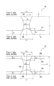
illustrated in FIG. 15B, if the amount of upset is large, molten base metal 11
enters a welded seam part 14 of cladding metal 12A or 12B, and the base
metal 11 is exposed at the cladding metal 12-side surface of the steel pipe or
tube (i.e. the inner surface and the outer surface of the steel pipe or tube).
[0016] It could therefore be helpful to provide a clad welded pipe or tube
that
has improved pipe or tube mechanical properties by reducing the width of
weld metal without its function as a clad pipe or tube being impaired, and a
method of producing the same.
(Solution to Problem)
[0017] We conducted intensive study to solve the problem stated above, and
discovered the following.
[0018] (A) Both transverse ends of a clad steel strip are butted parts (i.e.
parts
to be welded) in an open pipe or tube formed in a pipe or tube shape. By
indenting the transverse ends of the clad steel strip from the cladding metal
side to form a groove of a predetermined groove shape before electric
resistance welding, the molten base metal can be prevented from entering the
welded seam part of the cladding metal after the electric resistance welding.
P0176721-PCT-ZZ (4/71)
CA 03036464 2019r-03-11
- 5 -
[00191 (B) By blowing shielding gas under appropriate conditions using a
shielding-gas blowing nozzle having a specific structure during welding, the
oxygen concentration around the parts to be welded can be greatly reduced to
thus suppress penetrator formation.
[0020] (C) As a result of (B), even when the amount of upset is reduced,
penetrators will not remain in the weld, and the mechanical properties of the
weld can be improved. Moreover, by reducing the amount of upset, the
molten base metal can be prevented from being exposed at the cladding
metal-side surface.
[0021] (D) By precisely controlling the combination of the conditions of the
groove machining, the shielding gas, and the amount of upset mentioned
above, the exposure of the base metal at the cladding metal-side surface can
be completely prevented. Consequently, a clad welded pipe or tube excellent
in performance such as corrosion resistance can be obtained without
performing post-treatment such as weld overlaying or melting and
solidification as in the conventional techniques. Moreover, since the width
of the weld metal can be reduced significantly, the strength of the clad
welded
pipe or tube and in particular the fracture property of the weld can be
improved.
[0022] We thus provide:
[1] A clad welded pipe or tube comprising:
a first layer made of base metal; and
a second layer placed on one surface of the first layer, and made of
first cladding metal that is a material different from the base metal,
wherein a pipe or tube circumferential length of weld metal in a weld
(welded portion) at each of an inner surface and an outer surface of the clad
welded pipe or tube is 0.0010 mm or more and 1.0 mm or less, and
the base metal is not exposed at a first cladding metal-side surface of
the clad welded pipe or tube in the weld.
[0023] [2] The clad welded pipe or tube according to [1], having a two-layer
structure composed of the first layer and the second layer.
[0024] [3] The clad welded pipe or tube according to [2], wherein a pipe or
tube circumferential length of the weld metal at a thickness center of the
clad
welded pipe or tube is 0.0010 mm or more and 0.3 mm or less.
P0176721-PCT-ZZ (5171)
CA 03036464 2019-03-11
- 6 -
[0025] [4] The clad welded pipe or tube according to [2] or [3], wherein a
thickness of the first cladding metal in the weld metal is 20 A or more and
300
% or less of a thickness of the first cladding metal in parts other than the
weld
metal.
[0026] [5] The clad welded pipe or tube according to [1], having a three-layer
structure composed of a middle layer that is the first layer, an inner layer
that
is the second layer, and an outer layer that is a third layer placed on the
other
surface of the first layer and made of second cladding metal that is a
material
different from the base metal,
wherein the base metal is not exposed at the inner surface and the
outer surface of the clad welded pipe or tube in the weld.
[0027] [6] The clad welded pipe or tube according to [5], wherein a pipe or
tube circumferential length of the weld metal at a thickness center of the
clad
welded pipe or tube is 0.0010 mm or more and 0.3 mm or less.
[0028] [7] The clad welded pipe or tube according to [5] or [6], wherein a
thickness of the first cladding metal and a thickness of the second cladding
metal in the weld metal are respectively 20 % or more and 300 % or less of a
thickness of the first cladding metal and a thickness of the second cladding
metal in parts other than the weld metal, and are each 35 % or less of a
thickness of the clad welded pipe or tube.
[0029] [8] The clad welded pipe or tube according to [1], having a two-layer
structure composed of the first layer and the second layer,
wherein the base metal is carbon steel or low-alloy steel, and the first
cladding metal is stainless steel or a nickel-containing alloy, and
a width of the weld metal in the weld is 1.0 pm or more and 1000 um
or less, over a whole thickness of the clad welded pipe or tube.
[0030] [9] The clad welded pipe or tube according to [8], wherein the first
cladding metal is stainless steel having a chemical composition containing
(consisting of), in mass%,
C: 0.15 % or less,
Si: 5.0 % or less,
Mn: 2.0 % or less,
P: 0.1 % or less,
S: 0.1 % or less,
P0176721-PCT-ZZ (6/71)
CA 03036464 2019-03-11
- 7
Ni: 1.0 % or less,
Cr: 11.0 % or more, and
N: 0.5 % or less,
with the balance being Fe and inevitable impurities.
[0031] [10] The clad welded pipe or tube according to [8], wherein the first
cladding metal is stainless steel or a nickel-containing alloy having a
chemical
composition containing (consisting of), in mass%,
C: 0.15% or less,
Si: 5.0 % or less,
Mn: 2.0 % or less,
P: 0.1 % or less,
S: 0.1 % or less,
Ni: 6.0 % or more,
Cr: 15.0 % or more, and
N: 0.5 % or less,
with the balance being Fe and inevitable impurities.
[0032] [11] The clad welded pipe or tube according to [9] or [10], wherein the
chemical composition of the first cladding metal further contains, in mass%,
one or more selected from the group consisting of
Mo: 20.0 % or less,
Cu: 5.0 % or less,
Al: 2.0 % or less,
Co: 3.0 % or less,
W: 5.0 % or less,
Ta: 5.0 % or less,
Ti: 2.0 % or less,
Nb: 5.0 % or less,
V: 2.0 % or less,
Zr: 2.0 % or less,
B: 0.0050 % or less,
Ca: 0.0050 % or less,
Mg: 0.0030 % or less, and
REM: 0.10 % or less.
[0033] [12] The clad welded pipe or tube according to any one of [8] to [11],
P0176721-PCT-ZZ (7/71)
CA 03036464 2019L03-11
=
- 8 -
wherein the base metal is carbon steel or low-alloy steel having a chemical
composition containing (consisting of), in mass%,
C: 0.02 % to 0.20 %,
Si: 0.01 % to 1.0 %,
Mn: 0.1 % to 2.0 %,
P: 0.05 % or less,
S: 0.01 % or less, and
Al: 0.1 % or less,
with the balance being Fe and inevitable impurities.
[0034] [13] The clad welded pipe or tube according to [12], wherein the
chemical composition of the base metal further contains, in mass%, one or
more selected from the group consisting of
Ti: 0.1 % or less,
Nb: 0.2 % or less,
Cu: 0.5 % or less,
Ni: 0.5 % or less,
Cr: 0.5 % or less,
Mo: 0.5 % or less,
V: 0.1 % or less, and
Ca: 0.0005 % to 0.0050 %.
[0035] [14] The clad welded pipe or tube according to any one of [1] to [13],
wherein a flatness value h/D in a 90 flattening test in accordance with JIS G
3445 is less than 0.3, where h is a flattening crack height in mm, and D is a
pipe or tube outer diameter in mm.
[0036] [15] A method of producing a clad welded pipe or tube, the method
comprising:
preparing a clad steel strip including a first layer made of base metal
and a second layer placed on one surface of the first layer and made of first
cladding metal that is a material different from the base metal;
subjecting both transverse ends of the clad steel strip to groove
machining, to form a groove (bevel);
forming the clad steel strip into a pipe or tube shape, to obtain an open
pipe or tube that is a cylindrical strip before welding; and
electric resistance welding a pair of butted parts of the open pipe or
P0176721-PCT-ZZ (8171)
CA 03036464 2019-03-11
- 9
tube facing each other, to obtain a clad welded pipe or tube,
wherein in the groove machining, the transverse ends of the clad steel
strip are indented from a second layer side,
the groove satisfies the following conditions:
a clad interface between the second layer and the first layer turns from
the second layer side toward a thickness center of the clad steel strip;
a bevel angle 01 on the second layer side is 10 or more and 50 or
less:
a groove depth dl is 10.0 % or more and 45.0 % or less of a thickness t
of the clad steel strip; and
a projection clad ratio R1 defined by the following Expression (1) is
25 % or more and 50 % or less,
R1 = (tci* + d1)/t x 100 (%) (1)
where R1 is the projection clad ratio, tel* is a thickness of the second
layer at a root surface in mm, dl is the groove depth on the second layer side
in mm, and t is the thickness of the clad steel strip in mm,
the electric resistance welding is performed by, while subjecting the
pair of butted parts to gas shielding, butt pressing the pair of butted parts
with
an amount of upset of not greater than the thickness t of the clad steel
strip,
and
the gas shielding is performed by blowing a shielding gas using a
shielding-gas blowing nozzle having three or more slit-shaped gas outlets
arranged in parallel with and adjacent to each other in a butting direction of
the open pipe or tube at a position of 5 mm to 300 mm above upper ends of the
butted parts of the open pipe or tube, under conditions that B is 0.5 m/s to
50
m/s and 0.010 B/A 10, where A is a gas release flow rate in m/s from a
pair of first gas outlets located at both ends among the gas outlets, and B is
a
gas release flow rate in m/s from a second gas outlet other than the first gas
outlets.
[0037] [16] The method of producing a clad welded pipe or tube according to
[15], wherein the clad welded pipe or tube has a two-layer structure composed
of the first layer and the second layer, and
the groove is a Y-groove.
[0038] [17] The method of producing a clad welded pipe or tube according to
P01 76721-PCT-ZZ (9/71)
CA 03036464 2019-03-11
1 0 -
t
[16], wherein the amount of upset is 20 % or more of a thickness tc1 of the
first cladding metal of the clad steel strip.
100391 [18] The method of producing a clad welded pipe or tube according to
[16] or [17], wherein the projection clad ratio R1 is 30 % or more and 50 % or
less.
[0040] [19] The method of producing a clad welded pipe or tube according to
[15], wherein the clad welded pipe or tube has a three-layer structure
composed of a middle layer that is the first layer, an inner layer that is the
second layer, and an outer layer that is a third layer placed on the other
surface of the first layer and made of second cladding metal that is a
material
different from the base metal,
in the groove machining, further the transverse ends of the clad steel
strip are indented from a third layer side,
the groove is an X-groove,
the groove further satisfies the following conditions:
a clad interface between the third layer and the first layer turns from
the third layer side toward the thickness center of the clad steel strip;
a bevel angle 02 on the third layer side is 100 or more and 50 or less;
a groove depth d2 is 10.0 % or more and 45.0 % or less of the
thickness t of the clad steel strip; and
a projection clad ratio R2 defined by the following Expression (2) is
% or more and 50 % or less,
R2 = (t,2* + d2)/t x 100 (%) ... (2)
where R2 is the projection clad ratio, tc2* is a thickness of the third
25 layer at the root surface in mm, d2 is the groove depth on the third
layer side
in mm, and t is the thickness of the clad steel strip in mm.
[0041] [20] The method of producing a clad welded pipe or tube according to
[19], wherein each of the projection clad ratio R1 and the projection clad
ratio
R2 is 30 % or more and 50 % or less.
(Advantageous Effect)
[0042] With the method of producing a clad welded pipe or tube according to
the present disclosure, it is possible to produce a clad welded pipe or tube
that
has improved pipe or tube mechanical properties by reducing the width of a
weld without its function as a clad pipe or tube being impaired.
P0176721-PCT-ZZ (10/71)
85133306
-11-
100431 The clad welded pipe or tube according to the present disclosure has
improved pipe
or tube mechanical properties by reducing the width of a weld without its
function as a clad
pipe or tube being impaired.
[0043a] According to one aspect of the present invention, there is provided a
clad welded
pipe or tube, having a two-layer structure composed of a first layer made of
base metal and a
second layer placed on one surface of the first layer and made of first
cladding metal that is a
material different from the base metal, wherein a weld metal in a weld is
composed of the
base metal and the first cladding metal, wherein a pipe or tube
circumferential length of the
weld metal in the weld at each of an inner surface and an outer surface of the
clad welded pipe
or tube is 0.0010 mm or more and 1.0 mm or less, and wherein the base metal is
not exposed
at a first cladding metal-side surface of the clad welded pipe or tube in the
weld.
10043b1 According to another aspect of the present invention, there is
provided a clad welded
pipe or tube, having a three-layer structure composed of a middle layer that
is a first layer
made of base metal, an inner layer that is a second layer, placed on one
surface of the first
layer and made of first cladding metal that is a material different from the
base metal, and an
outer layer that is a third layer placed on the other surface of the first
layer and made of
second cladding metal that is a material different from the base metal,
wherein a weld metal in
a weld is composed of the base metal, the first cladding metal, and the second
cladding metal,
wherein a pipe or tube circumferential length of the weld metal in the weld at
each of an inner
surface and an outer surface of the clad welded pipe or tube is 0.0010 mm or
more and 1.0mm
or less, and wherein the base metal is not exposed at the inner surface and
the outer surface of
the clad welded pipe or tube in the weld.
[0043c] According to still another aspect of the present invention, there is
provided a clad
welded pipe or tube having a two-layer structure composed of a first layer
made of base metal
and a second layer placed on one surface of the first layer and made of first
cladding metal
that is a material different from the base metal, wherein a weld metal in a
weld is composed of
the base metal and the first cladding metal, wherein a pipe or tube
circumferential length of
the weld metal in the weld at each of an inner surface and an outer surface of
the clad welded
pipe or tube is 0.0010mm or more and 1.0 mm or less, wherein the base metal is
not exposed
at a first cladding metal-side surface of the clad welded pipe or tube
Date Recue/Date Received 2020-06-29
85133306
- ha-
in the weld, wherein the base metal is carbon steel or low-alloy steel, and
the first cladding
metal is stainless steel or a nickel-containing alloy, and wherein a width of
the weld metal in
the weld is 1.0 pn or more and 1000 gm or less, over a wall thickness of the
clad welded pipe
or tube.
[0043d] According to yet another aspect of the present invention, there is
provided a method
of producing a clad welded pipe or tube, the method comprising: preparing a
clad steel strip
including a first layer made of base metal and a second layer placed on one
surface of the first
layer and made of first cladding metal that is a material different from the
base metal;
subjecting both transverse ends of the clad steel strip to groove machining,
to form a groove;
forming the clad steel strip into a pipe or tube shape, to obtain an open pipe
or tube that is a
cylindrical strip before welding; and electric resistance welding a pair of
butted parts of the
open pipe or tube facing each other, to obtain a clad welded pipe or tube,
wherein in the
groove machining, the transverse ends of the clad steel strip are indented
from a second layer
side, the groove satisfies the following conditions: a clad interface between
the second layer
and the first layer turns from the second layer side toward a thickness center
of the clad steel
strip; a bevel angle 01 on the second layer side is 100 or more and 50 or
less; a groove depth
dl is 10.0 % or more and 45.0 % or less of a thickness t of the clad steel
strip; and a projection
clad ratio R1 defined by the following Expression (1) is 25 % or more and 50 %
or less, R1 =
(Li* + d1)/t x 100 (%) ...(1) where R1 is the projection clad ratio, Li* is a
thickness of the
second layer at a root surface in mm, dl is the groove depth on the second
layer side in mm,
and t is the thickness of the clad steel strip in mm, the electric resistance
welding is performed
by, while subjecting the pair of butted parts to gas shielding, butt pressing
the pair of butted
parts with an amount of upset of not greater than the thickness t of the clad
steel strip, and the
gas shielding is performed by blowing a shielding gas using a shielding-gas
blowing nozzle
having three or more slit-shaped gas outlets arranged in parallel with and
adjacent to each
other in a butting direction of the open pipe or tube at a position of 5 mm to
300 mm above
upper ends of the butted parts of the open pipe or tube, under conditions that
B is 0.5 m/s to
50 m/s and 0.010 < B/A < 10, where A is a gas release flow rate in m/s from a
pair of first gas
outlets located at both ends among the gas outlets, and B is a gas release
flow rate in m/s from
a second gas outlet other than the first gas outlets.
Date Recue/Date Received 2020-06-29
85133306
- 1 lb -
BRIEF DESCRIPTION OF THE DRAWINGS
[0044] In the accompanying drawings:
FIG. 1 is a sectional diagram of the vicinity of a weld of a clad welded pipe
or tube
20 according to Embodiment 1 of the present disclosure perpendicular to the
pipe or tube
longitudinal direction;
FIG. 2 is a schematic diagram of a production line for a clad welded pipe or
tube
according to Embodiments 1 to 3 of the present disclosure;
FIG. 3A is a sectional diagram illustrating a groove shape of both transverse
ends
(butted parts) of a clad steel strip in Embodiment 1 of the present
disclosure;
FIG. 3B is a sectional diagram illustrating the weld and its vicinity after
electric
resistance welding the clad steel strip;
FIG. 4 is a schematic diagram illustrating a groove machine (beveling machine)
usable in Embodiment 1 of the present disclosure;
FIG. 5A is a schematic diagram for explaining gas shielding in Embodiment 1 of
the
present disclosure, and is a perspective diagram of an open pipe or tube 16
and the clad
welded pipe or tube 20 which are being transferred;
FIG. 5B is a schematic diagram for explaining gas shielding, and is an
enlarged
perspective diagram of a shielding-gas blowing nozzle 81 in a Z1 portion in
FIG. 5A;
FIG. 5C is a schematic diagram for explaining gas shielding, and is a
sectional
diagram of a Z2 portion in FIG. 5A;
FIG. 6A is a schematic diagram illustrating an example of a nozzle usable in
Embodiments 1 to 3 of the present disclosure;
FIG. 6B is a schematic diagram illustrating an example of the nozzle usable in
Embodiments 1 to 3 of the present disclosure;
FIG. 6C is a schematic diagram illustrating an example of the nozzle usable in
Embodiments 1 to 3 of the present disclosure;
FIG. 6D is a schematic diagram illustrating an example of the nozzle
Date Recue/Date Received 2020-06-29
CA 03036464 2019-03-11
- 12 -
usable in Embodiments 1 to 3 of the present disclosure;
FIG. 7A is a diagram for explaining an appropriate range of a gas
release flow rate B and a gas flow rate ratio B/A of shielding gas in
Embodiment 1 of the present disclosure;
FIG. 7B is a diagram for explaining the appropriate range of the gas
release flow rate B and the gas flow rate ratio B/A of the shielding gas in
Embodiment 1 of the present disclosure;
FIG. 7C is a diagram for explaining the appropriate range of the gas
release flow rate B and the gas flow rate ratio B/A of the shielding gas in
Embodiment 1 of the present disclosure;
FIG. 8 is a graph illustrating the relationship between the gas flow rate
ratio B/A of the shielding gas and the oxygen concentration around the parts
to be welded;
FIG. 9 is a graph illustrating the relationship between the oxygen
concentration around the parts to be welded and the flatness value h/D of the
electric-resistance-welded stainless clad steel pipe or tube in a 90
flattening
test;
FIG. 10 is a sectional diagram of the vicinity of a weld of a clad
welded pipe or tube 20 according to Embodiment 2 of the present disclosure
perpendicular to the pipe or tube longitudinal direction;
FIG. 11A is a sectional diagram illustrating a groove shape of both
transverse ends (butted parts) of a clad steel strip in Embodiment 2 of the
present disclosure;
FIG. 11B is a sectional diagram illustrating the weld and its vicinity
after electric resistance welding the clad steel strip;
FIG. 12 is a schematic diagram illustrating a groove machine usable in
Embodiment 2 of the present disclosure;
FIG. 13A is a schematic diagram for explaining gas shielding in
Embodiment 2 of the present disclosure, and is a perspective diagram of an
open pipe or tube 16 and the clad welded pipe or tube 20 which are being
transferred;
FIG. 13B is a schematic diagram for explaining gas shielding, and is
an enlarged perspective diagram of a shielding-gas blowing nozzle 81 in a Z1
portion in FIG. 13A;
PO 1 76721-PCT-ZZ (12/71)
CA 03036464 2019-03-11
- 13
FIG. 13C is a schematic diagram for explaining gas shielding, and is a
sectional diagram of a Z2 portion in FIG. 13A;
FIG. 14A is a diagram for explaining an appropriate range of a gas
release flow rate B and a gas flow rate ratio B/A of shielding gas in
Embodiment 2 of the present disclosure;
FIG. 14B is a diagram for explaining the appropriate range of the gas
release flow rate B and the gas flow rate ratio B/A of the shielding gas in
Embodiment 2 of the present disclosure;
FIG. 14C is a diagram for explaining the appropriate range of the gas
release flow rate B and the gas flow rate ratio B/A of the shielding gas in
Embodiment 2 of the present disclosure;
FIG. 15A is a schematic sectional diagram of an electric resistance
weld and its vicinity in the case where a two-layer clad steel sheet is used
as
raw material and the amount of upset is large;
FIG. 15B is a schematic sectional diagram of an electric resistance
weld and its vicinity in the case where a three-layer clad steel sheet is used
as
raw material and the amount of upset is large; and
FIG. 15C is a schematic sectional diagram of an electric resistance
weld and its vicinity in the case where a two-layer clad steel sheet is used
as
raw material and the amount of upset is small.
DETAILED DESCRIPTION
[0045] A clad welded pipe or tube according to the present disclosure
includes at least a first layer made of base metal and a second layer placed
on
.. one surface of the first layer and made of first cladding metal that is a
material
different from the base metal. A clad welded pipe or tube according to one
of the disclosed embodiments may be a clad welded pipe or tube having a
two-layer structure composed of the first layer and the second layer. A clad
welded pipe or tube according to another one of the disclosed embodiments
may further include a third layer placed on the other surface of the first
layer.
In other words, the clad welded pipe or tube may be a clad welded pipe or tube
having a three-layer structure composed of the first layer (middle layer), the
second layer (inner layer) placed on one surface of the first layer, and the
third layer (outer layer) placed on the other surface of the first layer.
P0176721-PCT-ZZ (13/71)
CA 03036464 2019-03-11
- 14 -
[0046] Herein, "base metal" denotes the material of the thickest layer in a
clad steel strip made up of two or more layers that differ in thickness, and
"cladding metal" denotes the material of the other layer(s). For example, for
a clad steel strip used to produce a clad welded pipe or tube, a material for
ensuring the strength of the pipe or tube may be selected as the base metal,
and a material for ensuring properties (e.g. corrosion resistance) not
obtainable with the base metal may be selected as the cladding metal.
[0047] A method for carrying out the presently disclosed techniques will be
described in detail below, using an example in which a clad welded pipe or
tube has a two-layer structure (Embodiments I and 3) and an example in
which a clad welded pipe or tube has a three-layer structure (Embodiment 2).
[0048] (Embodiment 1)
An example in which a clad welded pipe or tube has a two-layer
structure will be described first.
[0049] [Clad welded pipe or tube]
A clad welded pipe or tube 20 according to Embodiment 1 of the
present disclosure will be described below, with reference to FIG. 1. The
clad welded pipe or tube 20 according to this embodiment is a two-layer clad
welded pipe or tube composed of a first layer 11 made of base metal and a
second layer 12 made of first cladding metal that is a material different from
the base metal.
[0050] (Base metal)
The base metal is not limited, and may be a metal containing a steel
material such as carbon steel or low-alloy steel.
[0051] The carbon steel used as the base metal is not limited. It is, however,
preferable to select a carbon steel whose specifications and mechanical
properties are appropriate to the application of the clad welded pipe or tube,
because the mechanical properties of the clad welded pipe or tube depend on
the properties of the base metal occupying the major portion of the pipe or
tube volume.
[0052] The low-alloy steel used as the base metal is not limited, as long as
its
total content of alloying elements is 5 mass% or less. A low-alloy steel may
be selected according to the application of the clad welded pipe or tube, as
with the carbon steel.
P0176721-PCT-ZZ (14/71)
CA 03036464 2019-03-11
- 15
[0053] (First cladding metal)
The first cladding metal is not limited, and may be a corrosion
resistant alloy of a metal containing a steel material such as stainless steel
or a
nickel-containing alloy. The stainless steel is preferably SUS316L, and the
nickel-containing alloy is preferably Alloy625 or A1loy825, in terms of having
particularly high corrosion resistance.
[0054] Which of the first layer 11 made of the base metal and the second
layer 12 made of the first cladding metal forms the inner layer of the pipe or
tube and which of the first layer 11 and the second layer 12 forms the outer
layer of the pipe or tube are not limited, and may be determined depending on
the use of the clad welded pipe or tube. For example, in a line pipe used in a
high corrosive environment, the pipe or tube inner surface where a product
fluid flows is required to have high corrosion resistance. Accordingly, in the
case of using the clad welded pipe or tube for a line pipe, the first cladding
metal may be used as the inner layer and the base metal as the outer layer. In
applications where the pipe or tube outer surface is required to have high
corrosion resistance, on the other hand, the base metal may be used as the
inner layer and the first cladding metal as the outer layer.
[0055] (Width of weld metal and exposure of base metal)
With reference to FIG. 1, in the clad welded pipe or tube 20 according
to this embodiment, the width (pipe or tube circumferential length) Li at the
pipe or tube inner surface and the width (pipe or tube circumferential length)
L2 at the pipe or tube outer surface of weld metals 15B and 15A in the weld
are each 0.0010 mm or more and 1.0 mm or less, and the base metal is not
exposed at the first cladding metal-side surface of the clad welded pipe or
tube in the weld. As a result of the weld metal being present from the inner
surface through to the outer surface of the pipe or tube and also having a
narrow width (Li and L2) of 1.0 mm or less, the clad welded pipe or tube 20
has excellent mechanical properties. Moreover, since the base metal is not
exposed at the cladding metal-side surface of the clad welded pipe or tube in
the weld, the function as a clad pipe or tube is not impaired.
[0056] If Ll is less than 0.0010 mm, the amount of weld metal on the pipe or
tube inner surface side is excessively small, and the strength of the weld
decreases. Likewise, if L2 is less than 0.0010 mm, the amount of weld metal
P0176721-PCT-ZZ (15/71)
CA 03036464 2019-03-11
- 16 -
on the pipe or tube outer surface side is excessively small, and the strength
of
the weld decreases. If at least one of Ll and L2 is more than 1.0 mm, the
range of weld metal increases, so that the mechanical properties of the pipe
or
tube degrade. In view of this, Li and L2 are preferably 0.0100 mm to 0.5
mm.
[00571 The width (pipe or tube circumferential length) L3 of weld metal at
the pipe or tube thickness center is preferably 0.0010 mm or more and 0.3 mm
or less. If L3 is 0.0010 mm or more, a decrease in the strength of the weld
caused by the amount of weld metal being excessively small is prevented. If
L3 is 0.3 mm or less, degradation in the mechanical properties of the pipe or
tube caused by an increase in the range of weld metal is prevented. In view
of this, L3 is more preferably 0.0100 mm to 0.3 mm.
100581 The thickness tw1 of the first cladding metal in the weld metal (the
thickness of the second layer in the welded seam part) is preferably 20 % or
more and 300 c1/0 or less of the thickness tc1 of the first cladding metal in
the
parts other than the weld metal. If tw1 is 20% or more of tel, the entry of
the
weld metal 15A of the base metal into the weld metal 15B of the first cladding
metal can be suppressed sufficiently, and sufficient properties (e.g.
corrosion
resistance) of the first cladding metal can be obtained at the first cladding
metal-side surface of the pipe or tube. If twi is 300 % or less of ti, the
weld
metal 15B of the first cladding metal is not dominant in the weld, and
sufficient properties (e.g. strength) of the base metal can be obtained. In
view of this, ti is more preferably 50% to 200 % of tc1.
[0059] Herein, "weld metal" denotes metal that has melted during welding
and subsequently solidified, in a welded pipe or tube. A welded pipe or tube
is composed of a weld made up of weld metal and a heat-affected zone
surrounding the weld metal, and a non-weld not heat-affected by welding.
[0060] In the present disclosure, the weld metal is identified by the
following
method. A region that reliably includes a weld in a section of the welded
pipe or tube perpendicular to the pipe or tube longitudinal direction is
etched
by an appropriate method, and a region exhibiting morphology different from
a non-weld is identified as the weld metal. Here, an appropriate etching
solution may be selected depending on the type of the metal. For example,
for weld metal of carbon steel or low-alloy steel, the section is etched with
P0176721-PCT-ZZ (16/71)
CA 03036464 2019-03-11
- 17 -
natal, and a region observed as white by an optical microscope is identified
as
the weld metal. For weld metal of stainless steel or a Ni-containing alloy,
the section is etched with aqua regia, and a region observed as black by an
optical microscope and containing solidification microstructure in, for
example, dendritic or cellular form is identified as the weld metal. The weld
metal 15A of the base metal and the weld metal 15B of the cladding metal in
FIG. 1 can thus be identified. Both circumferential edges of the weld metal
at each of the outer surface and the inner surface in the identified region of
the
weld metal in the section are connected by a straight line, and each of the
length of the straight line is taken to be the outer surface width and the
inner
surface width of the weld metal, respectively. Regarding the thickness
center width of the weld metal, too, both edges of the weld metal region at a
thickness center of the clad welded pipe or tube are connected by a straight
line, and the length of the straight line is taken to be the thickness center
width of the weld metal.
[0061] Alternatively, weld metal of carbon steel or low-alloy steel may be
identified as a region observed to have no segregation line when metal flow is
revealed by etching the section with picric acid. Likewise, weld metal of
stainless steel or a Ni-containing alloy may be identified as a region
observed
to have no segregation line when metal flow is revealed.
[0062] The weld in the clad welded pipe or tube 20 according to this
embodiment preferably has high fracture property. Specifically, the flatness
value h/D in a 90 flattening test in accordance with JIS G 3445 is preferably
less than 0.3, where h is the flattening crack height (mm) and D is the pipe
or
tube outer diameter (mm).
[0063] [Method of producing clad welded pipe or tube]
The above-described clad welded pipe or tube 20 according to
Embodiment 1 of the present disclosure can be produced by electric resistance
welding under specific conditions described below.
100641 A process of producing a clad welded pipe or tube according to
Embodiment 1 of the present disclosure is described below, with reference to
FIG. 2. The production of a clad welded pipe or tube according to
Embodiment I of the present disclosure includes the following steps: First, a
clad steel strip 10 in the form of a hot rolled coil is continuously uncoiled
by
P0176721-PCT-ZZ (17/71)
CA 03036464 2019-03-11
- 18 -
an uncoiler 30. After this, both transverse ends of the uncoiled clad steel
strip 10 are subjected to groove machining by a groove machine 40. The
clad steel strip 10 is then formed into a pipe or tube shape by a roll former
50.
Following this, the transverse ends as butted parts (parts to be welded) are,
while being heated to a melting point or more by a high-frequency heating
device 60, butt pressed by squeeze rolls 70 to be electric resistance welded,
thus obtaining a clad welded pipe or tube 20. During this, the butted parts
are subjected to gas shielding by a shielding-gas blowing device 80. After
this, the weld bead on the outer surface and inner surface of the weld is cut
by
a bead cutter 90. Subsequently, the pipe or tube 20 is cut to a predetermined
length by a cutter 96.
[0065] The high-frequency heating device 60 may be any of a direct current
heating device and an induction heating device. Electric resistance welding
may be performed with an impeder (not illustrated) inserted on the pipe or
tube inner surface side within a pipe or tube passage direction region
including a current passage portion of high-frequency current.
[0066] This embodiment describes an example in which electric resistance
welding is performed using the clad steel strip 10 obtained by
pressure-bonding the first layer 11 made of the base metal and the second
layer 12 made of the first cladding metal where the second layer 12 is the
inner layer and the first layer 11 is the outer layer, as illustrated in FIG.
3A.
[0067] (Groove machining)
In this embodiment, both transverse ends of the clad steel strip are
subjected to groove machining to form a groove. This groove machining will
be described below, with reference to FIG. 3A.
[0068] In the groove machining, both transverse ends of the clad steel strip
10
are indented from the second layer 12 side. The groove formed is a Y-groove
as illustrated in FIG. 3A, and satisfies the following conditions (i) to (iv):
(i) A clad interface 13 which is the interface between the second layer
12 and the first layer 11 turns from the second layer side toward the
thickness
center of the clad steel strip.
(ii) The bevel angle 01 on the second layer side is 100 or more and 50
or less.
(iii) The groove depth dl is 10.0 % or more and 45.0 % or less of the
P0176721-PCT-ZZ (18/71)
CA 03036464 2019-03-11
- 19 -
thickness t of the clad steel strip.
(iv) The projection clad ratio R1 defined by the following Expression
(1) is 25 % or more and 50 % or less:
R1 = (tel* + d1)/t x 100 (%) (1)
where R1 is the projection clad ratio, tc1* is the thickness (mm) of the
second layer at the root surface, dl is the groove depth (mm) on the second
layer side, and t is the thickness (mm) of the clad steel strip.
[0069] It is important that the Y-groove is formed by indenting the transverse
ends of the clad steel strip 10 from the second layer 12 side, and not by
cutting off the second layer-side corners of the transverse ends of the clad
steel strip 10. As a result, the clad interface 13 is also indented from the
second layer side toward the thickness center of the clad steel strip. In
addition, the bevel angle 01, the groove depth dl, and the projection clad
ratio
R1 are set to the foregoing ranges. Thus, the entry of the molten steel and
the heat-affected zone of the base metal into the welded seam part of the
first
cladding metal after electric resistance welding can be suppressed.
Consequently, the base metal is kept from being exposed at the first cladding
metal-side surface of the steel pipe or tube (the inner surface in this
embodiment) in the weld. This makes it possible to obtain an
electric-resistance-welded clad steel pipe or tube whose inner surface is
entirely, including the weld, covered with the first cladding metal, after
cutting the inner surface bead of the weld.
10070] Moreover, since the groove shape has no corners at which current
concentrates, the temperature distribution of the whole parts to be welded is
uniform. This facilitates discharging of penetrators from the weld, and thus
prevents a decrease in the toughness and strength of the weld.
10071] If the bevel angle 01 is less than 10 , the uniformity of the
temperature distribution of the whole parts to be welded cannot be maintained,
as a result of which discharging of penetrators tends to be insufficient. This
causes insufficient properties such as toughness and strength of the weld.
Besides, the width Li or L2 of the molten metal exceeds 1.0 mm, so that the
mechanical properties of the pipe or tube degrade.
[0072] If the bevel angle 01 is more than 50 , the effect of suppressing the
entry of the molten steel and the heat-affected zone of the base metal into
the
P0176721-PCT-ZZ (19/71)
CA 03036464 2019-03-11
- 20 -
welded seam part of the first cladding metal is insufficient. Consequently,
the base metal is exposed at the first cladding metal-side surface of the
steel
pipe or tube in the weld, which impairs the function as a clad pipe or tube.
Besides, the width L 1 or L2 of the molten metal exceeds 1.0 mm, so that the
mechanical properties of the pipe or tube degrade.
[0073] If the groove depth dl is less than 10.0 % of the thickness t of the
clad
steel strip, the effect of suppressing the entry of the molten steel and the
heat-affected zone of the base metal into the welded seam part of the first
cladding metal is insufficient. Consequently, the base metal is more likely to
be exposed at the first cladding metal-side surface of the steel pipe or tube
in
the weld. Besides, the width Li or L2 of the molten metal exceeds 1.0 mm,
so that the mechanical properties of the pipe or tube degrade.
[0074] If the groove depth dl is more than 45.0 % of the thickness t of the
clad steel strip, the composition of the weld is a high-alloy composition
similar to the composition of the cladding metal. This causes insufficient
properties such as toughness and strength of the weld. Besides, the width LI
or L2 of the molten metal exceeds 1.0 mm, so that the mechanical properties
of the pipe or tube degrade.
[0075] In terms of achieving both the prevention of the exposure of the base
metal at the first cladding metal-side surface and the prevention of a
decrease
in the properties of the weld at higher level, the bevel angle 01 is
preferably
15 or more, the bevel angle 01 is preferably 35 or less, the groove depth dl
is preferably 15 % or more of the thickness t of the clad steel strip, and the
groove depth dl is preferably 35 % or less of the thickness t of the clad
steel
strip.
[0076] It is also very important in this embodiment that the projection clad
ratio RI defined by Expression (1) is 25 % or more and 50 % or less. If the
projection clad ratio R1 is less than 25 %, the effect of suppressing the
entry
of the molten steel and the heat-affected zone of the base metal into the
welded seam part of the first cladding metal is insufficient. Consequently,
the base metal is exposed at the first cladding metal-side surface of the
steel
pipe or tube in the weld. Moreover, with a low projection clad ratio of less
than 25 %, the groove shape is close to a rectangle. In such a case, due to
the
properties of high-frequency current, current tends to concentrate only at
P0176721-PCT-ZZ (20/71)
CA 03036464 2019-03-11
- 2 1
corners, facilitating heating. Besides, given that the metal of high-alloy
composition such as stainless steel or a Ni alloy as the first cladding metal
has
a lower melting point than the base metal such as low-carbon low-alloy steel,
with a low projection clad ratio of less than 25 %, the first cladding metal
of
low melting point at the corners melts easily. This causes the width of the
weld metal of the first cladding metal to be not uniform, as a result of which
Ll or L2 exceeds 1.0 mm.
[0077] If the projection clad ratio R1 is more than 50 %, that is, if the
position of the clad interface at the root surface of the Y-groove is on the
base
metal side of the wall thickness center of the clad steel strip 10, the most
part
of the welded seam 14 after electric resistance welding is a welded seam
resulting from electric resistance welding the metal of high-alloy composition
as the first cladding metal, so that the properties of the weld such as
toughness
and strength decrease. Besides, given that the metal of high-alloy
composition such as stainless steel or a Ni alloy as the first cladding metal
has
a lower melting point than the base metal such as low-carbon low-alloy steel,
with a high projection clad ratio of more than 50 %, the first cladding metal
of
low melting point melts excessively. As a result, the width L 1 or L2 of the
weld metal exceeds 1.0 mm.
[0078] In the case of using the electric-resistance-welded clad steel pipe or
tube as a line pipe for transporting a corrosive substance, to maintain the
corrosion resistance of the inner surface of the clad steel pipe or tube for
the
long term, the thickness tw1 of the first cladding metal in the weld metal is
preferably 20 % or more of the thickness tc1 of the first cladding metal in
the
parts other than the weld metal, as mentioned earlier. To achieve this, the
projection clad ratio R1 of the Y-groove of the butted parts in the electric
resistance welding is preferably set to 30 % or more.
[0079] The groove machining in this embodiment can be performed using, for
example, a groove machine 40 illustrated in FIG. 4. The groove machine 40
is a rolling-type groove machine capable of continuously machining the
running clad steel strip 10, and includes a pair of right and left upper side
rolls 42 and a pair of right and left lower side rolls 44. As a result of the
upper side rolls 42 having a rolling portion 42A that increases in diameter
upward in reverse taper shape as illustrated in FIG. 4, the Y-groove can be
P0176721-PCT-ZZ (21/71)
CA 03036464 2019-4/3-11
- 22
formed at both transverse ends of the clad steel strip 10.
[0080] By changing the reverse taper shape of the rolling portion 42A, the
groove shape of the transverse ends of the clad steel strip can be adjusted as
desired. As illustrated in FIG. 3A, the projection clad ratio R1 depends on
the ratio of the thickness tm of the first layer (base metal) and the
thickness Ici
of the second layer (first cladding metal) in the clad steel strip 10 and the
groove shape by the indentation. Accordingly, the projection clad ratio R I
can be set to a desired value by selecting the ratio appropriately and also
adjusting the reverse taper shape of the rolling portion 42A to form an
appropriate groove shape.
[0081] (Gas shielding)
Next, as illustrated in FIGS. 5A and 5C, the clad steel strip 10 is
formed into a pipe or tube shape, to obtain an open pipe or tube 16 that is a
cylindrical strip before welding. A pair of butted parts (parts to be welded)
17 of the open pipe or tube facing each other are, while being subjected to
gas
shielding, butt pressed and electric resistance welded, to obtain the clad
welded pipe or tube 20.
100821 In FIG. 5A, reference sign 18 is the butted part heating starting point
of the open pipe or tube, and reference sign 19 is the welding point
representing the position in the pipe or tube passage direction at which the
parts 17 to be welded are joined. In this embodiment, the entire region in the
pipe or tube passage direction from the heating starting point 18 to the
welding point 19 or a zone within that region where oxides tend to form in the
parts to be welded (this zone can be located by preliminary investigation) is
defined as the shielding range in the electric resistance welding, and a
shielding-gas blowing nozzle 81 (hereafter also simply referred to as
"nozzle") is placed directly above the parts 17 to be welded in the shielding
range.
[0083] The nozzle 81 is split into three layers in the open pipe or tube
butting
direction Y, as illustrated in FIGS. 5B, 6A, and 6D. Alternatively, the nozzle
81 may be split into four or more layers in the open pipe or tube butting
direction Y, as illustrated in FIGS. 6B and 6C. Thus, the nozzle 81 has three
or more split nozzles arranged in parallel with and adjacent to each other in
the open pipe or tube butting direction Y. The three or more split nozzles are
P0176721-PCT-ZZ (22/71)
CA 03036464 2019-03-11
- 23 -
made up of a pair of first split nozzles 84A located at both ends and a
remaining second split nozzle (or nozzles) 84B. Each split nozzle is hollow
inside, and forms a gas flow path independent of the other split nozzles.
Each of the split nozzles 84A and 84B is supplied with shielding gas from a
corresponding gas pipe 82, and the amount of the gas supplied is controlled by
a gas flow adjusting device 83. The tip of each of the pair of first split
nozzles 84A defines a slit-shaped first gas outlet 85A, and the tip of each
second split nozzle 84B defines a slit-shaped second gas outlet 85B. The
nozzle 81 is placed so that the gas outlets 85A and 85B face the upper ends of
the parts 17 to be welded.
[0084] We examined in detail the flow of the shielding gas. We also
researched in detail the influence of various shielding gas blowing
conditions,
such as the position and size of each of the gas outlets 85A and 85B and the
flow rate of the shielding gas through each of the gas outlets 85A and 85B, on
the oxygen concentration around the parts 17 to be welded during electric
resistance welding and the oxide area ratio in the weld formed by electric
resistance welding the parts to be welded.
[0085] We consequently discovered that, under the optimum shielding gas
blowing conditions, the oxygen concentration around the parts to be welded is
0.01 mass% or less, and as a result the oxide area ratio in the weld is less
than
0.1 %, with it being possible to obtain a weld having excellent fracture
property. Herein, the oxide area ratio in the weld is defined as follows: A
fracture surface formed by subjecting an electric resistance weld to a Charpy
impact test is observed for at least 10 observation fields at SOO or more
magnifications using an electron microscope. The total area
of
oxide-containing dimple fracture surface areas found in the fracture surface
is
measured, and the ratio of this total area to the total observation field area
is
taken to be the oxide area ratio.
[0086] The determined optimum conditions are as follows: The nozzle height
H, i.e. the height from the upper ends of the parts 17 to be welded to the gas
outlets 85A and 85B, is 5 mm or more and 300 mm or less (see FIG. 5C), and
the shielding gas is blown under the conditions that B is 0.5 m/s to 50 m/s
and
0.010 5_ B/A 10, where A (m/s) is the gas release flow rate from the pair of
first gas outlets 85A located at both ends, and B (m/s) is the gas release
flow
P0176721-PCT-ZZ (23/71)
CA 03036464 2019-03-11
- 24 -
rate from the remaining second gas outlet (or outlets) 85B. We also
discovered that the width of the weld can be sufficiently reduced by
employing these gas shielding conditions in addition to the above-described
groove machining conditions.
[0087] If the nozzle height H is more than 300 mm, the amount of shielding
gas reaching the parts 17 to be welded is insufficient, so that the oxygen
concentration around the parts 17 to be welded is more than 0.01 mass%, and
a weld having excellent fracture property cannot be obtained. Besides,
penetrators tend to occur in the weld, and the flatness value h/D is likely to
be
0.3 or more. Further, the width LI or L2 of the molten metal exceeds 1.0 mm,
so that the mechanical properties of the pipe or tube degrade. If the nozzle
height H is less than 5 mm, radiant heat from the parts 17 to be welded being
heated tends to damage the gas outlets 85A and 85B, and also a spatter from
the parts 17 to be welded collides with the nozzle 81 and decreases the
durability of the nozzle 81. In addition, the weld metal is easily blown away
by the shielding gas. In such a case, the width L 1, L2, or L3 of the weld
metal falls below 0.0010 mm, and the strength of the weld decreases.
[0088] If the flow rate B is excessively low, the shielding gas spreads out
and
the gas shielding of the parts 17 to be welded is insufficient, so that the
oxygen concentration around the parts 17 to be welded is more than 0.01
mass% and a weld having excellent fracture property cannot be obtained. If
the flow rate B is excessively high, the shielding gas blows too intensely and
causes air entrainment between the end surfaces of the parts 17 to be welded.
Both if the flow rate B is excessively low and if the flow rate B is
excessively
high, the width Ll, L2, or L3 of the weld metal falls below 0.0010 mm, and
the strength of the weld decreases. The appropriate range of the flow rate B
is therefore 0.5 mls to 50 m/s. In the case where there are a plurality of
second gas outlets 85B at the center (e.g. FIGS. 6B and 6C), the flow rates B
at the respective second gas outlets need not necessarily be the same, and may
be different from each other as long as the flow rates B are within the
appropriate range.
[0089] Even when the flow rate B is within the appropriate range, however, if
the gas flow rate ratio B/A, i.e. the ratio between the flow rate B and the
flow
rate A, is inappropriate, air entrainment 87 occurs as illustrated in FIGS. 7A
to
P0176721-PCT-ZZ (24/71)
CA 03036464 2019-03-11
- 25
7C.
[0090] As illustrated in FIG. 7A, in the case where B/A < 0.010, the gas flows
from the first gas outlets 85A at both ends are too intense, and the gas flow
from the second gas outlet 85B at the center is too weak. Accordingly, the
gas flows from the first gas outlets 85A at both ends reflect off the outer
surface of the open pipe or tube 16, and deflect upward. This causes the gas
flow rate in the reflection region to be close to 0, as a result of which air
entrainment 87 occurs along the outer surface of the open pipe or tube 16.
Consequently, the oxygen concentration around the parts 17 to be welded
cannot be reduced sufficiently, and a weld having excellent fracture property
cannot be obtained. Tit addition, the weld metal on the outer surface side is
easily blown away by gas entrainment. In such a case, L2 falls below 0.0010
mm, and the strength of the weld decreases.
[0091] As illustrated in FIG. 7C, in the case where B/A > 10, the gas flow
from the second gas outlet 85B at the center is too intense, and the gas flows
from the first gas outlets 85A at both ends are too weak. Accordingly, the
gas flow from the second gas outlet 85B at the center draws air into the gap
between the end surfaces of the parts 17 to be welded, and facilitates air
entrainment 87. Consequently, the oxygen concentration around the parts 17
to be welded cannot be reduced sufficiently, and a weld having excellent
fracture property cannot be obtained. In addition, the weld metal is easily
blown away by the shielding gas. In such a case, the width Ll, L2, or L3 of
the weld metal falls below 0.0010 mm, and the strength of the weld decreases.
[0092] As illustrated in FIG. 7B, in the case where 0.010 B/A < 10,
shielding gas 86 sufficiently but not excessively fills the gap between the
end
surfaces of the parts 17 to be welded, without air entrainment. Consequently,
the oxygen concentration around the parts 17 to be welded is 0.01 mass% or
less, and a weld having excellent fracture property can be obtained.
Moreover, the widths Ll and L2 of the weld metal can be limited to 0.0010
mm or more and 1.0 mm or less. In the case where there are a plurality of
second gas outlets 85B at the center and the flow rates at the respective
second gas outlets are different from each other, B/A calculated using the
maximum one of the flow rates as the "flow rate B" is to satisfy the
above-mentioned conditions.
P0176721-PCT-ZZ (25/71)
CA 03036464 2019-03-11
- 26
[0093] FIG. 8 is a graph illustrating, as an example, the results of measuring
the oxygen concentration at an intermediate position between the end surfaces
of the parts 17 to be welded. The shielding gas 86 was blown over the parts
17 to be welded, with a nozzle height H of 50 mm and varying gas flow rate
ratios B/A within the appropriate range of 0.5 B 50. A stainless clad
steel strip having low-carbon low-alloy steel with a thickness of 16 mm as the
base metal on the pipe or tube outer surface side and austenitic stainless
steel
(SUS316L) with a thickness of 4 mm as the cladding metal on the pipe or tube
inner surface side was used.
[0094] As illustrated in FIG. 8, an oxygen concentration of 0.01 mass% or
less around the parts to be welded can be well (i.e. reliably) achieved by
controlling the gas flow rate ratio B/A to 0.010 B/A 10 within the
appropriate range of 0.5 B 50. Moreover, as illustrated in FIG. 8, 0.030
B/A 5 is
preferable because a lower oxygen concentration level of 0.001
mass% to 0.0001 mass% can be achieved.
[0095] We confirmed that the same results were obtained even when other
conditions such as the nozzle height H were changed.
[0096] FIG. 9 is a graph illustrating the relationship between the oxygen
concentration around the parts to be welded and the flatness value h/D of each
clad welded pipe or tube in a 90 flattening test. The data in the graph was
obtained by the following procedure. First, a stainless clad steel strip was
electric resistance welded with each of various oxygen concentrations around
the parts to be welded, to produce an electric-resistance-welded stainless
clad
steel pipe or tube. As the
stainless clad steel strip, a clad steel strip
composed of a first layer having a thickness of 5 mm and made of low-carbon
low-alloy steel as base metal and a second layer having a thickness of 2 mm
and made of austenitic stainless steel (SUS316L) as cladding metal was used.
The electric-resistance-welded stainless clad steel pipe or tube was produced
to have the first layer on the pipe or tube outer surface side and the second
layer on the pipe or tube inner surface side. In the electric resistance
welding, the amount of upset was limited to 1.0 mm which is not greater than
the thickness of the stainless clad steel strip so as to prevent the base
metal
from being exposed at the pipe or tube inner surface, as illustrated in FIG.
15C.
A test piece of 50 mm in length was then collected from the obtained
P0176721-PCT-ZZ (26/71)
CA 03036464 2019-03-11
- 27 -
,
electric-rcsistance-welded stainless clad steel pipe or tube, and a 90
flattening test in accordance with J1S G 3445 was performed to obtain the
flatness value h/D.
[0097] As illustrated in FIG. 9, each electric-resistance-welded stainless
clad
steel pipe or tube produced in an atmosphere of an oxygen concentration of
0.01 mass% or less around the parts to be welded showed a flatness value h/D
(h: flattening crack height, D: pipe or tube outer diameter) of less than 0.3
in
the 90 flattening test, i.e. had a weld with excellent fracture property.
[0098] The combined shape of all of the gas outlets 85A and 85B is
preferably a rectangular shape whose length, i.e. an X component of the size
in the pipe or tube passage direction, is 30 mm or more and width (total width
R in FIG. 5C), i.e. a Y component of the size in the open pipe or tube butting
direction, is 5 mm or more. Such a shape contributes to more uniform gas
blowing over the parts 17 to be welded.
[0099] It is also preferable to satisfy R/W > 1.0, where R is the total width
of
all of the gas outlets 85A and 85B, and W is the maximum distance between
the butted parts of the open pipe or tube directly below the gas outlets, as
illustrated in FIG. 5C. This allows for a more rapid reduction in the oxygen
concentration around the parts 17 to be welded.
[0100] In this embodiment, the shielding gas is composed of at least one of
inert gas and reducing gas.
[0101] As used herein, the term "inert gas" refers to gases such as nitrogen
gas, helium gas, argon gas, neon gas, and xenon gas, mixtures of two or more
of these gases, and the like.
[0102] The shielding gas is preferably a gas containing 0.1 mass% or more
reducing gas. Such a gas is more effective in suppressing the formation of
oxides responsible for penetrators, thus further improving the toughness or
strength of the weld. As used herein, the term "reducing gas" refers to gases
such as hydrogen gas, carbon monoxide gas, methane gas, and propane gas,
mixtures of two or more of these gases, and the like. The gas containing 0.1
mass% or more reducing gas is preferably reducing gas alone or a gas
containing 0.1 mass% or more reducing gas and the balance being inert gas.
[0103] The following shielding gases are preferred for their availability and
low cost:
P0176721-PCT-ZZ (27/71)
CA 03036464 2019-03-11
- 28
(a) If inert gases are used alone, (G1) any one of nitrogen gas, helium
gas, and argon gas or a mixture of two or more of these gases is preferred.
(b) If reducing gases are used alone, (G2) any one of hydrogen gas and
carbon monoxide gas or a mixture of these gases is preferred.
(c) If mixtures of inert gases and reducing gases are used, a mixture of
the gases (G1) and (G2) is preferred.
Note that careful safety measures are to be taken if gases containing
hydrogen gas and/or carbon monoxide gas are used.
[0104] (Amount of upset)
In this embodiment, the amount of upset is limited to not greater than
the thickness t of the clad steel strip. This prevents the base metal in the
weld from being exposed at the first cladding metal-side surface of the steel
pipe or tube. The amount of upset is preferably 20 % or more of the
thickness tc1 of the first cladding metal of the clad steel strip, in terms of
ensuring the effect of discharging penetrators from the weld during the
electric resistance welding. In addition, by limiting the amount of upset to
% or more of the thickness ti of the first cladding metal of the clad steel
strip, the pipe or tube circumferential length L3 of the weld metal at the
pipe
or tube thickness center can be kept at 0.0010 mm or more and 0.3 mm or less.
20 The amount of
upset by the squeeze rolls is determined by measuring the outer
perimeter of the pipe or tube situated in front of the squeeze rolls, then
measuring the outer perimeter of the pipe or tube after welding the parts to
be
welded by the squeeze rolls and cutting the weld bead portion on the outer
surface, and calculating the difference between these outer perimeters.
[0105] By controlling the combination of the conditions of the groove
machining, the shielding gas, and the amount of upset as described above, the
exposure of the base metal at the first cladding metal-side surface can be
completely prevented. Consequently,
an electric-resistance-welded clad
steel pipe or tube excellent in performance such as corrosion resistance can
be
obtained without performing post-treatment such as weld overlaying or
melting and solidification as in the conventional techniques.
[0106] Although the foregoing embodiment describes an example of
producing the clad welded pipe or tube so that the second layer 12 as the
first
cladding metal is the inner layer and the first layer 11 as the base metal is
the
P0176721-PCT-ZZ (28/71)
CA 03036464 2019-03-11
- 29
outer layer, the clad welded pipe or tube is not limited to such, and may have
a
structure in which the second layer as the first cladding metal is the outer
layer and the first layer as the base metal is the inner layer. In this case,
too,
the same advantageous effects can be achieved by forming a Y-groove through
indentation from the second layer side, i.e. the cladding metal side.
[0107] (Embodiment 2)
An example in which a clad welded pipe or tube has a three-layer
structure will be described next. In Embodiment 2, the description of the
same matters as those in Embodiment I is omitted as appropriate.
[0108] [Clad welded pipe or tube]
A clad welded pipe or tube 20 according to Embodiment 2 of the
present disclosure will be described below, with reference to FIG. 10. The
clad welded pipe or tube 20 according to this embodiment is a three-layer clad
welded pipe or tube composed of a middle layer 11 made of base metal, an
inner layer 12A made of first cladding metal that is a material different from
the base metal, and an outer layer 12B made of second cladding metal that is a
material different from the base metal.
[0109] In this embodiment, the same materials as those in Embodiment 1 can
be used as the base metal and the first cladding metal. The second cladding
metal may be the same material as the first cladding metal in Embodiment 1.
The first cladding metal forming the inner layer and the second cladding metal
forming the outer layer may be the same material or different materials.
[0110] By forming such a clad welded pipe or tube of a three-layer structure,
a welded pipe or tube having excellent properties by benefiting from the
properties of both base metal and cladding metal can be obtained. For
example, the middle layer (wall thickness center portion) is made of base
metal such as carbon steel or low-alloy steel which is a low-cost material
with
excellent mechanical strength and the inner layer and the outer layer (the
inner and outer surfaces of the pipe or tube) are made of cladding metal such
as stainless steel or a nickel-containing alloy which is a material with
excellent corrosion resistance. In this way, a steel pipe or tube having the
same level of corrosion resistance as in the case where the whole steel pipe
or
tube is made of stainless steel or a nickel-containing alloy and also having
excellent strength can be provided at low cost.
P0176721-PCT-ZZ (29/71)
CA 03036464 2019-03-11
- 30 -
[01111 (Width of weld metal and exposure of base metal)
With reference to FIG. 10, in the clad welded pipe or tube 20
according to this embodiment, the width (pipe or tube circumferential length)
Ll at the pipe or tube inner surface and the width (pipe or tube
circumferential
length) L2 at the pipe or tube outer surface of weld metals 15B and 15C in the
weld are each 0.0010 mm or more and 1.0 mm or less, and the base metal is
not exposed at the inner surface and the outer surface of the clad welded pipe
or tube in the weld. As a result of the weld metal being present from the
inner surface through to the outer surface of the pipe or tube and also having
a
narrow width (L1 and L2) of 1.0 mm or less, the clad welded pipe or tube 20
has excellent mechanical properties. Moreover, since the base metal is not
exposed at the inner surface and the outer surface of the clad welded pipe or
tube in the weld, the function as a clad pipe or tube is not impaired.
[0112] If Li is less than 0.0010 mm, the amount of weld metal of the cladding
.. metal is excessively small, and the strength of the weld decreases.
Likewise,
if L2 is less than 0.0010 mm, the amount of weld metal is excessively small,
and the strength of the weld decreases. If at least one of Ll and L2 is more
than 1.0 mm, the range of weld metal increases, so that the mechanical
properties of the pipe or tube degrade. In view of this, Li and L2 are
preferably 0.0100 mm to 0.5 mm.
[0113] The width (pipe or tube circumferential length) L3 of weld metal at
the pipe or tube thickness center is preferably 0.0010 mm or more and 0.3 mm
or less. If L3 is 0.0010 mm or more, a decrease in the strength of the weld
caused by the amount of weld metal being excessively small is prevented. If
.. L3 is 0.3 mm or less, degradation in the mechanical properties of the pipe
or
tube caused by an increase in the range of weld metal is prevented. In view
of this, L3 is more preferably 0.0100 mm to 0.3 mm.
[0114] The thickness tw1 of the first cladding metal in the weld metal (the
thickness of the second layer in the welded seam part) is preferably 20 % or
more and 300 % or less of the thickness ti of the first cladding metal in the
parts other than the weld metal. If twi is 20 % or more of tel, the entry of
the
weld metal 15A of the base metal into the weld metal 15B of the first cladding
metal can be suppressed sufficiently, and sufficient properties (e.g.
corrosion
resistance) of the first cladding metal can be obtained at the inner surface
of
P0176721-PCT-ZZ (30/71)
CA 03036464 2019-03-11
- 31 -
the pipe or tube. If tw1 is 300 % or less of ti, the weld metal 15B of the
first
cladding metal is not dominant in the weld, and sufficient properties (e.g.
strength) of the base metal can be obtained. In view of this, ti is more
preferably 50% to 200% of tel.
[0115] The thickness tw2 of the second cladding metal in the weld metal (the
thickness of the third layer in the welded seam part) is preferably 20 % or
more and 300 % or less of the thickness to of the second cladding metal in the
parts other than the weld metal. If tw2 is 20 % or more of to, the entry of
the
weld metal 15A of the base metal into the weld metal 15C of the second
cladding metal can be suppressed sufficiently, and sufficient properties (e.g.
corrosion resistance) of the second cladding metal can be obtained at the
outer
surface of the pipe or tube. If tvõ2 is 300 % or less of ta, the weld metal
15C
of the second cladding metal is not dominant in the weld, and sufficient
properties (e.g. strength) of the base metal can be obtained. In view of this,
tw2 is more preferably 50% to 200 % of te2.
[0116] The thickness of the first cladding metal and the thickness of the
second cladding metal in the weld metal are each preferably 35 % or less of
the thickness of the pipe or tube. If the thickness of the first cladding
metal
and the thickness of the second cladding metal in the weld metal are each 35
% or less of the thickness of the pipe or tube, the weld metal 15B of the
first
cladding metal and the weld metal 15C of the second cladding metal are not
dominant in the weld, and sufficient properties (e.g. strength) of the base
metal can be obtained.
[0117] In this embodiment, the weld metal identification and the weld metal
width measurement can be performed by the same methods as in Embodiment
1.
[0118] The weld in the clad welded pipe or tube 20 according to this
embodiment preferably has high fracture property. Specifically, the flatness
value h/D in a 90 flattening test in accordance with JIS G 3445 is preferably
less than 0.3, where h is the flattening crack height (mm) and D is the pipe
or
tube outer diameter (mm).
[0119] [Method of producing clad welded pipe or tube]
The above-described clad welded pipe or tube 20 according to
Embodiment 2 of the present disclosure can be produced by electric resistance
P0176721-PCT-ZZ (31/71)
CA 03036464 2019-03-11
- 32
welding under specific conditions described below.
[0120] In Embodiment 2, the clad welded pipe or tube can be produced using
the line illustrated in FIG. 2, as in Embodiment 1. The production process in
this case may be the same as that in Embodiment 1.
[0121] This embodiment describes an example in which electric resistance
welding is performed using the clad steel strip 10 composed of the first layer
11 made of the base metal, the second layer 12A made of the first cladding
metal pressure-bonded to the first layer, and the third layer 12B made of the
second cladding metal pressure-bonded to the first layer where the second
layer 12A is the inner layer and the third layer 12B is the outer layer, as
illustrated in FIG. 11A.
[0122] (Groove machining)
In this embodiment, both transverse ends of the clad steel strip are
subjected to groove machining to form a groove. This groove machining will
be described below, with reference to FIG. 11A.
[0123] ln the groove machining, both transverse ends of the clad steel strip
10
are indented from the second layer 12A side and the third layer 12B side.
The groove formed is an X-groove as illustrated in FIG. 11A, and satisfies the
same conditions (i) to (iv) as in Embodiment 1 and further satisfies the
following conditions (v) to (viii):
(i) A clad interface 13A between the second layer 12A and the first
layer 11 turns from the second layer side toward the thickness center of the
clad steel strip.
(ii) The bevel angle 01 on the second layer side is 10 or more and 50
or less.
(iii) The groove depth dl is 10.0 % or more and 45.0 % or less of the
thickness t of the clad steel strip.
(iv) The projection clad ratio R1 defined by the following Expression
(1) is 25 % or more and 50 % or less:
R1 = (tc: + d1)/t x 100 (%) (1)
where R1 is the projection clad ratio (second layer side), tc1* is the
thickness (mm) of the second layer at the root surface, dl is the groove depth
(mm) on the second layer side, and t is the thickness (mm) of the clad steel
strip.
P0176721-PCT-ZZ (32/71)
CA 03036464 2019-03-11
- 33 -
(v) A clad interface 13B between the third layer 12B and the first layer
11 turns from the third layer side toward the thickness center of the clad
steel
strip.
(vi) The bevel angle 02 on the third layer side is 10 or more and 50
or less.
(vii) The groove depth d2 is 10.0 % or more and 45.0 % or less of the
thickness t of the clad steel strip.
(viii) The projection clad ratio R2 defined by the following Expression
(2) is 25 % or more and 50 % or less:
R2 = (te,* + d2)/t x 100 (%) (2)
where R2 is the projection clad ratio (third layer side), 1c2* is the
thickness (mm) of the third layer at the root surface, d2 is the groove depth
(mm) on the third layer side, and t is the thickness (mm) of the clad steel
strip.
[0124] It is important that the X-groove is formed by indenting the transverse
ends of the clad steel strip 10 from the second layer 12A side and the third
layer 12B side, and not by cutting off the second layer-side corners and the
third layer-side corners of the transverse ends of the clad steel strip 10. As
a
result, the clad interface 13A is indented from the second layer side toward
the thickness center of the clad steel strip, and the clad interface 13B is
indented from the third layer side toward the thickness center of the clad
steel
strip. In addition, the bevel angles 01 and 02, the groove depths dl and d2,
and the projection clad ratios RI and R2 are set to the foregoing ranges.
Thus, the entry of the molten steel and the heat-affected zone of the base
metal into the welded seam part of the first cladding metal or the second
cladding metal after electric resistance welding can be suppressed.
Consequently, the base metal is kept from being exposed at the inner or outer
surface of the steel pipe or tube in the weld. This makes it possible to
obtain
an electric-resistan'ce-welded clad steel pipe or tube whose inner and outer
surfaces are entirely, including the weld, covered with the cladding metal,
after cutting the inner surface bead of the weld.
[0125] Moreover, since the groove shape has no corners at which current
concentrates, the temperature distribution of the whole parts to be welded is
uniform. This facilitates discharging of penetrators from the weld, and as a
result prevents a decrease in the toughness and strength of the weld.
P0176721-PC1 -ZZ (33/71)
CA 03036464 2019-03-11
- 34 -
[0126] If the bevel angle 01 and/or 02 is less than 100, the uniformity of the
temperature distribution of the whole parts to be welded cannot be maintained,
as a result of which discharging of penetrators tends to be insufficient. This
causes insufficient properties such as toughness and strength of the weld.
Besides, the width Li and/or L2 of the molten metal exceeds 1.0 mm, so that
the mechanical properties of the pipe or tube degrade.
[0127] If the bevel angle 01 and/or 02 is more than 50 , the effect of
suppressing the entry of the molten steel and the heat-affected zone of the
base metal into the welded seam part of the first cladding metal and/or the
second cladding metal is insufficient. Consequently, the base metal is
exposed at the inner surface and/or the outer surface of the steel pipe or
tube
in the weld, which impairs the function as a clad pipe or tube. Besides,
the
width Li and/or L2 of the molten metal exceeds 1.0 mm, so that the
mechanical properties of the pipe or tube degrade.
[0128] If the groove depth dl and/or d2 is less than 10.0 % of the thickness t
of the clad steel strip, the effect of suppressing the entry of the molten
steel
and the heat-affected zone of the base metal into the welded seam part of the
first cladding metal and/or the second cladding metal is insufficient.
Consequently, the base metal is more likely to be exposed at the inner surface
and/or the outer surface of the steel pipe or tube in the weld. Besides, the
width Li and/or L2 of the molten metal exceeds 1.0 mm, so that the
mechanical properties of the pipe or tube degrade.
[0129] If the groove depth dl and/or d2 is more than 45.0 % of the thickness t
of the clad steel strip, the composition of the weld is a high-alloy
composition
similar to the composition of the cladding metal. This causes insufficient
properties such as toughness and strength of the weld. Besides, the width Li
and/or L2 of the molten metal exceeds 1.0 mm, so that the mechanical
properties of the pipe or tube degrade.
[0130] In terms of achieving both the prevention of the exposure of the base
metal at the inner surface and the outer surface and the prevention of a
decrease in the properties of the weld at higher level, the bevel angle 01 is
preferably 15 or more, the bevel angle 01 is preferably 35 or less, the
bevel
angle 02 is preferably 150 or more, the bevel angle 02 is preferably 350 or
less,
the groove depth dl is preferably 15 % or more of the thickness t of the clad
P0176721-PCT-ZZ (34/71)
CA 03036464 2019-03-11
- 35
steel strip, the groove depth dl is preferably 35 % or less of the thickness t
of
the clad steel strip, the groove depth d2 is preferably 15 % or more of the
thickness t of the clad steel strip, and the groove depth d2 is preferably 35
%
or less of the thickness t of the clad steel strip.
[0131] It is also very important in this embodiment that the projection clad
ratio R1 defined by Expression (1) and the projection clad ratio R2 defined by
Expression (2) are 25 A, or more and 50 % or less. If the projection clad
ratio R1 and/or R2 is less than 25 %, the effect of suppressing the entry of
the
molten steel and the heat-affected zone of the base metal into the welded seam
part of the first cladding metal and/or the second cladding metal is
insufficient.
Consequently, the base metal is exposed at the inner surface and/or the outer
surface of the steel pipe or tube in the weld. Moreover, with a low projection
clad ratio of less than 25 %, the groove shape is close to a rectangle. In
such
a case, due to the properties of high-frequency current, current tends to
concentrate only at corners, facilitating heating. Besides, given that the
metal of high-alloy composition such as stainless steel or a Ni alloy as the
cladding metal has a lower melting point than the base metal such as
low-carbon low-alloy steel, with a low projection clad ratio of less than 25
%,
the cladding metal of low melting point at the corners melts easily. This
causes the width of the weld metal at the inner surface or the outer surface
to
increase, as a result of which Li and/or L2 exceeds 1.0 mm.
[0132] If the projection clad ratio R1 and/or R2 is more than 50 %, the most
part or all of the welded seam 14 after electric resistance welding is a
welded
seam resulting from electric resistance welding the metal of high-alloy
composition as the cladding metal, so that the properties of the weld such as
toughness and strength decrease. Besides, given that the metal of high-alloy
composition such as stainless steel or a Ni alloy as the cladding metal has a
lower melting point than the base metal such as low-carbon low-alloy steel,
with a high projection clad ratio of more than 50 %, the cladding metal of low
melting point melts excessively. As a result, the width Li and/or L2 of the
weld metal exceeds 1.0 mm.
[0133] In the case of using the electric-resistance-welded clad steel pipe or
tube as a line pipe for transporting a corrosive substance, to maintain the
corrosion resistance of the inner surface of the clad steel pipe or tube for
the
P0176721-PCT-ZZ (35/71)
CA 03036464 2019-03-11
- 3 6 - long term, the thickness twl of the first cladding metal in the weld
metal is
preferably 20 % or more of the thickness tc1 of the first cladding metal in
the
parts other than the weld metal, as mentioned earlier. To achieve this, the
projection clad ratio R1 of the X-groove of the butted parts in the electric
resistance welding is preferably set to 30 % or more. Likewise, the
projection clad ratio R2 on the third layer side is preferably set to 30 % or
more.
[0134] The groove machining in this embodiment can be performed using, for
example, a groove machine 40 illustrated in FIG. 12. The groove machine 40
is a rolling-type groove machine capable of continuously machining the
running clad steel strip 10, and includes a pair of right and left upper side
rolls 42 and a pair of right and left lower side rolls 44. As a result of the
upper side rolls 42 having a rolling portion 42A that increases in diameter
upward in reverse taper shape and the lower side rolls 44 having a rolling
portion 44A that increases in diameter downward in reverse taper shape as
illustrated in FIG. 12, the X-groove can be formed at both transverse ends of
the clad steel strip 10.
[0135] By changing the reverse taper shape of each of the rolling portions
42A and 44A, the groove shape of the transverse ends of the clad steel strip
can be adjusted as desired. As illustrated in FIG. 11A, the projection clad
ratio R1 depends on the ratio of the thickness trn of the first layer (base
metal)
and the thickness tc1 of the second layer (first cladding metal) in the clad
steel
strip 10 and the groove shape by the indentation, and the projection clad
ratio
R2 depends on the ratio of the thickness tn, of the first layer (base metal)
and
the thickness tc2 of the third layer (second cladding metal) in the clad steel
strip 10 and the groove shape by the indentation. Accordingly, each of the
projection clad ratios RI and R2 can be set to a desired value by selecting
the
ratio appropriately and also adjusting the reverse taper shape of the rolling
portion 42A or 44A to form an appropriate groove shape.
[0136] (Gas shielding)
Next, as illustrated in FIGS. 13A and 13C, the clad steel strip 10 is
formed into a pipe or tube shape, to obtain an open pipe or tube 16 that is a
cylindrical strip before welding. A pair of butted parts (parts to be welded)
17 of the open pipe or tube facing each other are, while being subjected to
gas
P0176721-PCT-ZZ (36/71)
CA 03036464 2019-03-11
- 37 -
shielding, butt pressed and electric resistance welded, to obtain the clad
welded pipe or tube 20.
[0137] The gas shielding can be performed by the same method as in
Embodiment 1 (see FIGS. 13A to 14). The shielding gas conditions may be
the same conditions as in Embodiment 1. The same results as those
illustrated in FIGS. 8 and 9 in Embodiment 1 were obtained in an experiment
using a three-layer clad steel pipe or tube.
[0138] (Amount of upset)
In this embodiment, the amount of upset is limited to not greater than
the thickness t of the clad steel strip. This prevents the base metal in the
weld from being exposed at the inner or outer surface of the steel pipe or
tube.
The amount of upset is preferably 20 % or more of the thickness of the clad
steel strip, in terms of ensuring the effect of discharging penetrators from
the
weld during the electric resistance welding. In addition, by limiting the
amount of upset to 20 % or more of each of the thicknesses ti and tc2 of the
cladding metal of the clad steel strip, the pipe or tube circumferential
length
of the weld metal at the pipe or tube thickness center can be kept at 0.0010
mm or more and 0.3 mm or less.
[0139] (Embodiment 3)
An example in which a clad welded pipe or tube has a two-layer
structure will be described next, as a more specific embodiment of
Embodiment 1. In Embodiment 3, the description of the same matters as
those in Embodiment 1 is omitted as appropriate.
[0140] [Clad welded pipe or tube]
A clad welded pipe or tube 20 according to Embodiment 3 of the
present disclosure will be described below, with reference to FIG. 1. The
clad welded steel pipe or tube 20 according to this embodiment is a two-layer
clad welded pipe or tube composed of a first layer 11 made of base metal and
a second layer 12 made of first cladding metal.
[0141] In this embodiment, carbon steel or low-alloy steel which is a material
with excellent mechanical strength is used as the base metal, and stainless
steel or a nickel-containing alloy which is a material with excellent
corrosion
resistance is used as the cladding metal. Combining two types of materials
in this way makes it possible to obtain a steel pipe or tube having both
P0176721-PCT-ZZ (37/71)
CA 03036464 2019-03-11
- 38 -
strength and corrosion resistance. Moreover, the production cost can be
reduced as compared with the case where the whole steel pipe or tube is made
of stainless steel or a nickel-containing alloy.
[0142] (Base metal)
In this embodiment, carbon steel or low-alloy steel is used as the base
metal. Herein, "low-carbon steel" denotes a carbon steel whose C content is
0.25 mass% or less.
[0143] The chemical composition of low-carbon steel and low-alloy steel
suitable as the base metal will be described in more detail below. Herein,
" /0" denotes "mass%" unless otherwise noted.
[0144] In one of the disclosed embodiments, the base metal may be carbon
steel or low-alloy steel having a chemical composition containing
C: 0.02 % to 0.20 %,
Si: 0.01 % to 1.0%,
Mn: 0.1 % to 2.0%,
P: 0.05 % or less,
S: 0.01 % or less, and
Al: 0.1 `)/0 or less,
with the balance being Fe and inevitable impurities.
[0145] The reasons for limiting the content of each element will be explained
below.
[0146] C: 0.02 % to 0.20 %
C is a necessary element to improve the strength of the steel. If the C
content is less than 0.02 %, it is difficult to achieve strength required of
the
base metal. The C content is therefore 0.02 % or more. The C content is
preferably 0.03 % or more. If the C content is more than 0.20 %, martensite
tends to form during heat treatment such as welding, making the material
brittle. The C content is therefore 0.20 % or less. The C content is
preferably 0.15 % or less.
[0147] Si: 0.01 % to 1.0%
Si is an element used for deoxidation and strength adjustment of the
steel. If the Si content is less than 0.01 %, the effect is insufficient. The
Si
content is therefore 0.01 % or more. If the Si content is more than 1.0%, the
material hardens, and the toughness decreases. The Si content is therefore
P0176721-PCT-ZZ (38/71)
CA 03036464 2019-03-11 -39-
1.0 % or less. The Si content is preferably 0.8 % or less.
[0148] Mn: 0.1 % to 2.0 %
Mn is a useful element to adjust the strength of the steel. If the Mn
content is less than 0.1 %, the effect is insufficient. The Mn content is
therefore 0.1 % or more. If the Mn content is more than 2.0 %, problems
such as a decrease in weldability and an increase of inclusions arise. The Mn
content is therefore 2.0 % or less. The Mn content is preferably 1.8 % or
less.
[0149] P: 0.05 % or less
P is an element that exists in the steel as an impurity and segregates to
crystal grain boundaries or the like to cause a decrease in properties such as
toughness. The P content is desirably as low as possible, but 0.05 % or less
P is allowable. The P content is therefore 0.05 % or less. The P content is
preferably 0.03 % or less. Excessively reducing the P content leads to
excessively high refining cost while the effect lessens. Accordingly, the P
content is preferably 0.001 % or more.
[0150] Sr 0.01 % or less
S is an element that exists in the steel as an impurity and segregates to
crystal grain boundaries or the like to cause a decrease in properties such as
toughness. The S content is desirably as low as possible, but 0.01 % or less
S is allowable. The S content is therefore 0.01 % or less. The S content is
preferably 0.005 % or less. Excessively reducing the S content leads to
excessively high refining cost while the effect lessens. Accordingly, the S
content is preferably 0.001 % or more.
[0151] Al: 0.1 % or less
Al is an element used for deoxidation of the steel. If the Al content
is more than 0.1 %, a large amount of Al oxide forms, and decreases the
cleanliness of the steel. The Al content is therefore limited to 0.1 % or
less.
Although no lower limit is placed on the Al content, if the Al content is less
.. than 0.001 %, the deoxidation effect is unlikely to be achieved, and thus
the
Al content is preferably 0.001 % or more.
[0152] In one of the disclosed embodiments, the chemical composition of the
base metal may further contain one or more selected from the group consisting
of
P0176721-PCT-ZZ (39/71)
CA 03036464 2019-03-11
- 40 -
Ti: 0.1 % or less,
Nb: 0.2 % or less,
Cu: 0.5 % or less,
Ni: 0.5 % or less,
Cr: 0.5 % or less,
Mo: 0.5 % or less,
V: 0.1 % or less, and
Ca: 0.0005 % to 0.0050 %.
[0153] Ti: 0.1 % or less, Nb: 0.2 % or less, Cr: 0.5 % or less, Mo: 0.5 % or
less, V: 0.1 % or less
Ti, Nb, Cr, Mo, and V each have an effect of improving the strength of
the steel by forming carbide or dissolving in the steel. If the contents of
the
respective elements are more than 0.1 %, 0.2 %, 0.5 %, 0.5 %, and 0.1 %, the
toughness decreases. Accordingly, the contents of the respective elements
.. are limited to 0.1 % or less, 0.2 % or less, 0.5 % or less, 0.5 % or less,
and 0.1
% or less. If the content of each element is less than 0.01 %, the effect is
unlikely to be achieved. Accordingly, in the case of containing any of these
elements, the content of each element is preferably 0.01 % or more.
[0154] Cu: 0.5 % or less, Ni: 0.5 % or less
Cu and Ni each have an effect of improving the strength of the steel
through quench hardenability improvement. If the content of each element is
more than 0.5 %, the effect is saturated, and an unnecessary cost increase
ensues. The content of each element is therefore limited to 0.5 % or less.
Although no lower limit is placed on the content of each element, if the
.. content of each element is less than 0.01 %, the effect is unlikely to be
achieved. Accordingly, in the case of containing any of these elements, the
content of each element is preferably 0.01 % or more.
[0155] Ca: 0.0005 % to 0.0050 %
Ca is an element that contributes to inclusion morphological control of
transforming elongated coarse sulfide into spherical sulfide. If the Ca
content is less than 0.0005 %, the effect is insufficient. The Ca content is
therefore 0.0005 % or more. The Ca content is preferably 0.0010 % or more.
If the Ca content is more than 0.0050 %, the cleanliness of the steel
decreases.
The Ca content is therefore 0.0050 % or less.
P0176721-PCT-ZZ (40/71)
CA 03036464 2019-03-11
- 41 -
[0156] (Cladding metal)
In this embodiment, stainless steel or a nickel-containing alloy is used
as the cladding metal.
[0157] The stainless steel is not limited, and may be any stainless steel. In
terms of corrosion resistance, austenitic stainless steel is preferable, and
SUS316L is more preferable.
[0158] The nickel-containing alloy may be any alloy containing Ni.
Preferable examples of the nickel-containing alloy include Alloy625 and
Alloy825.
[0159] The chemical composition of stainless steel or a nickel-containing
alloy suitable as the cladding metal will be described in more detail below.
[0160] In one of the disclosed embodiments, the cladding metal may be
stainless steel having a chemical composition containing
C: 0.15 % or less,
Si: 5.0 (Yo or less,
Mn: 2.0 % or less,
P: 0.1 % or less,
S: 0.1 % or less,
Ni: 1.0 % or less,
Cr: 11.0 % or more, and
N: 0.5 % or less,
with the balance being Fe and inevitable impurities.
[0161] C: 0.15 % or less
C has an effect of improving the strength of the stainless steel. If the
C content is more than 0.15 %, martensite tends to form during heat treatment
such as welding, making the material brittle. The C content is therefore 0.15
% or less. The C content is preferably 0.1 % or less. Excessively reducing
the C content leads to excessively high refining cost while the effect
lessens.
Accordingly, the C content is preferably 0.001 % or more.
[0162] Si: 5.0 % or less
Si is an element that contributes to improved corrosion resistance of
the stainless steel. If the Si content is more than 5.0 %, however, the
material hardens, and the toughness decreases. The Si content is therefore
5.0 % or less. The Si content is preferably 3.0 % or less. Si is an element
P0176721-PCT-ZZ (41/71)
CA 03036464 2019-03-11
- 42
which inevitably mixes in from the raw material and is hard to be removed.
The Si content is therefore preferably 0.01 % or more.
[0163] Mn: 2.0 % or less
Mn is a useful element to adjust the strength of the steel. If the Mn
content is more than 2.0 %, however, problems such as a decrease in
weldability and an increase of inclusions arise. The Mn content is therefore
2.0 % or less. The Mn content is preferably 1.8 % or less. Although no
lower limit is placed on the Mn content, the Mn content is preferably 0.1 % or
more because Mn has an effect of suppressing grain boundary segregation of S
by combining with S inevitably mixed in.
[0164] P: 0.1 % or less
P is an element that exists in the stainless steel as an impurity and
segregates to crystal grain boundaries or the like to cause a decrease in
properties such as toughness. The P content is desirably as low as possible,
but 0.1 % or less P is allowable. The P content is therefore 0.1 % or less.
The P content is preferably 0.05 % or less. Excessively reducing the P
content leads to excessively high refining cost while the effect lessens.
Accordingly, the P content is preferably 0.001 % or more.
[0165] S: 0.1 % or less
S is an element that exists in the stainless steel as an impurity and
segregates to crystal grain boundaries or the like to cause a decrease in
properties such as toughness. The S content is desirably as low as possible,
but 0.1 % or less S is allowable. The S content is therefore 0.1 % or less.
The S content is preferably 0.05 % or less. Excessively reducing the S
content leads to excessively high refining cost while the effect lessens.
Accordingly, the S content is preferably 0.0001 % or more.
[0166] Ni: 1.0 % or less
Ni is an element that contributes to improved corrosion resistance of
the stainless steel. However, because Ni is an austenite forming element, the
Ni content is limited to 1.0 % or less in ferritic stainless steel, in order
to
control the structure to ferrite single phase. Although no lower limit is
placed on the Ni content, the Ni content is preferably 0.01 % or more in terms
of corrosion resistance improvement.
[0167] Cr: 11.0 A or more
P0176721-PCT-ZZ (42/71)
CA 03036464 2019-03-11
- 43 - Cr is an important element that forms a passive film on the surface of
the stainless steel to maintain corrosion resistance. If the Cr content is
less
than 11.0 %, the effect is insufficient. The Cr content is therefore 11.0 % or
more. The Cr content is preferably 13.0 % or more. Although no upper
limit is placed on the Cr content, if the Cr content is more than 35.0 %, hot
workability tends to decrease, and thus the Cr content is preferably 35.0 % or
less.
[0168] N: 0.5 % or less
N is an element that contributes to improved corrosion resistance of
the stainless steel. If the N content is more than 0.5 %, however, the effect
is
saturated. The N content is therefore 0.5 % or less. Although no lower
limit is placed on the N content, the N content is preferably 0.001 % or more
to prevent an excessive increase in refining cost.
[0169] In another one of the disclosed embodiments, the cladding metal may
be stainless steel or a nickel-containing alloy having a chemical composition
containing
C: 0.15 % or less,
Si: 5.0 % or less,
Mn: 2.0 % or less,
P: 0.1 % or less,
S: 0.1 % or less,
Ni: 6.0 % or more,
Cr: 15.0 % or more, and
N: 0.5 % or less,
with the balance being Fe and inevitable impurities.
[0170] C: 0.15 % or less
C has an effect of improving the strength of the stainless steel or
nickel-containing alloy. If the C content is more than 0.15 %, martensite
tends to form during heat treatment such as welding, making the material
brittle. The C content is therefore 0.15 % or less. The C content is
preferably 0.1 % or less. Although no lower limit is placed on the C content,
the C content is preferably 0.001 % or more to prevent an excessive increase
in refining cost.
[0171] Si: 5.0 % or less
P0176721-PCT-ZZ (43/71)
CA 03036464 2019-03-11
- 44 -
Si is an element that contributes to improved corrosion resistance of
the stainless steel or nickel-containing alloy. If the Si content is more than
5.0 %, the material hardens, and the toughness decreases. The Si content is
therefore 5.0 % or less. The Si content is preferably 3.0 % or less. Si is an
element which inevitably mixes in from the raw material and is hard to be
removed. The Si content is therefore preferably 0.01 % or more.
[0172] Mn: 2.0 % or less
Mn is an austenite forming element, and may be optionally added to
control the phase stability of the stainless steel or nickel-containing alloy.
If
the Mn content is more than 2.0 %, however, problems such as a decrease in
weldability and an increase of inclusions arise. The Mn content is therefore
2.0 % or less. Although no lower limit is placed on the Mn content, the Mn
content is preferably 0.1 % or more because Mn has an effect of suppressing
grain boundary segregation of S by combining with S inevitably mixed in.
[0173] P: 0.1 % or less
P is an element that exists in the stainless steel or nickel-containing
alloy as an impurity and segregates to crystal grain boundaries or the like to
cause a decrease in properties such as toughness. The P content is desirably
as low as possible, but 0.1 % or less P is allowable. The P content is
therefore 0.1 % or less. The P content is preferably 0.05 % or less.
Excessively reducing the P content leads to excessively high refining cost
while the effect lessens. Accordingly, the P content is preferably 0.001 % or
more.
[0174] S: 0.1 % or less
S is an element that exists in the stainless steel or nickel-containing
alloy as an impurity and segregates to crystal grain boundaries or the like to
cause a decrease in properties such as toughness. The S content is desirably
as low as possible, but 0.1 % or less S is allowable. The S content is
therefore 0.1 % or less. The S content
is preferably 0.05 % or less.
Excessively reducing the S content leads to excessively high refining cost
while the effect lessens. Accordingly, the S content is preferably 0.0001 %
or more.
[0175] Ni: 6.0 % or more
Ni is an element that contributes to improved corrosion resistance of
P0176721-PCT-ZZ (44/71)
CA 03036464 2019-03-11
- 45
the stainless steel or nickel-containing alloy. Moreover, since Ni is an
austenite forming element, Ni is used to control the phase stability of the
stainless steel or nickel-containing alloy based on the balance with a ferrite
forming element such as Cr. For this purpose, in the case where the Cr
content is 15.0 % or more, the Ni content is limited to 6.0 % or more.
Although no upper limit is placed on the Ni content, the Ni content is
preferably 80 % or less to prevent an increase in cost.
[0176] Cr: 15.0 % or more
Cr is an important element that forms a passive film on the surface of
the stainless steel or nickel-containing alloy to maintain corrosion
resistance.
Moreover, since Cr is a ferrite forming element, Cr is used to control the
phase stability of the stainless steel or nickel-containing alloy based on the
balance with an austenite forming element such as Ni. For this purpose, in
the case where the Ni content is 6.0 % or more, the Cr content is limited to
15.0 % or more. Although no upper limit is placed on the Cr content, the Cr
content is preferably 80 % or less to prevent an increase in cost.
[0177] N: 0.5 % or less
N is an element that contributes to improved corrosion resistance of
the stainless steel. If the N content is more than 0.5 %, however, the effect
is
saturated. The N content is therefore limited to 0.5 % or less. Although no
lower limit is placed on the N content, the N content is preferably 0.001 % or
more to prevent an excessive increase in refining cost.
[0178] In one of the disclosed embodiments, the chemical composition of the
cladding metal may further contain one or more selected from the group
consisting of
Mo: 20.0 % or less,
Cu: 5.0 % or less,
Al: 2.0 % or less,
Co: 3.0 % or less,
W: 5.0 % or less, and
Ta: 5.0 % or less.
[0179] Mo: 20.0 % or less, Cu: 5.0 % or less, Al: 2.0 % or less, Co: 3.0 % or
less, W: 5.0 % or less, Ta: 5.0 % or less
Mo, Cu, Al, Co, W, and Ta may be added to improve the corrosion
P0176721-PCT-ZZ (45/71)
CA 03036464 2019-03-11
- 46
resistance or strength of the stainless steel or nickel alloy. If the contents
of
the respective elements are more than 20.0 %, 5.0 %, 2.0 %, 3.0 %, 5.0 %, and
5.0 %, however, the effect is saturated. The contents of the respective
elements are therefore limited to 20.0 % or less, 5.0 % or less, 2.0 % or
less,
3.0 % or less, 5.0 % or less, and 5.0 % or less. To achieve the effect, the
content of each of these elements is preferably 0.005 % or more.
101801 In one of the disclosed embodiments, the chemical composition of the
cladding metal may further contain one or more selected from the group
consisting of
Ti: 2.0 % or less,
Nb: 5.0 % or less,
V: 2.0 % or less, and
Zr: 2.0 % or less.
[01811 Ti: 2.0 % or less, Nb: 5.0 % or less, V: 2.0 % or less, Zr: 2.0 % or
less
Ti, Nb, V. and Zr each have an effect of suppressing sensitization by
fixing C, and thus may be optionally added. However, in a range of C: 0.15
% or less, if the contents of the respective elements are more than 2.0 %, 5.0
%, 2.0 %, and 2.0 %, the effect is saturated. The contents of the respective
elements are therefore limited to 2.0 % or less, 5.0 % or less, 2.0 % or less,
and 2.0 % or less. To achieve the effect, the content of each of these
elements is preferably 0.001 % or more.
[0182] In one of the disclosed embodiments, the chemical composition of the
cladding metal may further contain one or more selected from the group
consisting of
B: 0.0050 % or less,
Ca: 0.0050 % or less,
Mg: 0.0030 % or less, and
REM: 0.10 % or less.
[0183] B is an element that contributes to improved properties such as
toughness through grain boundary strengthening, and Ca, Mg, and REM
(rare-earth metal) are each an element that contributes to improved properties
such as toughness through inclusion morphological control. If the contents
of the respective elements are more than 0.0050 %, 0.0050 %, 0.0030 %, and
0.10 %, however, the effect is saturated, or the cleanliness decreases. The
P0176721-PCT-ZZ (46/71)
CA 03036464 2019-03-11
- 47 - contents of the respective elements are therefore limited to 0.0050 %
or less,
0.0050 % or less, 0.0030 % or less, and 0.10 % or less. To achieve the effect,
the content of each of these elements is preferably 0.0001 % or more.
[0184] (Exposure of base metal)
In the clad welded pipe or tube according to this embodiment, the base
metal is not exposed at the first cladding metal-side surface in the weld. If
the base metal is exposed to the cladding metal side as illustrated in FIG.
15A,
the properties such as corrosion resistance in the exposed part decrease.
This makes it impossible to achieve performance originally expected as a clad
steel pipe or tube. In this embodiment, the base metal is not exposed at the
first cladding metal-side surface, so that the function as a clad welded pipe
or
tube is not impaired.
[0185] (Width of weld metal)
In the clad welded pipe or tube according to this embodiment, the
width of the weld metal in the weld is 1.0 gm or more and 1000 gm or less
over the whole thickness of the clad steel pipe or tube. As illustrated in
FIG.
1, the weld metal 15A and the weld metal 15B formed by welding are present
in the weld of the clad welded pipe or tube 20. The weld metal has degraded
properties as compared with the steel sheet before the welding, due to melting
and solidification during the welding. Hence, by limiting the width W of the
weld metal to 1.0 gm or more and 1000 gm or less over the whole thickness,
the property degradation caused by the welding is reduced, with it being
possible to obtain a clad welded pipe or tube having excellent strength.
[0186] Herein, the "width of the weld metal" denotes the width W of the weld
metal in a direction perpendicular to the pipe or tube radial direction, in a
section perpendicular to the longitudinal direction of the clad welded pipe or
tube 20. Note that FIG. 1 is a schematic diagram for describing this
embodiment, and is not based on the actual dimensional ratios.
[0187] In this embodiment, the weld metal identification can be performed by
the same method as in Embodiment 1. The length of the line segment
perpendicular to the center line 14 in the pipe or tube circumferential
direction of the identified weld metal in the section is taken to be the width
of
the weld metal.
[0188] [Method of producing clad welded pipe or tube]
P0176721-PCT-ZZ (47/71)
CA 03036464 2019-03-11
=
- 48 -
The above-described clad welded pipe or tube 20 according to
Embodiment 3 of the present disclosure can be suitably produced by electric
resistance welding under specific conditions described below.
[0189] In Embodiment 3, the clad welded pipe or tube can be produced using
the line illustrated in FIG. 2, as in Embodiment 1. The production process in
this case may be the same as that in Embodiment 1.
[0190] (Groove machining, gas shielding, and amount of upset)
The groove machining conditions, the gas shielding conditions, and
the amount of upset are as described in Embodiment 1.
[0191] (Post-welding heat treatment)
In this embodiment, after the electric resistance welding, post-welding
heat treatment of heat-treating and then cooling the clad welded pipe or tube
may be performed. The post-welding heat treatment is not limited, and may
be performed by any method. It is, however, preferable to perform the
post-welding heat treatment under the following conditions:
- heating temperature at cladding metal-side surface of clad welded
pipe or tube: 750 C to 1250 C
- holding time at heating temperature at cladding metal-side surface of
clad welded pipe or tube: 10 sec or more
- heating temperature at base metal-side surface of clad welded pipe or
tube: 750 C to 1200 C
- holding time at heating temperature at base metal-side surface of
clad welded pipe or tube: 10 sec or more
- average cooling rate from 750 C to 400 C at cladding metal-side
surface of clad welded pipe or tube: 4 C/sec to 100 C/sec
- average cooling rate from 750 C to 400 C at base metal-side
surface of clad welded pipe or tube: 8 C/sec to 70 C/see.
[0192] - Conditions on cladding metal side
If the heating temperature of the cladding metal is less than 750 C,
the corrosion resistance decreases due to sensitization. If the heating
temperature of the cladding metal is more than 1250 C, crystal grains
coarsen,
which facilitates sensitization in the subsequent cooling process. If the
holding time is less than 10 sec, sensitization in the heating process is not
resolved. If the average cooling rate from 750 C to 400 C is less than 4
P0176721 -PCT-ZZ (48/71)
CA 03036464 2019-03-11
- 49 - C/sec, sensitization occurs in the cooling process, and the corrosion
resistance decreases. If the average cooling rate is more than 100 C/sec,
strain caused by rapid cooling increases stress corrosion crack sensitivity.
[0193] - Conditions on base metal side
If the heating temperature of the base metal is less than 750 C or if
the holding time is less than 10 sec, good weld microstructure is not
obtained,
and the workability and the toughness are insufficient. If the
heating
temperature of the base metal is more than 1200 C, crystal grains coarsen,
and the toughness decreases. If the average cooling rate from 750 C to 400
C is less than 8 C/sec, ferrite-pearlite formation causes insufficient
strength.
If the average cooling rate is more than 70 C/sec, martensite formation
causes insufficient toughness.
[0194] By performing heat treatment and cooling under the conditions
described above, the base metal microstructure in the vicinity of the weld can
be formed as microstructure mainly composed of ferrite and bainite (total area
ratio of 90 % or more), and the average grain size of ferrite and bainite can
be
limited to 15 um or less. This further improves the toughness of the weld.
EXAMPLES
[0195] (Example 1)
Electric-resistance-welded two-layer clad steel pipes or tubes were
produced by the following procedure. Each two-layer clad hot-rolled steel
strip composed of base metal of low-carbon low-alloy steel having a chemical
composition containing, in mass%, C: 0.05 %, Si: 0.2 %, and Mn: 1.0 % with
the balance being Fe and inevitable impurities and having the thickness shown
in Table 1 and cladding metal of SUS316L stainless steel or a
nickel-containing alloy (Alloy625) having the thickness shown in Table 1 was
prepared.
[0196] A clad welded pipe or tube of 600 mm in outer diameter was produced
under various conditions by the electric-resistance-welded steel pipe or tube
production line illustrated in FIG. 2, using the prepared clad steel strip as
raw
material with the base metal forming the outer layer and the cladding metal
forming the inner layer. Here, both transverse ends of the clad steel strip
were subjected to groove machining by the rolling-type groove machine 40, to
P0176721-PCT-ZZ (49/71)
CA 03036464 2019-03-11
- 50 - form a Y-groove of the shape shown in Table 1 at the transverse ends.
[0197] The amount of upset in the electric resistance welding is shown in
Table 1. During the electric resistance welding, the parts to be welded were
shielded with shielding gas using the nozzle illustrated in FIGS. 5A to 5C
under the conditions of nozzle height H, gas release flow rate B, and flow
rate
ratio B/A shown in Table 1. The shielding gas was argon gas.
[0198] In each level, the oxygen concentration around the parts to be welded
was measured. Moreover, a test piece was collected from each produced clad
welded pipe or tube, and a 900 flattening test in accordance with JIS G 3445
was performed to determine the flatness value h/D. Further, the dimensions
of the weld metal were measured by the above-mentioned method. The
results are shown in Table 1.
[0199] In addition, a V-notch test piece was collected so that the
longitudinal
direction of the test piece was the circumferential direction of the steel
pipe or
tube, the notch position was the weld, and the notch direction was the
longitudinal direction of the steel pipe or tube, and a Charpy impact test in
accordance with ASTM A370 was performed to determine the fracture
appearance transition temperature vTrs ( C). The toughness of the weld was
evaluated using the obtained value of vTrs, based on the following criteria.
The evaluation results are shown in Table 1.
Good: vTrs: -30 C or less
Poor: vTrs: more than -30 C.
P0176721-PCT-ZZ (50/71)
ii--
Table 1 0
Groove nmehinitg condlions Gas shall% conditions Weld metal
dimensions
- ,
Gadding 1 Oxygen
Base metal Whole
Cladding metal
metal Groove depth Cil'&14 ro,c,, Amount of
wnc"I'tk'n Inner f Out far
surace er sure Thickness icess taks Fb%"'
Level thickness thickne. thickness metal P
' p , NOM[C Gee release GM flow around pens of weld /087
Toughness Claddingrnetal Category
Bevel angle
_______________________ --_ thi,keess t : (,:,õe) height
flow rote B rate soli, to be wekled width wilth center width th kn
l
(mu) t`' (stool 01 r) ' RI 1.1
I/ L3
(tom)
(NI 1) (min) (11)15) BiA (mass'Yogle) 0õm) Intro)
(000) hit ç//0di d Ill '1'"I'l I'"fice
Mini)
(min) 1%)
(min) (%)
1 18 4 20 20 5.0 25 3 40 _ ID I 100 10
0.5 0.03 0,17 025 0.07 2,9 7/5 0.22 Good 94/0316
Example
i
2 16 4 20 40 5.0 25 3 40 ID 100 10 0.5
0.04 0.08 0.19 0.06 5.5 137.5 026 Good SUS316
Exampk
3 16 4 25 30 3,5 15 3.4 32 ID I 100 10
0.5 011 016 an 0.12 2.1 5/5 0.20 Goml SUS316
aalliple
4 16 4 20 20 5.0 25 3 40 20 1 100 10
0.05 0.13 0.07 0.16 0.04 1.5 37.5 0.19 , Good S0S316
Exampk
16 4 20 20 5.0 25 3 40 10 I 8 10 0.5
0.01 002 339 0 009 IA 85 0.27 Good SUS3I6 Exampk
6 1 16 4 20 20 5.0 25 3 40 ID I 280 10 5
0.86 0.15 0.15 0.11 4.2 105 0.25 Good SUSS/6 Exampk
I
_______________________________________________________________________________
__________________________ g
7 16 4 20 20 5.0 25 3 40 10 100 45 0.5
0.37 0.27 0.28 0.09 66 165 0.28 Good SUS3I6
Exampk
o
8 16 4 20 n 5.9 25 3 ; 40 10 100 10 0.5
0.02 1,22 0.33 1.11 12.1 30/5 0.44 Poor
3319316 Comparative Example Lo
o
LA
9 16 4 20 L) 5.0 25 3 1 40 10 100 10 ,
0.5 0.06 1.23 0.23 104 2 2 059 Poor
48763I6 Comparative Example as
16 4 20 20 5.0 25 3 I 40 0.5 100 10 0,5
0.06 0.45 0.51 0.74 1.1 27.5 0.75 Good
51.15316 Exampk m
11 I 16 4 20 20 8.0 40 2.4 I?. 10 I 100
10 0.5 0.05 1.34 0.15 0,51 [3 325 0.52 Poor
SUS3I6 Comparative Example 1
no
12 19 1 20 20 4,0 20 0.8 24 10 I 100 10
0.5 0.05 _ 1.18 0.16 0.11 1) p 0.49 Poor
0E10316 Comparative Example LA
i 13 11 19 1 20 20 9.2 .16 0.54 49 10 100
10 0.5 0.05 1.52 0,44 0.69 3.7 370 0.49 Poor
SUS3I6 Comparative Exatnple
to
14 11.:; 87 20 20 1.8 10 7.9 , 49 10 100
10 0,5 0.04 1.33 0,43 0.61 3.3 37.9 0.55 Poor
SUS3I6 Comparative Example i
.
bt
16 4 20 20 5.0 25 3 I 40 22 100 10 0.5
0.03 0.00o8 0.0008 0.0008 0 2 0.35 Poor
SUSS /6 Comparative Example bt
_
16 16 4 20 20 5.0 25 5 40 10 2 10 0.5
0,07 0.0009 0.001 0,0008 4.2 105 0.34 Poor SUSS
/6 Comparative Example
17 16 4 20 20 7.0 35 2.6 48 10 350 10 0.5
3 1.18 1.19 0.32 1.6 40 0.77 Poor 0475316
Comparative Example
18 16 4 20 20 7.0 35 2.6 48 20 100 0.2 0.5
40 0.0008 0.5008 0.0007 1.6 40 0,75 Poor SUSS/6
Comparative Example
19 18 4 20 20 7.0 35 /6 48 10 100 60 0.5
6 0.0008 00008 0.0007 1,7 42.5 0.64 Poor
6U0316 Comparative Example
16 4 20 20 7.0 35 2.6 48 20 100 10 0.005
25 0.11 , 0.0008 0.05 1.7 42.5 0.60 Poor SUSS/6
Comparative Example
21 16 4 20 20 5.0 25 3 40 10 100 40 12
10 00008 0.0009 0,5008 3.1 77.5 0.58 Poor
8U0316 Cotnparative Example
22 16 4 20 20 5.0 25 3 40 10 100 10 0.5
0.02 0.21 0.23 0.10 4.4 110 0.25 Good Alloy625
Exampk
0 23 16 4 20 45 AO 25 3 40 8 11.89 10
0.5 0.03 0.36 0,44 0,28 2.8 70 0.29 Good A160625
Exampk _,
i--
--.) 24 16 4 20 20 6.4 32 2.72 45,6 10 100
10 0.5 0.08 0.14 0,22 0.07 8,1 202.5 0.26 Good
Alby625 Exampk
a)
----/ 25 16 4 20 20 2.4 12 3.52 29.6 10 100
10 8 0.25 0.17 0.19 0.08 1.5 37.5 0.28 Good
Al8y625 Example
)--' 26 16 4 20 20 5.0 25 3 40 10 10 1
DA 0.19 0.08 0.15 0.05 15 87.5 0.21 Good A lloy625
Example
'Id 27 16 4 20 20 5.0 25 3 40 10 200 10
0.5 0.29 0.19 0.25 0.12 4 100 0.23 Good Alby625 _ Example
n
IT/ 28 16 4 20 n 5.0 25 3 40 10 100 10
0,5 0,04 1.11 0.31 1,13 14 350 0,41 Poor Moy625
Comparative Example
N 29 16 ' 4 20 O. 5.0 25 3 40 20 1181
10 0.5 0.04 1.21 0.23 1.11 2 2 059 Poor
A16,5625 Comparative Example
N
16 4 20 20 )1.0 40 2.4 2 IS I no 10 0.5
0.03 1.51 0.18 0.71 12.8 320 0,61 Poor Alloy625
Comparative Example
cri
31 19 1 20 29 9.2 46 0.54 49 10 100 10 0.5
0.03 1.61 0,44 0,45 3.8 380 0.82 Poor A1lo5625
Comparative Example
--1 32 16 4 20 25 7.0 35 /6 48 10 _ 3 10
0.5 _ 21 929_099 00008 0.0007 1.3 32.5 0.81 Poor
Alloy625 Comparative Example
,--,
i...-.. 33 16 4 20 20 . 7.0 35 2.6 48 10 100
60 0.5 IF 0.0008 0.0008 0.5006 1.4 39 074 Poor
Alloy625 Comparative Example
34 16 4 20 20 5.0 25 3 40 10 100 10 12
10 0.18009 50509 40008 3.3 82.5 0 59 Poor
A06y625 Comparative Example
Underline indicates outside the range accordmg to present dgclosure.
CA 03036464 2019-03-11
- 52 -
[0201] Furthermore, whether or not the base metal was exposed in the weld
was examined. Specifically, a section perpendicular to the pipe or tube
longitudinal direction of the obtained clad welded pipe or tube was etched
with a nital solution. In the case where the cladding metal-side surface was
continuously covered by a region not etched at all (i.e. the cladding metal),
it
was determined that the base metal was not exposed. Otherwise, i.e. in the
case where an etched region was observed at the cladding metal-side surface,
it was determined that the base metal was exposed. As a result, in each clad
welded pipe or tube obtained by a production method satisfying the conditions
according to the present disclosure, no exposure of the base metal at the
cladding metal-side surface in the weld was found. In level 12 with a low
projection clad ratio, level 15 with a large amount of upset, and levels 9 and
29 with a large bevel angle, on the other hand, exposure of the base metal was
found.
[0202] These results indicate that, in each clad welded pipe or tube
satisfying
the conditions according to the present disclosure, mechanical properties such
as toughness and flatness value were excellent, the base metal was not
exposed, and the function as a clad pipe or tube was not impaired.
[0203] (Example 2)
Electric-resistance-welded three-layer clad steel pipes or tubes were
produced by the following procedure. Each three-layer clad hot-rolled steel
strip composed of base metal of low-carbon low-alloy steel having a chemical
composition containing, in mass%, C: 0.05 %, Si: 0.2 %, and Mn: 1.0 % with
the balance being Fe and inevitable impurities and having the thickness shown
in Table 2, first cladding metal of SUS316L stainless steel or a
nickel-containing alloy (Alloy625) having the thickness shown in Table 2, and
second cladding metal of SUS316L stainless steel or a nickel-containing alloy
(Alloy625) having the thickness shown in Table 2 was prepared.
[0204] A clad welded pipe or tube of 600 mm in outer diameter was produced
under various conditions by the electric-resistance-welded steel pipe or tube
production line illustrated in FIG. 2, using the prepared clad steel strip as
raw
material with the base metal forming the middle layer, the first cladding
metal
forming the inner layer, and the second cladding metal forming the outer
layer.
Here, both transverse ends of the clad steel strip were subjected to groove
P0176721-PCT-ZZ (52/71)
CA 03036464 2019-03-11
- 53
machining by the rolling-type groove machine 40, to form an X-groove of the
shape shown in Table 2 at the transverse ends.
[0205] The amount of upset in the electric resistance welding is shown in
Table 2. During the electric resistance welding, the parts to be welded were
shielded with shielding gas using the nozzle illustrated in FIGS. 5A to 5C
under the conditions of nozzle height II, gas release flow rate B, and flow
rate
ratio B/A shown in Table 2. The shielding gas was argon gas.
[0206] In each level, the oxygen concentration around the parts to be welded
was measured. Moreover, a test piece was collected from each produced clad
welded pipe or tube, and a 90 flattening test in accordance with JIS G 3445
was performed to determine the flatness value h/D. Further, the dimensions
of the weld metal were measured by the above-mentioned method. The
results are shown in Table 3.
[0207] In addition, a V-notch test piece was collected so that the
longitudinal
direction of the test piece was the circumferential direction of the steel
pipe or
tube, the notch position was the weld, and the notch direction was the
longitudinal direction of the steel pipe or tube, and a Charpy impact test in
accordance with ASTM A370 was performed to determine the fracture
appearance transition temperature vTrs ( C). The toughness of the weld was
evaluated using the obtained value of vTrs, based on the following criteria.
The evaluation results are shown in Table 3.
Good: vTrs: -30 C or less
Poor: vTrs: more than -30 C.
P0176721-PCT-ZZ (53/71)
CA 03036464 2019203-11
- 54 -
[0208]
69 t. 1 1 *1.1 1-44
----------------------------------------------------------- c,,UlaliaJt1t1
96
gl`gaiti`;'11-11- ; g E
u u u005
u
=*-
;"
j'3;4 " '
E93
r 0 0 0 o 0 c oc o 0 .0000 (.1 o
400 c o_ 0 0 = 00c 212
j.;3 110.1 222 8
g g 5 2 c c c Ai a E. 0,0 0 or, --
72 9 B
Ii ________________________________________________________
= 3
7,3
00c c c c 0000 0 cc c 0 c 0 .0 0
1! =19-- (9, P.1 P., S I 9 9 9 9 ,9 F4 F., 9 2, , 9
9 2, 2 õ9 2, a 9 2õ
8
82
22 222'711 =õ'
"
222 2
4
f, ? `," 'SOONr;.;
------"-"
104000000
t 8
2 2, 2, 2 =2 ,1 2,1 2,922,9222 ,92222 '00l 2222
OSE A AgA AAg,A AA A AA A AAA AAAA A A AA AAA AN,,, g
õ õ õ õ õ 'S 'S
_ õ 3
ra aaamaamN-Za
LsE I
00 00
E?
c c.. ccIR, F1,4 a .c ... a ... cc. cc,c1
F-1 -r>
¨ ^ " "" 7
"
Ref. No. P0176721-PCT-ZZ (54/71)
Table 3
C=
tv)
Weld metal dimensions
0
4:2
Oxygen I __________________________ '
c''''''il"bn Inner surface Outer surface Thickness First cladding metal
thickness ratio ; Second cladding metal thickness ratio
Flatness vak of ie
Level a round parts to Toughness
Cladding metal Category
widtb width center width i weld h/D
be welded
LI L2 L3
(mags%x10') ( t,õ t/t., t,õ/t tõ, h.aki tõ,it inrn)
(Incas) (rnm)
(min) CVO (%) (mm) (%) (%)
I 0.03 - 0.17 0.25 0.07 2.9 72.5 12.1 , 2.9
72.5 12.1 0.29 Good SUS316 Example
-
2 0.04 0.08 0.19 0.06 5.5 137.5 22.9 5.5
137.5 22.9 0.28 Good SUS316 Example
3 0.11 0.16 0.20 0.12 2.1 52.5 8.8 2.1 52.5
8.8 0.23 Good SUS316 Example
4 . , _ 0.13 0.07 0.16 0.04 1.5 37.5 6.3 1.5
37.5 6.3 0.22 Good SUS316 Example
0.01 0.02 0.09 0.009 3.4 85.0 14.2 3.4 85.0
14.2 0.28 Good SUS316 Example
6 0.86 0.15 0.15 0.11 4.2 105.0 17.5 4.2
105.0 17.5 0.27 flood SU03 16 Example
7 0.37 0.27 0.28 0.09 6.6 165,0 27.5 6.6
105.0 27.5 0.28 Good S0S316 Example
g
8 0.02 1.23 1.31 0.35 9.2 300.7 38.3 9.2
306.7 38.3 0.44 Poor SUS316 Comparative Example
9 0.05 1.42 1.52 0.69 0 0.0 o.0 0 00 00
0.59 Poor SUS316 Comparative Example L9
2
006 0.45 0.47 0.74 0.9 22.5 3.8 0.9 22.5
3.8 0.82 Good SUS316 Example as
I 1 0.05 1.34 1.41 0.51 9.2 , 306.7 38.3 9.3
310.0 38.8 0.06 Poor SUS316 Comparative Example
a..
12 0.05 1.18 1.22 0.11 0 0.0 0.0 0 0.0 0.0
0.59 Poor SUS316 Comparative Example i
13 0.05 1.52 1.48 0.69 3.8 380.0 15.8 3.8
300.0 15.8 0.49 Poor SUS3I6 Comparative Example
I-11
vo
14 0.04 1.35 1.41 0.61 4.7 46.5 19.6 4.7 46.5
19.6 0.73 Poor SUS3I6 Cot/Tara tive Example
O =
ia
' 15 0.03 0.0008 0.0008 0.0008 0 8,1) 0.0 0
0.0 0.0 0.31 Poor SUS316 Comparative Example i
it
16 0.07 0.0009 0.001 00000 4 100.0 16.7 4 100.0
16.7 0.41 Poor SUS316 Comparative Example
17 3 1.18 1.19 0.32 1.7 42.5 7.1 1.7 42.5 7.1
0.81 Poor SUS316 Comparative Example
18 40 0.0008 0.0008 0.0007 1.8 45.0 7.5 1.8 45.0
7.5 0.81 Poor 8110310 Comparative Example
19 6 0.0007 0.0006 0.0007 1.7 42.5 7.1 1.7 42.5
7.1 0.66 Poor SUS316 Comparative Example
0 20 25 0.132 0.0006 0.062 1.5 37.5 6.3 1.5
37.5 6.3 0.58 Pour SUS3I6 Comparative Example
tr.>
21 10 0.0007 0.0006 0.0006 3.2 00.0 13.3 3.2 80.0
13.3 0.66 Poor SUS316 Comparative Example
2 22 0.02 0.22 0.21 0.13 4.5 112.5 18.8 4.5
112.5 18.8 0.26 Good A Iloy625 Example
*17 23 0.03 0.35 0.42 0.25 2.4 60.0 10.0 2.4
60.0 10.0 0.28 Good A lloy625 Example
0 24 0.08 0.13 0.23 008 7.9 197.5 : 32.9 7.9
197.5 32.9 0.27 , Good , A lloy625 Example
-.-.1 25 0.25 0.17 0.19 0.08 1.8 45.0 _ 7.5 1.8
45.0 7.5 0.20 Good A lloy625 Example
<1:75 .
-....1 26 0.19 0.07 0.15 0.06 3.2 00.0 13.3 3.2
80.0 13.3 , 0.22 Good , A lloy625 Example
h...)
i..-.
27 _ 0.29 0.21 0.24 0.13 4.1 102.5 17.1 4.1
102.5 17.1 0.24 Good A lloy625 Example
'I?
28 0.04 1.22 1.31 0.41 9.3 310.0 38.8 9.2
306.7 38.3 0.44 Poor A lloy625 Comparative Example
29 0.04 1.33 1.34 0.35 0 ao 1 8.0 o 0.0
0.0 0.59 Poor A lloy625 Comparative Example
PNI 30 0.03 1.72 1.72 0.69 9.3 310.0 I 38.8 9.2
306.7 38.3 0.71 Poor A lloy625 Comparative Example
IN
31 0.03 1.65 . 1.42 0.71 3.5 350.0 14.6 3.5
3.500 14.6 0.78 Poor A Iloy625 Comparative Example
(.0
"..7.. 32 21 0.0008 . 0.0008 0.0006 1.2 30.0 5.0
1.2 30.0 5.0 0.77 Poor i A lloy625 Ccanpara five Example
-Si
,-- 33 10 0.0007 0.0008 0.0006 1.6 40.0 6.7 1.6
40.0 6.7 0.70 Poor 1 A lloy625 Comparative Example
34 10 I 0.0009 0.0009 0.0007 3.2 80.0 13.3 3.2
80.0 13.3 0.54 l'oor , A lloy625 Comparative Example
Underline indicates outside the range according to present disclosure.
CA 03036464 2019-03-11
- 56 -
[0210] Furthermore, whether or not the base metal was exposed in the weld
was examined. Specifically, a section perpendicular to the pipe or tube
longitudinal direction of the obtained clad welded pipe or tube was etched
with a nital solution. In the case where both the inner surface and the outer
surface of the clad welded pipe or tube were continuously covered by a region
not etched at all (i.e. the cladding metal), it was determined that the base
metal was not exposed. Otherwise, i.e. in the case where an etched region
was observed at one or both of the inner surface and the outer surface, it was
determined that the base metal was exposed. As a result, in each clad welded
pipe or tube obtained by a production method satisfying the conditions
according to the present disclosure, no exposure of the base metal at the
cladding metal-side surface in the weld was found. In level 12 with a low
projection clad ratio, level 15 with a large amount of upset, and levels 9 and
29 with a large bevel angle, on the other hand, exposure of the base metal was
found.
[0211] These results indicate that, in each clad welded pipe or tube
satisfying
the conditions according to the present disclosure, mechanical properties such
as toughness and flatness value were excellent, the base metal was not
exposed, and the function as a clad pipe or tube was not impaired.
[0212] (Example 3)
Electric-resistance-welded two-layer clad steel pipes or tubes were
produced by the following procedure. First, each two-layer clad hot-rolled
steel strip composed of a first layer made of cladding metal having the
chemical composition shown in Table 4 and a second layer made of base metal
having the chemical composition shown in Table 5 was produced. The
thickness of the first layer and the thickness of the second layer are shown
in
Table 6.
[0213] Next, a clad steel pipe or tube of 400 mm in outer diameter was
produced under various conditions by the electric-resistance-welded steel pipe
or tube production line illustrated in FIG. 2, using the prepared clad steel
strip
as raw material with the base metal being on the pipe or tube outer surface
side and the cladding metal being on the pipe or tube inner surface side.
Here, both transverse ends of the clad steel strip were subjected to groove
machining by the rolling-type groove machine 40, to form a Y-groove of the
Ref. No. P0176721-PCT-ZZ (56/71)
CA 03036464 2019-03-11
- 57 -
=
shape shown in Table 6 at the transverse ends.
[0214] The amount of upset in the electric resistance welding is shown in
Table 6. During the electric resistance welding, the parts to be welded were
shielded with shielding gas using the nozzle illustrated in FIGS. 5A to 5C
under the conditions of nozzle height H, gas release flow rate B, and flow
rate
ratio B/A shown in Table 6. The shielding gas was nitrogen.
[0215] After this, post-welding heat treatment was performed under the
conditions shown in Table 7.
[0216] For each obtained electric-resistance-welded clad steel pipe or tube,
the width of the weld metal, whether or not the base metal was exposed, the
fracture property in the flattening test, the toughness of the weld, and the
corrosion resistance of the cladding metal were evaluated by the following
methods. The evaluation results are shown in Table 8.
[0217] (Width of weld metal)
The width of the weld metal was measured by the following procedure.
First, a section perpendicular to the longitudinal direction of the clad steel
pipe or tube was etched to reveal the microstructure, and the weld metal was
identified. For example, for weld metal of carbon steel or low-alloy steel,
the section is etched with natal, and a region observed as white by an optical
microscope is identified as the weld metal. For weld metal of stainless steel
or a Ni-containing alloy, the section is etched with aqua regia, and a region
observed as black by an optical microscope and containing solidification
microstructure in, for example, dendritic or cellular form is identified as
the
weld metal.
[0218] The section was then photographed using the optical microscope, and
analyzed to determine the width of the weld metal. Since the width of the
weld metal differs in the thickness direction, the maximum value in the
thickness direction of the width of the weld metal is shown in Table 8. Each
case with a maximum width of the weld metal of less than 1.0 pim or 1000 p.m
or more in Table 8 is Comparative Example. All Examples in Table 8 were
found to have a minimum value in the thickness direction of the width of the
weld metal of 1.0 ttm or more.
[0219] (Exposure of base metal)
A section perpendicular to the pipe or tube longitudinal direction of
Ref. No. P0176721-PCT-ZZ (57/71)
CA 03036464 2019-03-11
- 58 -
the obtained electric-resistance-welded clad steel pipe or tube was etched
with
a nital solution. In the case where the cladding metal-side surface was
continuously covered by a region not etched at all (i.e. the cladding metal),
it
was determined that the base metal was not exposed. Otherwise, i.e. in the
case where an etched region was observed at the cladding metal-side surface,
it was determined that the base metal was exposed.
[0220] (Fracture property)
To evaluate the fracture property of each obtained
electric-resistance-welded clad steel pipe or tube in the weld, a test piece
was
collected from the produced clad steel pipe or tube, and a 90 flattening test
in
accordance with JIS G 3445 was performed to determine the flatness value
h/D defined by the flattening crack height h (mm) and the pipe or tube outer
diameter D (mm).
[0221] (Toughness)
A V-notch test piece was collected so that the longitudinal direction of
the test piece was the circumferential direction of the steel pipe or tube,
the
notch position was the weld, and the notch direction was the longitudinal
direction of the steel pipe or tube, and a Charpy impact test in accordance
with ASTM A370 was performed to determine the fracture appearance
transition temperature vTrs ( C). The toughness of the weld was evaluated
using the obtained value of vTrs, based on the following criteria.
Excellent: vTrs: -45 C or less
Good: vTrs: more than -45 C and -30 C or less
Poor: vTrs: more than -30 C.
[0222] (Corrosion resistance of cladding metal)
In addition, the corrosion resistance of the cladding metal was
evaluated by a sulfuric acid-copper sulfate corrosion test in accordance with
ASTM A262-13, Practice E, with reference to API specification 5LD, 4th
Edition. To evaluate the corrosion resistance of the cladding metal, the base
metal side was removed by grinding while leaving the cladding metal side, to
obtain a test piece made only of the cladding metal. In the evaluation of the
corrosion resistance, the test piece after the test was observed visually or
observed at 10 magnifications using a stereoscopic microscope or the like as
appropriate, and each test piece observed to have no crack was determined as
Ref. No. P0176721-PCT-LZ (58/71)
CA 03036464 2019-03-11
- 59 -
"good" and each test piece observed to have any crack was determined as
"poor". Further, the corrosion resistance of each test piece determined as
"good" was also evaluated by a ferric chloride test described in ASTM G48-A.
Each test piece whose corrosion loss in a 72 hr corrosion test was less than
0.5
g/m2 was determined as "excellent".
[0223]
Table 4
Cladding metal Chemical composition (mass%)
Category
ID C Si Mn P S Ni Cr Al N Mo Cu Ti Nb
Cl 0.04 0.20 0.60 0.025 0.001 0.20 16.1 0.01
0.04 - - - - Stainless steel
C2 0.06 0.33 0.99 0.040 0.007 8.21 18.5 0.01
0.05 - - I - - Stainkss steel
C3 0.02 0.13 0.03 0.904 0.001 61.60 21.3 0.12
0.05 8.6 - 0.25 3.31 Nickel-containing alloy
C4 0.01 0.20 0.40 0.017 0.002 38.90 22.5 0.1
0.05 3.1 2.2 0.7 - Nickel-coMaining aBoy
C5 0.02 0.76 1.06 0.032 0.002 12.18 17.44 0.01
003 2.3 0.24 - - Stainless steel
C6 0.01 0.16 (LII 0.024 0.004 0.21 29.71 0.15
0.01 2.0 0.02 - 0.15 Stainless steel
the balance being Fe and inevitable impuritis
[0224]
Table 5
Base metal Chemical composition (rnass%)*
Category
ID C Si Mn P S Al Ca Cr Mo Cu Ti Nb
131 0.04 0.19 1.6 0.006 0.003 0.04 0.0012 -
- 0.01 0.05 Low-carbon steel
B2 0.05 0.25 1.5 0.013 0.003 0.03 - 0.3
0.4 - 0.01 - Low-alloy steel
* the balance being Fe and inevitable impurities
Ref. No. P0176721-PCT-ZZ (59/71)
. ,
CA 03 0 36 4 6 4 2 019 -03-11
. - 60 -
[02251
Tabk 6
Cladding metal Base metal Groove machining conditions
Gas shielding conditions
I Groove depth I
I Whole I
Cladding metal Projection Amount of Nuatk CAS rekase
Cladding Thickness I Base Thickness thickness Bevel . Cras flow
No. thickness 1,, clad rata) upset
height flaw rate .
metal 4, metal 5,.n t an& dl di/I
rate ratio
at root surface RI (nun) H B
ID 4930 ID 411195 (9114) fl 1 (D (nun)
(%) BA
(inm) ( h) (nun) (ma)
1 CI 4.0 B! 16.0 20.0 20 5.0 25 4.1 45.5 10
100 10 0.5
2 CI 4.0 B! 16.0 20.0 441 5.0 ! 25 1 3.7 43.5
10 100 10 0.5
3 Cl 4.0 B! 16.0 20.0 30 3.0 15 ' 4.2 36.0
10 150 10 0.5
4 CI 4.0 I B! 16.0 20.0 20 5.0 25 4.1 45.5
18 100 10 0.05
2
CI 4.0 ! 01 16.0 20.0 20 5.0 25 4.1 45.5 10
8 10 0.5
6 CI 4.0 I 131 16.0 20.0 20 5.0 25 41 45.5 10 280 10
5
7 CI 4.0 411 16.0 20.0 8 5.0 25 4.3 46.5 10
100 10 0.5
_
8 CI 4.0 B! 16.0 20.0 60 I 5.0 25 3.5 42.5
10 100 10 0.5
9 CI 4.0 B! 16.0 20.0 20 10 50 3.5 67.5 10
100 10 0.5
1
CI 4.0 B! 16.0 20.0 20 1.0 5 3.2 21.0 10 100
10 0.5
1
,
11 CI 4.0 HI 16.0 20.0 20 5.0 25 4.1 I 45.5
25 100 10 0.5
12 CI 4.0 131 16.0 20.0 20 50 25 4.1 45.5 10
3 10 0.5
_
13 CI 4.0 B! 16.0 20.0 20 I 50 25 4.1 45.5
10 350 10 0.5
14 CI 4.0 01 16.0 20.0 20 5.0 25 4.1 ! 45.5
10 100 0.2 0.5
CI 4.0 B! 16.0 20.0 20 5.0 25 4.1 45.5 10 100
60 0.5
16 CI 4.0 01 16.0 20.0 20 50 25 4.1 45.5 10
100 10 12
1 ____________________________________________________________________
17 121 40 131 16.0 20.0 20 50 25 4.1 51.0 10
100 10 0.5
18 CI 1.0 B! 19.0 20.0 20 4 20 0.8 24.0 10
100 10 0.5
- .
19 CI 4.0 B1 16.0 ma 20 5.0 25 4.1 455 10
100 10 0.5
Cl 4.0 B1 16.0 20.0 20 5.0 25 4.1 45.5 10 100
10 0.5
21 Cl 4.0 B1 16.0 20.0 20 5.0 25 41 45.5 10
100 10 0.5
22 CI 4.0 B! 16.0 20.0 20 5.0 25 4.1 45.5 10
100 10 0.5
23 CI 4.0 B1 16.0 20.0 20 ' 5.0 25 4.1 455
10 100 10 0.5
24 CI 4.0 B! 16.0 20.0 20 5.0 25 4.1 45.5 10
100 10 11.5
I __________________________________________ 1
CI 4.0 B! ! 16.0 20.0 20 5.0 25 41 45.5 10
100 10 0.5
26 Cl 4.0 B! ' 16.0 20.0 20 ' 5.0 75 4.1 45.5 10
100 10 0.5
27 Cl 4.0 111 16.0 20,0 20 1 5.0 25 4.1 45.5
10 100 10 0.5
-
28 Cl 4.0 B2 16.0 20.0 20 5.0 25 4.1 45.5 10
100 10 0.5
29 CI 4.0 BI 16.0 20.0 20 5,0 25 4.1 45.5 10
100 10 0.5
CI 4.0 B1 16.0 20.0 20 5.0 _ 25 4.1 45.5 10 100
10 0.5
31 CI 4.0 B1 16.0 20.0 20 5.0 25 4.1 45.5 10
100 10 0.5
. .
32 Cl 4.0 B! 16.0 20.0 20 5.0 25 4.1 45.5 10
100 10 0.5
33 .! Cl 4.0 BI 16.0 20.0 20 5.0 25 4.1 45.5 10
100 10 0.5
_
34 C2 4.0 B1 16.0 20.0 20 5.0 25 41 45.5 10
100 10 0.5
35 I C2 4.0 192 16.0 20.0 20 5.0 lc 4.1 45.5 10
100 10 0.5
- ,
36 ' C3 I 4.0 B1 16.0 20.0 20 5.0 25 4 1
45.5 10 100 10 0.5
37 Cl 40 Ell 16.0 20.0 20 5.0 25 4.1 45.5 10
100 10 0.5
_
38 C5 4.0 II! 16.0 20.0 20 5.0 25 4.1 45.5 10
100 10 ' as
_
39 C6 4.0 131 16.0 20.0 20 5.0 25 4.1 45.5 ,
10 1(0! 10 0.5
C6 4.0 02 16.0 20.0 20 5.0 25 4.1 45.5 10 100
10 i 0.5
Ref. No. P0176721-PCT-ZZ (60/71)
CA 03036464 2019-03-11
- 61 - [0226]
Table 7
Post-welding heat treatment conditions
Cladding metal-side surface Base metal-side surface
No.
Heating temperature Holding time Cooling rate Heating temperature Holding time
Cooling rate
( C) (s) ( C/sec) ( C) (0 ( C/sec)
1 , 1000 , 10 , 20 1000 10 20
2 1000 10 20 1000 10 20
3 1000 10 20 1000 10 20
4 1000 10 20 1000 10 20
1000 10 20 1000 , 10 , 20 ,
6 1000 10 20 1000 10 20
7 1000 10 20 1000 10 20
8 1000 10 20 1000 10 20
9 1000 10 20 1000 10 20
1000 10 20 1000 10 10
11 1000 10 20 1000 10 20
12 1000 10 20 1000 10 20
13 1000 10 20 1000 10 20
14 1000 10 20 1000 10 20
1000 10 20 1000 10 20
16 , 1000 10 20 1000 10 20
17 1000 10 20 , 1000 10 20
18 1000 10 20 1000 10 10
19 1000 30 100 1000 30 50
1300 10 20 1000 10 10
21 1000 10 20 1000 10 20
22 1000 10 20 1000 10 20
23 1000 10 20 , 1000 10 20
14 1000 10 20 1000 10 10
1000 10 20 1000 10 20
26 1000 10 20 1000 10 20
27 1000 10 20 1000 10 20
Ref. No. P0176721-PCT-ZZ (61/71)
,
CA 03036464 2019-03-11
-62-
102271
Table 8
Width of weld
Flatness value Cladding metal
metal Base metal
No. of weld Toughness corrosion Remarks
(maximum value) exposure
h/D resistance
(P.11-)
1 600 , Not exposed 0,22 Excellent .. Excellent ..
Example
2 800 Not exposed 0.26 Excellent Excellent Example
3 100 Not exposed 0.20 Excellent Excellent Example
4 3 Not exposed 0.19 Excellent Excellent Example
10 Not exposed 0.27 Excellent Excellent Example
6 780 Not exposed 0.25 Excellent Excellent Example
7 1020 Not exposed 0.44 Poor Excellent
Comparative Example
8 1010 Exposed 0.23 Poor Poor Comparative Example
9 1200 Not exposed 0.44 Poor Excellent
Comparative Example
1250 Exposed 0.49 Poor Poor Comparative Example
11 0.8 Exposed 0.33 Poor Poor Comparative Example
12 0.9 Not exposed 0.34 Poor Excellent
Comparative Example
13 1050 Not exposed 0.77 Poor Excellent
Comparative Example
14 0.8 Not exposed 0.75 Poor Excellent
Comparative Example
0.8 Not exposed 0.64 Poor Excellent Comparative
Example
16 0.9 Not exposed 0.58 Poor Excellent
Comparative Example
17 1020 Not exposed 0.34 Poor Poor Comparative
Example
18 1030 Exposed 0.41 Poor Poor Comparative Example
19 250 Not exposed 0.32 Good Good Example
250 Not exposed , 0.22 Excellent Good Example
21 250 Not exposed 0.22 Excellent Excellent Example
22 250 Not exposed 0.22 Excellent Excellent Example
23 250 Not exposed 0.22 Excellent Excellent Example
24 250 Not exposed 0.22 Excellent Excellent Example
250 Not exposed 0.22 Excellent Excellent Example
26 250 Not exposed 0.22 Excellent Excellent Example
27 250 Not exposed 0.22 Excellent Excellent Example
102281 As can be understood from the results in Table 8, each Comparative
Example with a width of the weld metal of less than 1.0 gm was inferior in the
5 corrosion resistance of the cladding metal, and each Comparative Example
with a width of the weld metal of more than 1000 p.m was inferior in the
toughness of the weld. On the other hand, each clad welded steel pipe or
tube satisfying the conditions according to the present disclosure was
superior
in the toughness of the weld, and also had superior performance in the
10 corrosion resistance required of clad steel pipes or tubes.
INDUSTRIAL APPLICABILITY
102291 With the method of producing a clad welded pipe or tube according to
Ref. No. P0176721-PCT-ZZ (62/71)
CA 03036464 2019-03-11
- 63
the present disclosure, it is possible to produce a clad welded pipe or tube
that
has improved pipe or tube mechanical properties by reducing the width of a
weld without its function as a clad pipe or tube being impaired.
REFERENCE SIGNS LIST
[02301 10 clad steel strip
11 first layer (base metal)
12 second layer (first cladding metal)
12A second layer (first cladding metal, inner layer)
12B third layer (second cladding metal, outer layer)
13 clad interface
13A clad interface between first layer and second layer
13B clad interface between first layer and third layer
14 welded seam part
15A weld metal (base metal)
15B weld metal (first cladding metal)
15C weld metal (second cladding metal)
16 open pipe or tube
17 part to be welded (butted part of open pipe or tube)
18 butted part heating starting point of open pipe or tube
19 welding point
20 clad welded pipe or tube
uncoiler
groove machine
25 42 upper side roll
42A rolling portion
44 lower side roll
44A rolling portion
roll former
30 60 high-frequency heating device
70 squeeze roll
80 shielding-gas blowing device
81 shielding-gas blowing nozzle
82 gas pipe
Ref. No. P0176721-PCT-ZZ (63/71)
CA 03036464 2019-03-11
-64-
83 gas flow adjusting device
84A first split nozzle (both ends)
84B second split nozzle (center)
85A first gas outlet (both ends)
85B second gas outlet (center)
86 shielding gas
87 air entrainment
90 bead cutter
96 cutter
X pipe or tube passage direction
open pipe or tube butting direction
01 bevel angle on second layer side
02 bevel angle on third layer side
dl groove depth on second layer side
d2 groove depth on third layer side
thickness of clad steel strip (steel pipe or tube)
tm thickness of first layer
tc1 thickness of second layer
tc1 thickness of second layer at root surface
tw1 thickness of second layer in welded seam part
tc2 thickness of third layer
thickness of third layer at root surface
tw2 thickness of third layer in welded seam part
L 1 pipe or tube circumferential length of weld metal at pipe or
tube inner surface
L2 pipe or tube circumferential length of weld metal at pipe or
tube outer surface
L3 pipe or tube circumferential length of weld metal at pipe or
tube thickness center
W width of weld metal
Ref. No. P0176721-PCT-ZZ (64/71)