Note: Descriptions are shown in the official language in which they were submitted.
cp, 03036921 2019-03-14
PBHCT054410 / 11.03.2019 1 ---
application text.DOCX
Apparatuses and methods for pasteurizing and/or sterilizing
particulate material and cassette
This invention concerns devices and processes for pasteurizing
and/or sterilizing particulate material by means of an elec-
tron beam and a cassette for insertion into such a device.
Particulate goods are defined here and in the following as
goods consisting inter alia of grains and/or flakes, whereby
the particles can have a spherical, plate-shaped or angular
shape. They may also be ground particles. Pasteurization
and/or sterilization, for example, can kill or render harmless
at least the majority of micro-organisms. In particular, a re-
duction of damaging micro-organisms by at least one, prefera-
bly at least five, particularly preferably at least seven or-
ders of magnitude can be achieved.
A prior art device, for example, is known from EP 1 080 623
Bl. This device contains vibrating conveyors with which seed
can be separated into a transparent curtain. This curtain is
then guided through an electron field generated by an electron
accelerator which can, for example, sterilize the seed. A grid
is used to keep the seed away from an exit window of the elec-
tron accelerator. However, this grid does not provide suffi-
cient protection for the exit window, especially in the case
of goods made of fine particles. In addition, some of the
electrons are scattered away from the seed stream and thus
cannot unfold their actual effect. Furthermore, the grating is
difficult to clean and can easily be destroyed by the electron
beam, which is why it only has a short service life.
From US 5,801,387 A another prior art device is known. In the
device according to that invention, a particle-shaped material
is dosed into a horizontal air stream with a vibration convey-
or and then exposed to an electron beam. A vacuum pump and a
filter are then used to classify the material.
CA 03036921 2019-03-14
PBHCT054W0 / 11.03.2019 2 ---
application text.DOCX
DE 10 2012 209 434 Al discloses a device that separates and
rotates a free-flowing product with the aid of a vibration-
conveyor and a rotating brush roller. The particles then pass
freely falling through an electron field. However, this struc-
ture with rotating brush roller is structurally complex and
prone to failure. In addition, the vibration conveyor and the
brush roller do not always allow satisfactory separation. Fur-
thermore, the brush roller is disadvantageous from a hygienic
point of view, as it can only be cleaned cumbersomely of dust
that accumulates during operation of the device. It can also
happen that, in the case of a product with a wide particle
size distribution, not all particles come into contact with
the brush roller or the particles are accelerated differently.
In addition, the brush roller can cause turbulence in the ma-
terial, causing individual particles to hit the electron
source and contaminate or even damage it.
In EP 0 513 135 B1 a device is disclosed with which seed is
introduced into a vertical chute by means of rotary valves,
where it is subjected to electron beams while falling verti-
cally. However, even these rotary valves do not always permit
satisfactory separation. In addition, the treatment is carried
out in a vacuum, which makes the device expensive in terms of
equipment and susceptible to faults and also causes high oper-
ating costs. In addition, the speed of the material is deter-
mined by the distance of the upper rotary valve from the elec-
tron source and cannot be varied.
A further device is known from EP 0 705 531 B1 which introduc-
es the seed into a process chamber by means of an unspecified
dosing device in which it falls vertically through an electron
beam. However, even with this method, sufficient separation
cannot be achieved.
The device disclosed in US 6,486,481 B1 contains a vibrating
table on which a polymeric material is moved and exposed to an
CA 03036921 2019-03-14
PBHCT054W0 / 11.03.2019 3 ---
application text.DOCX
electron beam. However, this is not done for pasteurization or
sterilization purposes, but to reduce the molecular weight of
the polymeric material.
It is therefore an aim of the present invention to overcome
the disadvantages known from the prior art. In particular, de-
vices and methods are to be provided for the effective and re-
liable pasteurization and/or sterilization of particulate ma-
terial with a high throughput and as simple as possible. In
particular, ozone generated by the electron beam should be re-
moved as effectively and reliably as possible. In addition,
the device, in particular an outlet window of an electron
source, should preferably be protected from damage by the seed
and be easy to clean, and the means for separation should also
be easy to clean.
These and other aims are solved by the device according to the
invention for pasteurizing and/or sterilizing particulate ma-
terial. This device comprises a first vibrating surface, at
least one electron source for generating an electron beam and
a treatment zone downstream of the first vibrating surface.
Here and in the following, the terms "downstream" and "up-
stream" refer to the direction of flow of the particulate ma-
terial when the device is operated as intended. Consequently,
a first unit is referred to as downstream of a second unit
when it is passed by the good after the second unit when the
device is properly operated. Similarly, a first unit is re-
ferred to as upstream of a second unit if, when the device is
operated as intended, the goods pass through it before the
second unit.
The first vibration surface is preferably aligned horizontal-
ly. Here and in the following, a (substantially) horizontal
orientation is always understood to mean a (substantially)
horizontal orientation when the device is installed as intend-
ed. It can be excited to vibrations in order to promote and
CA 03036921 2019-03-14
PBHCT054W0 / 11.03.2019 4 ---
application text.DOCX
isolate the good. In the treatment zone, the material can be
pasteurized and/or sterilized by means of the electron beam.
According to the invention, the first vibrating surface has a
large number of channels in which the material can be conveyed
and separated. In principle, the channels can have any profile
in a sectional plane perpendicular to the direction of flow,
provided that the material can be conveyed and separated
therein. For example, they can have an arched or an angular
profile. The profile of a gutter may have a straight central
section and two lateral sections extending obliquely upwards
from the central section. The lateral sections of adjacent
channels can meet at an edge.
Preferably at least one channel, preferably all channels, run
substantially parallel to the direction of flow of the materi-
al. At least one channel, preferably all channels, may have a
width ranging from 0,1 mm to 40 mm, preferably from 0,5 mm to
30 mm, particularly preferably from 1 mm to 20 mm.
Particles of the particulate material can be conveyed and sep-
arated in each of the channels. The separation takes place by
dividing the particles of the particulate material into the
channels.
It is preferable if the first vibrating surface is/are de-
signed and arranged in such a way that it can be excited to
vibrate and/or a possible downstream deflecting surface and/or
a possible downstream slipping surface is/are designed and ar-
ranged in such a way that the material can be pasteurized
and/or sterilized freely falling. The material is referred to
as "freely falling" if the trajectories of the individual par-
ticles of the material are determined solely by their veloci-
ty, the force of gravity acting on them and, if applicable, a
process gas surrounding the material. The process gas, for ex-
ample, can be air. However, it is also conceivable that the
CA 03036921 2019-03-14
P3HCT054W0 / 11.03.2019 5 ---
application text.DOCX
process gas used is a gas that prevents ozone formation, such
as nitrogen.
The electron beam can be used to treat not only the material
itself, but also any process gas surrounding the material
and/or other particles flowing with the material, such as
dust.
The device has the advantage of having an inclined sliding
surface downstream of the first vibration surface and upstream
of the treatment zone, which is designed and arranged in such
a way that the material can slide on it in the direction of
the treatment zone. Due to the acceleration resulting from the
slip, the particles of the material are further separated. In
addition, the material can be fed to the treatment zone in a
defined manner, in particular at a defined speed and trajecto-
ry. In particular, by selecting the length and inclination an-
gle of the slide, the speed of the goods can be adjusted after
leaving the slide.
The sliding surface preferably has at least one channel and
preferably a large number of channels which are designed and
arranged in such a way that the material can slide and be sep-
arated in them. This allows the speed and trajectory of the
particles of the material to be further defined. With particu-
lar advantage, the channels of the sliding surface are adapted
to the channels of the first vibrating surface in such a way
that particles reaching the sliding surface from one and the
same channel of the first vibrating surface reach one and the
same channel of the sliding surface. This can prevent a turbu-
lent movement of the particles, such as can occur, for exam-
ple, with the brush roller disclosed in DE 10 2012 209 434 Al.
In some applications the advantage can also be achieved that
rotation of the particles of the material is prevented.
cp, 03036921 2019-03-14
PBHCT054W0 / 11.03.2019 6 ---
application text.DOCX
It has been found that the sliding surface is advantageously
inclined downwards with respect to a horizontal line at an an-
gle ranging from 45 to 85 , preferably from 550 to 75 , par-
ticularly preferred from 600 to 70 (if the device is properly
installed). For many goods, angles in this area are large
enough to accelerate the particles sufficiently over a tolera-
ble length of the slide, and small enough to prevent them from
lifting off the slide surface.
The at least one channel of the sliding surface can in princi-
ple have an arbitrary profile in a sectional plane perpendicu-
lar to the direction of flow, provided that the material can
slide and be separated in it. For example, it may have an
arched or angular profile. Preferably the at least one channel
of the sliding surface runs substantially parallel to the flow
direction of the material. The at least one channel of the
sliding surface may have a width ranging from 40 mm to 3300
mm, preferably from 200 mm to 600 mm, particularly preferably
from 230 mm to 400 mm. The profile of a channel of the sliding
surface may have a straight central section and two lateral
sections extending obliquely upwards from the central section.
If there are several channels, the lateral sections of adja-
cent channels may meet at one edge.
For many goods, it has also proved useful when the device has,
downstream of the first vibrating surface and upstream of the
treatment zone, in particular upstream of the slipping sur-
face, a deflecting surface which is designed and arranged such
that the goods can be deflected thereon and slide from the
first vibrating surface to the slipping surface and/or in the
direction of the treatment zone. In particular, if there is a
sliding surface as described above, the particles of the mate-
rial can be brought gradually and in a controlled manner to
the inclination of the sliding surface. It is particularly ad-
vantageous if the sliding surface, in particular its at least
CA 03036921 2019-03-14
PBHCT054W0 / 11.03.2019 7 ---
application text.DOCX
one channel, is matched to the material and the first vibrat-
ing surface in such a way that the particles are guided on a
parabolic path on which they would fall solely due to the ef-
fect of gravity.
With a special advantage, the deflection surface also has at
least one channel, preferably a large number of channels,
which are designed and arranged in such a way that the materi-
al can slide in them. This also has the effect here that the
particles of the material can be guided in a controlled manner
and no turbulence can occur and, in particular, a rotation of
the particles can be prevented.
The at least one channel of the deflecting surface can in
principle have an arbitrary profile in a section plane perpen-
dicular to the direction of flow, provided that the material
can slide in it. For example, it may have an arched or angular
profile. The profile of a channel of the deflecting surface
may have a straight central section and two lateral sections
extending obliquely upwards from the central section. If there
are several channels, the lateral sections of adjacent chan-
nels may meet at one edge. Preferably the at least one channel
of the deflecting surface runs substantially parallel to the
direction of flow of the material. The width of at least one
channel of the deflecting surface may be in the range from 0.1
mm to 40 mm, preferably from 0.5 mm to 30 mm, particularly
preferably from 1 mm to 20 mm.
With particular advantage, the channels of the deflection sur-
face are adapted to the channels of the first vibration sur-
face in such a way that particles reaching the deflection sur-
face from one and the same channel of the first vibration sur-
face reach one and the same channel of the deflection surface.
Another particular advantage is that the channels of the slid-
ing surface are adapted to the channels of the deflecting sur-
face in such a way that particles from one and the same chan-
CA 03036921 2019-03-14
PKICT054W0 / 11.03.2019 8 ---
application text.DOCX
nel of the deflecting surface reach the deflecting surface in
one and the same channel of the sliding surface.
However, in variation from the embodiments described above, it
may also be useful for certain goods if the sliding surface
and/or the deflecting surface have no grooves or if such a
sliding surface and/or deflecting surface is not present at
all. For example, the material can also be guided directly
from the first vibration surface to the sliding surface, or it
can be guided directly from the deflecting surface to the
treatment zone. If, for example, the material consists of
flakes, a deflecting surface can slow down and accumulate the
flakes. To prevent this, it may be advantageous to dispense
with a deflecting surface in the case of flakes. If, for exam-
ple, the material is to fall vertically through the treatment
zone, the deflecting surface and the sliding surface can be
dispensed with.
Upstream of the first vibration surface, the device may have a
substantially planar and preferably substantially horizontally
aligned second vibration surface which is excitable to vibra-
tions. With the help of such a second vibration surface, the
throughput of the material can be controlled and pre-
separation can already take place.
It is useful, during operation of the device, to excite the
second vibrating surface to vibrations of a second amplitude
smaller than a first amplitude of the vibrations to which the
downstream first vibrating surface is excited. In this way the
speed of the material is increased and further separation is
achieved.
The vibrating surface(s) and/or the deflecting surface and/or
the sliding surface may, for example, be made of a metal.
The at least one electron source can be known per se. The de-
vice may contain one or more electron sources. If several
CA 03036921 2019-03-14
PBHCT054W0 / 11.03.2019 9 ---
application text.DOCX
electron sources are present, they can be arranged opposite
each other or one after the other with respect to the flow di-
rection of the material.
-Furthermore, it is also conceivable and within the scope of
the invention that the device has several first vibration sur-
faces and/or several treatment zones. In this way, even more
effective pasteurization and/or sterilization can be achieved.
Alternatively, the material can be guided several times
through one and the same treatment zone.
In a second independent aspect, the invention concerns a de-
vice for pasteurizing and/or sterilizing particulate material,
also comprising at least one electron source for generating an
electron beam and a treatment zone in which the material can
be pasteurized and/or sterilized, in particular freely fall-
ing, by means of the electron beam. According to the second
aspect, the device has a good channel in the area of the
treatment zone in which the good can be pasteurized and/or
sterilized by means of the electron beam. It also has at least
one secondary channel through which a fluid can flow, which
runs at least partially between the electron source and the
good channel and is separated from the good channel fluid.
The fluid flowing through the secondary channel can be used to
cool the electron source and in particular an exit window of
the electron source. Alternatively or additionally, the fluid
can be used to remove ozone generated by the electron beam.
Neither this cooling nor this discharge of ozone from the sec-
ondary channel has any influence on the fluid flow in the good
channel. Fluid separation is understood to mean that neither
the fluid from the secondary channel can enter the good chan-
nel nor the good and any process gas surrounding the good can
enter the secondary channel from the good channel. This pre-
vents damage to or contamination of the electron source, in
particular of an electron source exit window, by the material.
10
The fluid can be a liquid or a gas, such as air. This over-
comes the disadvantages of grids as described in EP 1 080 623
Bl, for example.
It is advantageous to have a protective film between the elec-
tron source and the good channel which is at least partially
permeable to the electron beam. This protective film prefera-
bly separates the good channel from the secondary channel. The
secondary channel is also preferred at least partially between
the electron source and the protective foil; the fluid in it
is thus exposed to the electron beam during operation of the
device. The protective film preferably consists of a metal
such as titanium, aluminum, gold, silver or copper. The metal
can also be an alloy. In some applications the protective film
may be coated. Alternatively it is also conceivable and lies
within the scope of the invention that the protective film
consists of a plastic.
With particular advantage, the device comprises a cassette
holder for holding a cassette, wherein the cassette at least
partially delimits the good channel and the at least one sec-
ondary channel and comprises a film holder for holding the
protective film. Another advantage of the electron source is
that it can be moved, in particular pivoted and/or displaced,
relative to the cassette holder in such a way that it can be
moved away from the cassette. This simplifies access to the
cassette and thus also to the protective film. The protective
film can therefore be replaced more easily if it has been
soiled or damaged by the material. The protective film can be
detachably taken up from the film holder or can be taken up.
It has also proved useful if the device contains a suction de-
vice for extracting any process gas that surrounds the materi-
CA 3036921 2019-04-09
11
al. Advantageously, the suction device for sucking off the pro-
cess gas is located downstream of the treatment zone, preferably
at a distance from the treatment zone of 50 mm to 250 mm. In
this way, ozone can be removed particularly effectively with the
process gas, which has formed when passing through the treatment
zone due to the impact of the electron beam.
However, it is also conceivable and within the scope of the
invention that some goods flow through the treatment zone in a
process gas flowing against the direction of flow of the goods
and the extraction device for the extraction of process gas is
arranged upstream of the treatment zone. This is particularly
advantageous for heavier particles that are less affected by a
process gas surrounding the material. This ensures that no un-
treated process gas can penetrate into a clean area downstream
of the treatment zone in which the material should be pasteur-
ized and/or sterilized during proper operation of the device.
Recontamination can thus be prevented.
Downstream of the treatment zone, the device may also include
a sorting device comprising a measuring unit and an ejection
unit. The measuring unit and the ejection unit are designed in
such a way that individual grains of the material can be
ejected by means of the ejection unit on the basis of at least
one property of the individual particles measured by the meas-
uring unit. Such sorting facilities are known per se, for ex-
ample from WO 2006/010873 Al. On the one hand, they can be
used to expel individual particles that do not fulfil a given
property. For example, sorting can be based on a measured size
or color that is outside a specified tolerance range. On the
other hand, the measuring unit can be designed in such a way
CA 3036921 2019-04-09
12
that overlaps of the individual particles can be detected.
Such an overlap may indicate that not all particles were suf-
ficiently exposed to the electron beam as they passed through
the treatment zone. These several overlapping particles can
then be ejected for safety with the aid of the ejection unit.
It is also advantageous if the device has at least one gas
outlet opening arranged downstream of the treatment zone for
blowing a cleaning gas onto the material. In this way, remain-
ing ozone can be removed. Alternatively, the cleaning gas can
also be introduced upstream of the treatment zone, especially
in the case of heavier particles, where the trajectory is less
affected by the cleaning gas flow.
Another aspect of the invention concerns a cassette for inser-
tion in a cassette holder of a device for pasteurizing and/or
sterilizing particulate material containing at least one elec-
tron source for generating an electron beam. In particular, it
may be a device as described above. The cassette contains de-
limiting surfaces for at least partially delimiting a good
channel and at least one secondary channel of the device as
well as a film holder for receiving a protective film which is
at least partially permeable to the electron beam. The cas-
sette can be inserted into the cassette holder in such a way
that, in the region of a treatment zone, the device has a good
channel in which the material can be pasteurized and/or steri-
lized by means of the electron beam, and in that the device
has at least one secondary channel through which a fluid can
flow, which secondary channel runs at least partially between
the electron source and the good channel and is fluid-sepa-
rated from the good channel. The boundary surfaces of the cas-
sette then at least partially bound the good channel and at
least one secondary channel.
CA 3036921 2019-04-09
CA 03036921 2019-03-14
PBHCT054W0 / 11.03.2019 13 ---
application text.DOCX
The invention also includes a device as described above with a
cassette holder and a cassette inserted therein as described
above.
In another aspect, the invention also concerns a process for
pasteurizing and/or sterilizing particulate material. This
procedure can in particular be carried out with a device as
described above. It contains the following steps:
a) Conveying and separating the material by means of a pref-
erably substantially horizontally aligned first vibrating
surface which is excited to vibrations and has a plurali-
ty of channels in which the material is conveyed and by
means of which it is separated,
b) Generating an electron beam,
c) Pasteurization and/or sterilization of the material, in
particular the free falling material, by means of the
electron beam in a treatment zone.
With these methods, the advantages already mentioned above can
be achieved.
An independent process for pasteurizing and/or sterilizing
particulate material comprises the following steps:
b) Generation of an electron beam,
c) Pasteurization and/or sterilization of the material, in
particular the free-falling material, by means of the
electron beam in a treatment zone.
The material flows in the area of the treatment zone through a
good channel in which it is pasteurized and/or sterilized by
means of the electron beam. According to this independent as-
pect, a fluid flows through at least one secondary channel,
which runs at least partially between the electron source and
the good channel and is fluid-separated from the good channel.
cp, 03036921 2019-03-14
PIMICT054W0 / 11.03.2019 14 ---
application text.DOCX
As already mentioned, with this fluid, which can be a liquid
or a gas, ozone can be dissipated, which is produced by the
electron beam. Alternatively or additionally, the fluid can
also be used to cool the electron source, in particular an ex-
it window. The fluid can flow through the secondary channel
parallel or opposite to the flow direction of the material.
The fluid used can be a gas that prevents the formation of
ozone, such as nitrogen. The fluid flowing through the second-
ary channel may be identical to or different from the process
gas flowing in the good channel. However, other directions of
the fluid flow are also conceivable and are within the scope
of the invention.
For many goods, in particular for a large number of spices, it
has proved to be advantageous if the goods move through the
treatment zone at a speed ranging from 1 m/s to 5 m/s, prefer-
ably from 2 m/s to 4 m/s, particularly preferably from 2 m/s
to 3 m/s. The speed of the goods is determined by the speed of
the spices. This speed can be adjusted, for example, by the
length and angle of inclination of an upstream sliding sur-
face. The higher the speed of the material, the greater the
achievable throughput. In free fall, the speed is independent
of the throughput, so that throughputs in the range of 100
kg/h to 1000 kg/h can be achieved at the same speed. The
throughput only depends on the vibration of the vibration sur-
face(s) and the dimensions and orientations of any deflection
and slipping surfaces. Moreover, as the speed of the material
increases, the probability of particle collisions with the
electron source or the protective film decreases. On the other
hand, the speeds must not be too high so that the material re-
mains in the electron beam long enough to be pasteurized
and/or sterilized.
Electrons of the electron beam should preferably have an ener-
gy in the range from 80 key to 300 key, preferably from 140
cp, 03036921 2019-03-14
PBHCT054W0 / 11.03.2019 15 ---
application text.DOCX
key to 280 key, especially preferred from 180 key to 260 key.
Lower electron energies would not produce sufficient pasteuri-
zation and/or sterilization. Higher electron energies could
not achieve significantly higher degrees of pasteurization
and/or sterilization.
Advantageously, the material is exposed to the electron beam
for a treatment time in the range of 5 ms to 25 ms. For a suf-
ficient pasteurization and/or sterilization a certain minimum
treatment time is necessary. Too long treatment times have
shown no significant increase in pasteurization and/or steri-
lization and would also reduce throughput.
Another advantage is that the electron beam exposes the mate-
rial to a radiation dose in the range from 1 kGy to 45 kGy,
preferably from 8 kGy to 30 kGy, especially preferred from 10
kGy to 16 kGy.
The electron current density in the treatment zone is prefera-
bly in the range 1015 5-1.cm-2 to 2,77.1015 s-1.cm-2.
It has also been shown that it is advantageous if process gas
surrounding the product is extracted after pasteurization
and/or sterilization. This allows ozone to be removed during
pasteurization and/or sterilization.
The product can be a foodstuff such as cereals such as soya,
breakfast cereals, snacks, nuts such as dried coconuts, al-
monds, peanut butter, cocoa beans, chocolate, chocolate liq-
uid, chocolate powder, chocolate chips, cocoa products, puls-
es, coffee, seeds such as pumpkin seeds, spices (such as tur-
meric, particularly in slices), tea mixtures, dried fruit,
pistachios, dry protein products, bakery products, sugar, po-
tato products, pasta, baby food, dried egg products, soya
products such as soya beans, thickeners, yeasts, yeast ex-
tracts, gelatine or enzymes.
CA 03036921 2019-03-14
PBHCT05010 / 11.03.2019 16 ---
application text.DOCX
Alternatively, the product may also be a pet food, such as
pellets, feed for ruminants, poultry, aquatic animals (in par-
ticular fish) or pets, or compound feed.
It is, however, also conceivable and lies within the scope of
the invention that the good is, for example, a plastic such as
PET, for example in the form of flakes or pellets.
The device may have a clean area downstream of the treatment
zone and, where appropriate, downstream of the suction device
and/or the sorting device and/or the gas outlet, in which the
material is pasteurized and/or sterilized during normal opera-
tion of the device.
Occasionally, electric discharges can occur in an electron
source, which can damage the electron source. To counteract
this, the electron source can be formed in such a way that it
switches itself off in the event of a breakdown. As a result,
however, the material is neither pasteurized nor sterilized
and thus reaches the clean area, possibly even unnoticed.
To prevent this, the device can contain at least one radiation
sensor that can be used to detect the intensity of the elec-
tron beam. Such radiation sensors for electron beams are known
for example from the US 6,657,212 or the US 7,592,613. If the
measured intensity falls below a pre-defined threshold value
(which can also be an indication of an electric breakdown),
the feed of the material can be stopped. Alternatively or ad-
ditionally, the material may be discharged for pasteurization
and/or sterilization at a later stage if necessary. For this
purpose, the device may have an additional outlet for the ma-
terial to be pasteurized and/or sterilized at a later stage.
If the rejection is such that neither pasteurized nor steri-
lized material reaches the clean area, it is not necessary to
stop the feeding of the material.
CA 03036921 2019-03-14
PBFICT054W0 / 11.03.2019 17 ---
application text.DOCX
As soon as the clean area has been cleaned again after stop-
ping the feed of the material and/or the rejection, further
material can be fed into the device again or the rejection can
be stopped.
In the following, the invention is explained in more detail
using certain embodiments and several drawings. It is shown in
Figure 1: a schematic side view of a device according to the
invention;
Figure 2: a lateral view of a treatment zone of the device
according to the invention;
Figure 3: a perspective cut detailed view of a cassette of
the device according to the invention;
Figure 4: a perspective view of the treatment zone of the
device according to the invention.
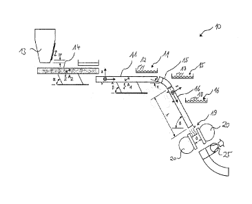
The device 10 shown in Figure 1 is intended for pasteurizing
and/or sterilizing particulate material such as a spice, sesa-
me, almonds or peeled pistachios. It contains a dosing device
13 with which the material can be dosed onto a second vibrat-
ing surface 14. The second vibration surface 14 is horizontal-
ly aligned and level (if the device 10 is installed as intend-
ed). It can be excited to vibration with a frequency f2 and an
amplitude A2 which runs at an angle a to the horizontal plane
(if the device 10 is properly installed). With the aid of this
second vibration surface 14, the throughput of the material
can be controlled and pre-separation can also take place.
Downstream of the second vibration surface 14, the device 10
contains a horizontally aligned first vibration surface 11,
which can be excited to vibrations with a frequency of fi and
an amplitude of Ai at an angle p to the horizontal plane. This
allows the material to be conveyed further downstream and sep-
CA 03036921 2019-03-14
PBHCT0541/0 / 11.03.2019 18 ---
application text.DOCX
arated. The first amplitude fl of the first vibration surface
11 is greater than the second amplitude f2 of the second vibra-
tion surface 14, which favours further separation. The first
vibrating surface 11, in contrast to the first vibrating sur-
face 14, contains a large number of channels 12 in which the
material can be conveyed and separated. These channels 12 are
shown in Figure 1 in an insert showing the first vibration
surface 11 in a sectional plane perpendicular to the direction
of flow. The profile of gutters 12 has a straight central sec-
tion with a width of 7,5 mm and two lateral sections extending
obliquely upwards from the central section at an angle of 45 .
The lateral sections of neighboring channels 12 meet at one
edge. Two adjacent edges have a distance of 16.5 mm.
Downstream of the first vibration surface 11, the device 10
has a deflection surface 15. This is designed and arranged in
such a way that the material is deflected onto it and can
slide from the first vibration surface 11 to a sliding surface
16 described below. The deflection surface 15 also contains a
large number of gutters 17, which are designed and arranged in
such a way that the material can slide in them. The deflection
surface 15 and its gutters 17 are matched to the material and
the first vibration surface 11 in such a way that the parti-
cles of the material are essentially guided downstream on a
parabolic path on which they would also fall solely due to the
action of gravity. At the upstream end of the deflecting sur-
face 15, this has an initial inclination y. This allows a
guidance and further separation of the particles of the mate-
rial. The profile of the gutters 17 shown in a further insert
also has a straight central section with a width of 7.5 mm and
two lateral sections extending obliquely upwards from the cen-
tral section at an angle of 45 . The lateral sections of
neighboring gutters 17 meet at one edge. Two adjacent edges
have a distance of 16.5 mm.
cp, 03036921 2019-03-14
PBHCT054W0 / 11.03.2019 19 ---
application text.DOCX
The aforementioned sliding surface 16, located downstream of
the deflecting surface 15, is inclined with respect to a hori-
zontal at an angle 5, which in the case of spices is advanta-
geously 600. The sliding surface 16 also has a large number of
gutters 18, which are designed and arranged in such a way that
the material can slide in them. The profile of the gutters 18
shown in a further insert also has a straight central section
with a width of 7.5 mm and two lateral sections extending
obliquely upwards from the central section at an angle of 450.
The lateral sections of neighboring gutters 17 meet at one
edge. Two adjacent edges have a distance of 16.5 mm.
Further downstream, the device 10 contains a treatment zone
19, where the material is pasteurized and/or sterilized freely
falling by means of an electron beam generated by two opposing
electron sources 20.
The device 10 also contains a suction device 25 with which
process gas, which surrounds the material, can be sucked off
downstream of the treatment zone 19.
The following steps are performed for pasteurizing and/or
sterilizing particulate material using this device 10:
By means of the second vibration surface 14 the throughput of
the material is controlled and pre-separation takes place. In
one step a) the material is conveyed and separated in the
troughs 12 of the first vibration surface 11. By means of the
electron sources 20 an electron beam is generated in one step
b). In step c), the free-falling material is then pasteurized
and/or sterilized by means of the electron beam in treatment
zone 19.
In the case of spices, the material moves advantageously
through treatment zone 19 at a speed of 2.5 m/s. This speed
can be adjusted by the length and angle of inclination of the
CA 03036921 2019-03-14
PDHCT054W0 / 11.03.2019 20 ---
application text.DOCX
sliding surface 17. The electrons of the electron beam have an
energy in the range of 80 key to 300 key, for example 250 key.
In treatment zone 19, the electron beam has an average current
density in the range 1015 s-1-cm-2 to 2,77=1015 s-'cm-2. The ma-
terial is exposed to the electron beam for a treatment time in
the range of 5 ms to 25 ms, for example 15 ms. This exposes
the material to a radiation dose in the range from 1 kGy to 45
kGy, which may be 12 kGy, for example. After pasteurization
and/or sterilization in treatment zone 19, the process gas
surrounding the product is extracted by means of suction de-
vice 25 at a preferred extraction speed which is 1 to 1.5
times the speed of the product during pasteurization and/or
sterilization.
Figure 2 shows a detailed view of treatment zone 19. In the
area of treatment zone 19, device 10 has a cassette 24 ar-
ranged between exit windows 32 of electron sources 20, a sec-
tion of which is shown in more detail in Figure 3. The cas-
sette 24 is inserted in a cassette holder 37. The cassette 24
contains two film holders 35 for one titanium protective film
23 each, which are partially permeable to the electron beams.
The cassette 24 contains several boundary surfaces 38, which
together with the protective films 23 bound a good channel 21
in which the good can be pasteurized and/or sterilized by
means of electron beams. Furthermore, the device 10 contains
two secondary channels 22 in the area of the treatment zone
19. In the operating position shown in Figure 2, these are
bounded by boundary surfaces 38 of the cassette 24, the pro-
tective foil 23 and the exit windows 32 of the electron
sources 20, which are not shown in Figure 3, and thus run be-
tween the good channel 21 and the electron sources 20. The
good channel 21 is fluid-separated from the secondary channels
23, inter alia by the protective foil 23.
cp, 03036921 2019-03-14
PBHCT054W0 / 11.03.2019 21 ---
application text.DOCX
Air can be introduced through inlet openings 30, which can
flow through the secondary channels 23 parallel to the flow
direction of the material. Downstream, the air can escape from
outlet openings 31 again. On the one hand, this air flow ena-
bles the removal of ozone, which is generated by the electron
beams, and on the other hand, it enables the cooling of the -
electron sources 20 and in particular their exit windows 32.
Figure 3 shows a still detailed, cut and perspective view of
cassette 24, in which the good channel 21, the two secondary
channels 22 and the two protective foils 23 are visible. The
good channel 21 is fluid-separated from the secondary channels
22 by the two protective foils 23. The protective films 23 are
held by means of a respective clamping element 33, which form
part of the film holder 35. On each side of the cassette 24
facing away from the good channel 21, a recess 34 is formed,
which is closed in the operating position of the device 10 by
exit windows 32 of the electron sources 20 and through which
the electron beams can penetrate.
Figure 4 shows a part of the treatment zone 19 with the elec-
tron sources 20 and the cassette 24. The downstream end of the
sliding surface 17 not shown here penetrates the opening 36
when the device 10 is mounted and is connected to the good
channel 21. The electron sources 20 are arranged in such a way
that they can be swivelled relative to the cassette holder 37
that they can be moved away from the cassette 24. In this way,
the cassette 24 is easily accessible, especially if the pro-
tective foils 23 are dirty or damaged. The protective film 23
can be detachably attached to the film holder 35.