Note: Descriptions are shown in the official language in which they were submitted.
1
A device for measuring electric current
Specification
The invention is about a device for measuring electric current, which
comprises a
plurality of magnetic field sensor elements positioned along one or more
continuous
closed paths encircling a current carrying conductor, where each sensor
element is
sensitive to one vector component of the magnetic field generated by the
electric
current, where the vector direction of sensitivity for each sensor element is
oriented
to be tangential with the closed path at each sensor location, where each
sensor
element generates an output signal, where the output signal of each sensor
element
is amplified by an element-specific gain factor, where the amplified output
signals of
the sensor elements are electronically combined to form the measurement signal
representing a value proportional to the current flowing in the current
carrying
conductor.
The invention thus relates to galvanically isolated current sensors that are
based on
configurations (arrays) of several magnetic field sensor elements that are
grouped
around the current carrying conductor. Their output signals are electronically
combined to form the measurement output signal of the current sensor.
Known current sensors that are based on magnetic cores, like current
transformers
or open or closed loop Hall-effect transducers, are characterized by a large
volume,
weight and cost due to the relatively large involved masses of the magnetic
iron core
and the secondary copper-wire winding. Further, conventional current
transformers
are not able to measure pure DC-currents.
US 7164263 B2 shows a configuration of equidistant magnetic field sensor
elements
on closed paths around the conductor, which have equal sensitivities and are
aligned
in two groups either parallel or antiparallel to the path direction. Their
output signals
CA 3037535 2019-03-21
2
are added with different polarities in the sensor electronics, thus ensuring
that the
current sensor has a low offset.
In the "conventional" sensors the magnetic core is used for performing the
line integration
of the magnetic field on a closed loop around the conductor, which will be a
good
representation of the enclosed current. However, this can be also achieved to
some extent
by using an array of small linear magnetic field sensor elements that are
located on a
closed path (e.g. on a circle) around the conductor and have their sensitive
axes aligned
along this path, if their output-signals are electronically added together to
form the output
signal of the actual current sensor. In this way the magnetic core material
and the
secondary winding can be avoided, which results in a sensor of much lower
weight for the
same dimensions.
A disadvantage of the sensor arrays is however, that both due to the discrete
positions
of the elements and to the individual deviations of their positions,
orientations and
sensitivities the line integration of the magnetic field around the conductor
will be always
imperfect. This will result in some sensitivity also to close-by currents that
pass the loop
on its outside. This can especially lead to magnetic crosstalk in multi-phase
arrangements or in other cases where there are nearby currents, for example
eddy
currents that are generated in the walls of a metallic cabinet.
It is the objective of the current invention to provide a device for measuring
electric
current with a minimized magnetic crosstalk from external currents.
According to an aspect of the present invention there is provided a device for
measuring
electric current, which comprises a plurality of magnetic field sensor
elements positioned
along one or more continuous closed paths encircling a current carrying
conductor,
where each sensor element is sensitive to one vector component of the magnetic
field
generated by the electric current, where the vector direction of sensitivity
for each sensor
element is oriented to be tangential with a corresponding one of the one or
more
continuous closed paths at each sensor location, where each sensor element
generates
an output signal, where the output signal of each sensor element is amplified
by an
element-specific gain factor, where the amplified output signals of the sensor
elements
are electronically combined to form the measurement signal representing a
value
proportional to the current flowing in the current carrying conductor
Date Recue/Date Received 2023-08-16
2a
wherein at least one sensor element on a corresponding one of the one or more
continuous closed paths has a sensitivity which is different from the
sensitivities
of the other sensor elements on the same path, or wherein the output signal of
at
least one sensor element on a corresponding one of the one or more continuous
closed paths is amplified with a different gain factor than the other sensor
elements on the same path before the sensor signals are combined to form the
measurement signal, and/or wherein the sensor elements are unequally spaced
along the length of each closed path, so that the current measuring device has
a
much reduced crosstalk sensitivity with respect to certain current paths
wherein there are more than one continuous closed paths on which magnetic
field sensor elements are positioned, wherein at least one of the paths, an
inner
path, is positioned closer to the current carrying conductor than a second
path,
an outer path, positioned more remotely from the conductor, and wherein the
output of the sensor elements on the inner and outer path are combined in such
a way, that at currents flowing through the conductor with an amplitude below
a
predeterminable threshold the measurement output signal is mostly determined
by the signals of the sensor elements positioned on the inner path, while at
currents flowing through the conductor with an amplitude above a
predeterminable threshold the measurement output signal is mostly determined
by the signals of the sensor elements positioned on the outer path.
According to an aspect of the present invention there is provided a device for
measuring
electric current in a multi-conductor configuration comprising more than one
current
carrying conductors, wherein each conductor is provided with a device as
described
herein, wherein the current in a conductor is measured by combining the signal
outputs
of the sensor element arrays related to different conductors in order to
decouple the
effects of the different currents and to improve crosstalk rejection and
measurement
accuracy.
According to the invention, at least one sensor element on a closed path has a
sensitivity
which is different from the sensitivities of the other sensor elements on the
same path, or
the output signal of at least one sensor element on a closed path is amplified
with a
different gain factor than that of the other sensor elements on the same path
before the
sensor signals are combined to form the measurement signal, and/or the sensor
elements
are unequally spaced along the length of each closed path. Such a device for
measuring
Date Recue/Date Received 2023-08-16
2b
electric current has a much reduced crosstalk sensitivity with respect to
certain current
paths. In the measurement device according to the invention magnetic crosstalk
from
external currents can be minimized by the
Date Recue/Date Received 2023-08-16
3
specific design of the sensor element arrays and the specific configurations
of sensor
elements in such sensor element arrays.
The current sensor according to the invention is composed of several magnetic
field
sensor elements that are arranged on one or more closed paths around the
current
carrying conductor and have their sensitive axes aligned along these paths.
The
output signals of the elements are electronically combined to form the output
signal
of the actual current sensor.
However, in contrast to sensor designs known in the prior art, either the
positions of
the individual sensor elements are selected such that they deviate from a
uniform,
i.e. equidistant distribution on the respective path, or their sensitivities
or the gain
factors with which their output signals are added together are chosen
different from
one another.
In further designs both types of modifications may apply at the same time. In
an
advantageous embodiment, at least one sensor element on a closed path has a
sensitivity which is different from the sensitivities of the other sensor
elements on the
same path, or the output signal of at least one sensor element on a closed
path is
amplified with a different gain factor than that of the other sensor elements
on the
same path before the sensor signals are combined to form the measurement
signal,
and the sensor elements are unequally spaced along the length of each closed
path.
These modifications according to the invention are designed such, that the
crosstalk-
sensitivity of the current sensor will be especially reduced with respect to
currents in
certain conductors or groups of conductors, e.g. with respect to the other
phase
conductors in a multiphase arrangement.
In a two-dimensional arrangement of long parallel conductors, e.g. a straight
multiphase busbar system in a switchgear, where the sensor elements of the
arrays
would be arranged in a plane perpendicular to the conductors, the crosstalk
sensitivity can be designed to be especially low in one or more specific
directions,
e.g. along the intersection line between the plane of the array and the plane
of the
conductors in a planar system. This would again result in reduced crosstalk
from the
other phase currents.
CA 3037535 2019-03-21
4
By an appropriate selection of the gains and the angular positions of the
sensor
elements the current sensors can be further specifically designed to achieve
low
crosstalk sensitivity in extended ranges around the target orientation and
position/distance of the entire sensor by assuring that the crosstalk
amplitude is close
to zero and has either a minimum or a horizontal inflection point close to its
target
orientation. This is also advantageous as real conductors have finite cross
section
and the current distributions may vary as a function of the frequency due to
eddy
current and proximity effects.
Aa advantage of the solution according to this invention is that by applying
the
conceptions of the invention it is possible to design current sensors which
combine
the advantages of sensors with complete magnetic field integration, i.e. low
magnetic
crosstalk, with those of sensor arrays, i.e. low volume and weight. Further,
the
crosstalk-amplitude will remain at a low level even if the current sensor is
slightly
misaligned with respect to conductors which carry interfering currents.
The current sensor according to the invention is composed of a multitude of
magnetic
field sensor elements that are arranged on one or more closed paths around the
conductor carrying the current I to be measured.
According to an advantageous embodiment, the field sensor elements may be
based
on Hall effect, magnetoresistive effects or on inductive principles.
According to another advantageous embodiment, the sensitive directions of the
uniaxial elements may be oriented in parallel or anti-parallel to the local
path direction
and individual elements on the same path may have different sensitivities or
their
output signals are amplified by different gain factors before they are
combined to
form the sensor signal.
According to an advantageous embodiment, the individual elements are non-
evenly
distributed along the paths. In an advantageous embodiment, the sensor element
configuration has a higher element concentration in the vicinity of a certain
sensor
axis. Such a sensor axis is for example the x-axis or the y-axis of a
Cartesian
coordinate system, in which the x- and the y- axes define the plane in which
the
closed paths of the sensor elements are positioned, and the current carrying
conductor interceps this plane, and at the point of interception the direction
of the
conductor defines the z-axis of the coordinate system.
CA 3037535 2019-03-21
5
The output signals of the individual sensor elements are electronically
combined to
generate the output signal of the current sensor.
The measurement device operated as a current sensor according to the invention
has a much reduced crosstalk sensitivity with respect to certain current
paths.
According to an advantageous embodiment of the invention, the sensor elements
have both different sensitivity (gain factor) and are non-evenly distributed
along the
path(s). For example, according to an advantageous embodiment, the sensor ele-
ments have a higher element concentration, in the vicinity of a certain sensor
axis,
which means a lower distance of the elements from this sensor axis.
According to a preferred embodiment, the paths on which the sensor elements
are
arranged are preferably mostly parallel to the field of the magnetic current
to be
measured. This means the path circulation direction is close to the main
magnetic
field direction.
In an advantageous embodiment, the paths have circular, elliptic or nearly
rectangu-
lar shape.
In an advantageous embodiment, configuration of the sensor elements
(positions,
sensitivities and gain factors) is mirror symmetrical with respect to its X-
axis.
In an advantageous embodiment, configuration of the sensor elements
(positions,
sensitivities and gain factors) is mirror symmetrical with respect to its Y-
axis.
An advantage of the device according to the invention is that crosstalk is
especially
reduced with respect to certain current paths (e.g. in 2-dimen-sional
configurations
with respect to conductors at a certain angular position with respect to the
sensor
array)
Particularly, crosstalk sensitivity is reduced in extended ranges around the
target on-
entation, possibly also the position/ distance, of the entire sensor by
assuring that the
crosstalk amplitude is close to zero and has either a minimum or a horizontal
inflec-
tion point close to its target orientation.
Appropriate parameters, such as individual gains and angular positions of the
sensor
elements, for achieving this goal can be either determined based on trial and
error or
by means of optimization calculations, e.g. by minimizing a suited cost
function of the
CA 3037535 2019-03-21
6
crosstalk and its derivatives as a function of the deviations from the regular
array
configuration (with equal gains and equidistant elements) for suited boundary
condi-
tions.
Different paths contain elements with different sensitivities (e.g., different
types of
sensors).
In an advantageous embodiment, sensor elements on outer paths have lower sensi-
tivity than elements on inner paths
For maximizing the dynamic range of the sensor the output of the inner and the
out-
er elements are combined in such a way, that at low currents the sensor output
sig-
nal is mostly determined by the signals of the inner elements, while above a
certain
current amplitude a switchover to the outer elements will take place. By this
a large
SNR and a linear sensor characteristic will be always maintained. The
switchover
may be abrupt or gradual, when the current amplitude is increased
In another advantageous embodiment, placement of the sensor elements on the
dif-
ferent paths around the current carrying conductor is made in such a way that
linear
arrays are formed in the radial directions which are composed of an even
number of
elements and which are symmetrical with respect to the axis of the conductor
as-
suming that the latter has a symmetrical cross section
In this case, the selection of the gain factors and polarities allocated to
the different
elements of the linear arrays is done such that in the current range in which
all of the
elements will deliver a sufficiently large and linear output signal the effect
of the low
order magnetic field components in the space-coordinates will be reduced in
the
output signal of the current sensor. This also results in a reduction of
magnetic
crosstalk from remote sources of the magnetic field
Measures are taken for the individual calibration of the sensitivity and the
offset of
the elements in order to reduce the influences of sensor tolerances on the
crosstalk
sensitivity of the current sensor
According to an advantageous embodiment the sensor has an even number of ele-
ments of each type.
According to an advantageous embodiment one half of the elements of each type
has their sensitive axes oriented in parallel, the other half anti-parallel to
the path
CA 3037535 2019-03-21
7
circulation, while only the output signals of the second half are inverted
before they
are combined to form the output of the current sensor. In this way the similar
offsets
of the elements of the same type, which may further be temperature dependent,
will
be essentially eliminated or at least reduced by a pair- or group-wise
subtraction of
the elements' output signals.
The outputs of the individual elements are combined according to their
respective
polarities before the output signals of the groups are combined to form that
of the
current sensor.
According to an advantageous embodiment, the current sensor includes other
measures for the electronic compensation of the sensitivity- and offset-drift
of the el-
ements, e.g. by using electronic circuits with temperature dependent resistors
or by
performing compensation based on temperature measurements with other sensors.
Calibration of the sensitivities of the individual elements, generation of the
output sig-
nal of the current sensor, compensation of offset and the temperature drifts
of offset
and sensitivity, application of weight factors and formation of the output
signal are
performed by analog trimming devices and analog electronic circuitry, which
may be
based on adders and amplifiers that use operational amplifiers
Calibration of the sensitivities of the individual elements, generation of the
output sig-
nal of the current sensor, compensation of offset and the temperature drifts
of offset
and sensitivity, application of weight factors and formation of the output
signal are
performed by a simultaneous ND-conversion of the output signals of the
individual
elements and by the application of suited digitally stored offset- and gain
corrections,
weight factors, temperature corrections and summations in the digital domain
by
means of a calculation unit, for example a microcontroller or similar, which
forms the
corrected output signal of the current sensor.
In multi-conductor applications, the current in a conductor may be measured by
com-
bining the outputs of the sensor arrays belonging to different conductors in
order to
decouple the effects of the different currents and to improve crosstalk
rejection and
measurement accuracy.
According to an advantageous embodiment the sensor is mounted such that its ax-
is/direction of reduced crosstalk-sensitivity is pointing into the direction
of the
CA 3037535 2019-03-21
8
source(s) of magnetic interference fields, e.g. by an alignment of the sensor
axes (X,
Y, Z) with those (X', Y', Z') of a three-phase conductor system (where X' is
in the di-
rection of the shortest connection between the straight conductors that extend
in the
Z'-direction)
The invention and further embodiments of the invention and further advantages
of
the invention will now be explained with reference to the figures.
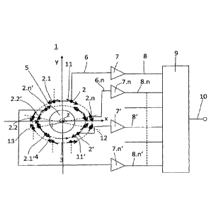
Figure 1 shows a device for measuring electric current according to a first
embodiment of the invention;
Figure 2 shows a sensor array according to the invention in a linear 3-phase
conductor configuration;
Figure 3 shows a polar plot of the crosstalk sensitivity of a circular array
for a
perpendicular line current.
Figure 1 shows a device 1 for measuring electric current I in a current
carrying
conductor 5. The device 1 comprises a plurality of magnetic field sensor
elements.
The magnetic field sensor elements are represented by dots. In the exemplary
embodiment of figure 1 there are shown 16 such field sensor elements. For
reason of
clearness only 8 of them are specified with reference numerals 2, 2.1,
2.2,..., 2.n; 2',
2.1', 2.2',..., 2.n'. These are positioned along two continuous closed paths
3, 4
encircling the current carrying conductor 5. One of the paths, path 4, is
positioned
closer to the current carrying conductor 5 than the other path 3, which is
positioned
more remotely from the conductor 5. Eight of the field sensor elements are
positioned
on the inner path 4, and eight of the field sensor elements are positioned on
the outer
path 3.
The magnetic field sensor elements can be based on any known magnetic sensor
principle, for example on Hall effect or magnetoresistive effects or inductive
principles.
Each sensor element 2, 2.1, 2.2,..., 2.n; 2', 2.1', 2.2',..., 2.n' is
sensitive to one vector
component of the magnetic field generated by the electric current I flowing in
the
conductor 5. The vector direction of sensitivity for each sensor element 2,
2.1, 2.2,...,
2.n; 2', 2.1', 2.2',..., 2.n' is indicated by an arrow and is oriented to be
tangential with
the closed path 3, 4 at each sensor location. For reason of clearness only two
of the
CA 3037535 2019-03-21
9
arrows are specified with a reference numeral, and these are the arrows 11 for
sensor element 2 and 11' for sensor element 2'. Arrow 11 points in anti-
clockwise
direction, whereas arrow 11' points in clockwise direction. This illustrates
that sensor
elements can differ in type and/or sensitivity, particularly compared to the
sensor
elements positioned on the other paths. Particularly, the sensitive directions
of the
magnetic field sensor elements may be parallel or anti-parallel to the local
path
direction of the paths 3, 4.
In the exemplary embodiment show here, one half of the sensor elements of each
type has their sensitive axes oriented in parallel, the other half anti-
parallel to the
direction of the magnetic field generated by the current carrying conductor5.
Each sensor element generates an output signal. Exemplary only four output
signal
lines 6, 6.n, 6', 6n' are shown in the figure, whereby it is understood that
each sensor
element is connected to an output signal line, even if not shown here in the
figure.
The output signal of each sensor element is amplified by an amplifier with an
.. element-specific gain factor. Here in the exemplary embodiment each output
signal
line 6, 6.n, 6', 6.n' is associated with its own amplifier 7, 7.n, 7', 7.n'.
The amplified
output signals of the sensor elements are electronically combined to form the
measurement signal 10 representing a value proportional to the current I
flowing in
the current carrying conductor 5. Electronic combination is achieved by means
of an
electronic circuitry 9 which has as input the signal lines carrying the
amplified output
signals, and has as output a signal line carrying the measurement signal 10.
For
reasons of clearness, only four of the output signal lines 8, 8.n, 8', 8.n'
are specified
with reference numerals, and only six such output signal lines are shown in
the
figure, whereas it is understood that there is for each of the sensor elements
an
output signal line representing its output, even if not all of them are shown
in the
figure.
In the exemplary example shown here, the output signals of the anti-parallel
oriented
sensor elements may be inverted before the output signals of the sensor
elements
are combined to form the measurement signal 10.
At least one sensor element, for example the sensor element 2 on the outer
path 3
has a sensitivity which is different to the sensitivities of the other sensor
elements on
the same path 3. The output signal 6 of at least one sensor element 2, for
example
CA 3037535 2019-03-21
10
on the outer path 3, is amplified with a different gain factor than the other
sensor
elements on the same path 3 before the sensor signals are combined to form the
measurement signal 10. This is to say, the magnetic field sensor elements may
have
different gains or sensitivities. Different gains are needed to achieve a
direction-
sensitive crosstalk-reduction, which is a desirable advantage of the device
according
to the invention.
In addition, at least one sensor element can have a different sensitive
direction. The
difference in sensitive direction can be used to compensate offset.
In addition, or as an alternative, as can be seen in the figure, magnetic
field sensor
elements can be unequally spaced along the length of each closed path 3, 4.
The advantageous effect of a sensor element arrangement as shown and described
in the figure is that the current measuring device 1 can be designed to have a
much
reduced crosstalk sensitivity with respect to certain current paths.
It can be seen in figure 1 that the sensor elements and the two paths 3, 4 are
arranged in a first plane, wherein close to the point of intersection of the
conductor 5
with this plane the direction of the conductor 5 is perpendicular to the
drawing plane.
The first plane is defined through a first and a second axis x, y of a
Cartesian
coordinate system with the vector showing in the direction of the conductor 5
at the
point of intersection defining the third axis, the z-axis. In figure 2 it can
also be seen
that in the first plane there is a higher sensor element concentration in the
vicinity of
the x-axis as compared to the y-axis. In addition, in the exemplary embodiment
shown in figure 1 the configuration of the sensor elements is mirror
symmetrical with
respect to the x-axis or to the y-axis.
The placement of the sensor elements on the different paths around the current
carrying conductor is made in such a way that linear arrays or groups of
sensor
elements are formed in directions extending radially from the conductor. In
the
exemplary embodiment shown in figure 1 one can see two such arrays, specified
by
reference numerals 12, 13. Said arrays 12, 13 are composed of an even number
of
elements, in the exemplary embodiment shown here there are four sensor
elements
in each array, and they are positioned symmetrically with respect to the axis
z of the
conductor 5.
CA 3037535 2019-03-21
11
In the exemplary example shown here, the sensor elements 2', 2.1', 2.2',...,
2.re
which are positioned on the inner path 4, which is closer to the current
carrying
conductor 5, have a higher sensitivity compared to the sensor elements (2,
2.1,
2.2,..., 2.n) positioned on the outer path 3 positioned more remotely from the
conductor 5.
The combination of the sensor output signals in the electronic circuitry 9 may
in the
exemplary example shown here be configured in such a way that at currents
flowing
through the conductor with an amplitude below a predeterminable threshold the
measurement output signal 10 is mostly determined by the signals of the sensor
elements 2', 2.1', 2.2',..., 2.n' positioned on the inner path 4, while at
currents flowing
through the conductor 5 with an amplitude above a predeterminable threshold
the
measurement output signal 10 is mostly determined by the signals of the sensor
elements (2, 2.1, 2.2,..., 2.n) positioned on the outer path 3.
Figure 3 shows a polar plot of the crosstalk sensitivity of a circular array
of sensor
elements around a conductor 5 in a measuring device similar to the one shown
and
explained in figure 1. It has non-equidistant elements with different gains.
Crosstalk
sensitivity is shown for a perpendicular line current, along the z-direction,
at a fixed
distance from the center of the array. It can be seen that for an appropriate
selection
of the sensitivities or gains and the sensor positions the crosstalk
sensitivity is very
low in a certain angular rang 20 around the x-axis, and is high in other
angular
ranges 22, 23. The invention allows to design a measuring device with sensor
elements positioned purposefully such that specific angular ranges of low
crosstalk
sensitivity can be achieved.
Figure 2 shows a device 100 for measuring electric current in a multi-
conductor
configuration comprising three current carrying conductors 30, 31, 32. Each of
the
conductors 30, 31, 32 can be provided with a device for measuring electric
current as
shown and explained in figure 1. Of course, also only one conductor, such as
in the
exemplary embodiment shown in figure 2 the conductor 31, can be provided with
arrays of magnetic field sensor elements as described in figure 1. The current
in a
conductor is then measured by combining the signal outputs of the sensor
element
arrays related to different conductors in order to decouple the effects of the
different
currents and to improve crosstalk rejection and measurement accuracy.
CA 3037535 2019-03-21
12
Figure 2 shows a linear 3-phase conductor configuration with conductors 30,
31, 32
and further both the magnetic field 33 of the current I in conductor 31, which
shall be
measured, and the interfering field lines 34 of the current in the closely
located
conductor 30 that may generate crosstalk in the sensor output signal. In this
example
the 16 sensor elements, indicated by dots are arranged in two circles 35, 36
that
coincide with the field lines generated by the current I in the center
conductor 31. The
sensor elements are positioned such that they also form 4 linear arrays 37,
38, 39,
40 with 4 elements in each array.
By modifying the positions or gains (sensitivities) of some of the sensor
elements in a
controlled way it is possible to achieve low magnetic crosstalk with a flat
response to
small angular deviations in selected directions with respect to the center of
the array.
This is at the cost of higher crosstalk in other directions for which it has
to be assured
that there are no high currents nearby.
The given examples are not exhaustive and there are more possibilities to
reduce the
crosstalk in certain directions by changing the angular positions and
sensitivities of
the elements in an array. Solutions can be also found if the conductors are
not
straight or are aligned in other directions.
CA 3037535 2019-03-21
13
List of reference numerals
1 Device for measuring electric current
2; 2.1; 2.2; 2.n Magnetic field sensor element
2'; 2.1'; 2.2'; 2.n' Magnetic field sensor element
3 Continuous closed path
4 Continuous closed path
Current carrying conductor
6; 6.n; 6'; 6n' Output signal
7; 7.n; 7'; 7n' Amplifier with element-specific gain function
8; 8.n; 8'; 8n' Amplified output signal
Electronic circuitry
Measurement signal
11, 11' Arrow indicating vector direction of sensor element
sensitivity
12 Linear array of sensor elements
13 Linear array of sensor elements
Angular range with low crosstalk sensitivity
21 Angular range with low crosstalk sensitivity
22 Angular range with high crosstalk sensitivity
23 Angular range with high crosstalk sensitivity
Conductor
31 Conductor
32 Conductor
33 Magnetic field of conductor 31
34 Interfering magnetic field lines of conductor 30
Outer circular path on which sensor elements are aligned
36 Inner circular path on which sensor elements are aligned
37 Array of sensor elements
38 Array of sensor elements
39 Array of sensor elements
Array of sensor elements
CA 3037535 2019-03-21