Note: Descriptions are shown in the official language in which they were submitted.
CA 03037785 2019-03-21
WO 2018/058243 PCT/CA2017/051146
METHOD AND APPARATUS FOR PRODUCING AN ALCOHOLIC BEVERAGE
CROSS-REFERENCE TO OTHER APPLICATIONS
[0001] This is a formal application based on and claiming the benefit of US
Provisional
Application No. 62/400,905 filed September 28, 2016 which is hereby
incorporated by
reference.
TECHNICAL FIELD
[0002] The disclosure is generally directed at alcoholic beverages and more
specifically is
directed at a method and apparatus for producing an alcoholic beverage.
BACKGROUND
[0003] Beer making, or beer brewing, is a process that has been known for many
years.
The basic ingredients of beer are water; a starch source, such as malted
barley, able to be
fermented (converted into alcohol); a brewer's yeast to produce the
fermentation; and a
flavouring, such as hops, to offset the sweetness of the malt.
[0004] With many current beers, the typical brewing process results in an
alcohol
percentage of between 4.8% to 5.4%. This alcohol percentage reflects the
amount of starch
converted to alcohol in the process. While some brewers have been able to
achieve higher
alcohol percentages using various techniques, there is typically a higher cost
to being able to
achieve these percentages due to larger amounts of raw materials, longer time
of production
or the like.
[0005] Therefore, there is provided a method and system for producing an
alcoholic
beverage.
SUMMARY
[0006] The disclosure is directed at a method of producing an alcoholic
beverage. The
method described provides a beverage which has a higher alcohol by volume
percentage
than current alcoholic beverages being produced using identical ingredients,
processes and
recipes. By generating a nanobubble solution, such as a nanobubble water, and
substituting
1
CA 03037785 2019-03-21
WO 2018/058243
PCT/CA2017/051146
this into the alcoholic beverage production process, improvements to the
resultant alcoholic
beverage are realized.
[0007] In one aspect of the disclosure, use of the nanobubble solution, or
nanobubble
water, may also enhance sugar extraction from a starch source. An increased
amount of
sugar can be extracted compared with sugar extraction using regular water, and
the sugar
may be extracted in a shorter time frame. The extraction of more sugar from
the starch
source may enhance various properties and characteristics when the nanobubble
water is
used in the production of an alcoholic beverage.
[0008] In one aspect of the disclosure, there is provided a method of sugar
extraction
including heating up a nanobubble water solution and then mixing the heated
nanobubble
water solution with a starch source. The extracted sugar solution can then be
further
processed to retrieve the extracted sugar or the extracted sugar solution may
be used as a
liquid in further beverage preparation.
[0009] In another aspect of the disclosure, there is provided a method of
producing an
alcoholic beverage by using a nanobubble water instead of regular water during
the
production process.
[0010] In a further aspect of the disclosure, there is a method of producing a
nanobubble
water for use in the production of an alcoholic beverage or in sugar
extraction.
[0011] In one aspect of the disclosure, there is provided a method of
producing an
alcoholic beverage including generating a nanobubble solution; mixing the
nanobubble
solution with a mash solution to produce a nanobubble and mash mixture;
lautering the
nanobubble and mash mixture to produce a wort; boiling the wort; fermenting
the boiled wort;
conditioning the fermented mixture; and filtering the conditioned mixture.
[0012] In another aspect, generating a nanonbubble solution includes passing a
liquid
through a nanobubble generating apparatus. In a further aspect, the liquid is
water. In yet
another aspect, the nanobubble solution is heated before mixing the nanobubble
solution
with the mash solution. In yet another aspect, the nanobubble and mash mixture
is heated
prior to lautering the wort. In another aspect, lautering includes separating
grains from the
wort.
[0013] In another aspect of the disclosure, there is provided an apparatus for
producing an
alcoholic beverage including a nanobubble solution producing apparatus; an
apparatus for
2
CA 03037785 2019-03-21
WO 2018/058243 PCT/CA2017/051146
providing a mash solution; and a mixing vessel for mixing the nanobubble
solution and the
mash solution.
[0014] In a further aspect, the nanobubble solution producing apparatus
includes a
nanobubble generator. In another aspect, the nanobubble solution production
apparatus
further includes a liquid source connected to an inflow end of the nanobubble
generator. In
yet another aspect, the nanobubble solution production apparatus further
includes a reservoir
for collecting the nanobubble solution at an outflow end of the nanobubble
generator. In yet
a further aspect, the system includes a heating apparatus for heating the
mixing vessel.
[0015] In another aspect of the disclosure, there is provided a method of
sugar extraction
including producing a nanobubble solution; heating the nanobubble solution;
and mixing the
heated nanobubble solution with a starch source.
[0016] In a further aspect, the nanobubble solution is heated after being
mixed with the
starch source.
DESCRIPTION OF THE DRAWINGS
[0017] The following figures illustrate various aspects and preferred and
alternative
embodiments of the disclosure.
[0018] Figure 1 is a schematic diagram of apparatus for producing an alcoholic
beverage;
[0019] Figure 2 is a perspective view of one embodiment of a nanobubble
generator;
[0020] Figure 3a is a perspective view of a part of the nanobubble generator
of Figure 2;
[0021] Figure 3b is a longitudinal cross-sectional view of the nanobubble
generator of
Figure 2;
[0022] Figure 4 is a side view of a treatment portion of the nanobubble
generator;
[0023] Figure 5 is a perspective view of the treatment portion of Figure 4;
[0024] Figure 6 is a front view of a disc-like element of the nanobubble
generator;
[0025] Figure 7 is an enlarged view of a longitudinal cross-section of the
nanobubble
generator;
[0026] Figure 8 is a schematic diagram of a system for generating a nanobubble
solution;
[0027] Figure 9 is a schematic diagram of another embodiment of a system for
generating
a nanobubble solution;
[0028] Figure 10 is a flowchart outlining a method of producing an alcoholic
beverage with
a nanobubble solution; and
3
CA 03037785 2019-03-21
WO 2018/058243
PCT/CA2017/051146
[0029] Figures 11a to 11d are charts outlining experimental data.
DETAILED DISCLOSURE
[0030] The disclosure is directed at a method and system for producing an
alcoholic
beverage. The method includes using a nanobubble solution, such as nanobubble
water
instead of regular water (such as well water) in the process. Use of the
nanobubble solution
was shown to increase the alcohol by volume (ABV) percentage of the resultant
beverage by
replacing the water with nanobubble water and using the same ingredients.
Alternatively, a
reduced amount of ingredients may be used to produce a similar ABV% using
conventional
processes.
[0031] In another aspect of the method, use of the nanobubble water also
results in an
increased level of sugar extraction during the production process. The sugar
extraction also
occurred in a shorter time frame than current methods of sugar extraction.
This novel
method of sugar extraction may also be considered for other applications where
sugar
production or extraction from a starch source is being performed or
beneficial. Although
described as being used in the process of producing an alcoholic beverage, the
sugar
extraction may also be used in other applications where sugar is being
extracted from a
starch source.
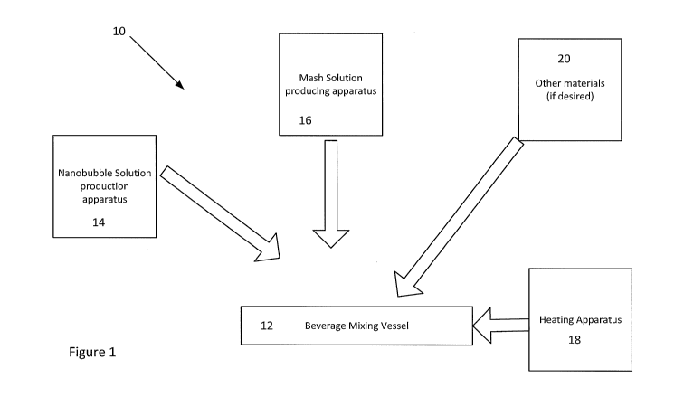
[0032] Turning to Figure 1, a schematic diagram of apparatus for producing an
alcoholic
beverage is shown. The apparatus 10 includes a beverage mixing vessel 12 such
as a keg,
however, it will be understood that any container in which materials can be
mixed is suitable.
The beverage mixing vessel 12 may include apparatus to mix the ingredients
within the
vessel as the ingredients are being added in an automated or non-automated
manner.
Alternatively, the ingredients may be mixed manually.
[0033] The apparatus 10 further includes a nanobubble solution production
apparatus 14
that generates or produces a nanobubble solution, such as nanobubble water, to
be used in
the alcoholic beverage production process. The apparatus 10 further includes
an apparatus
for producing and adding a mash solution 16 to the beverage mixing vessel 12
along with a
heating apparatus 18 for heating the beverage mixing vessel, when, or if
necessary.
[0034] The nanobubble solution production apparatus 14 may be constructed in a
variety
of different embodiments to create or generate nanobubbles in a liquid or a
liquid solution.
The nanobubble solution production apparatus may include a nanobubble
generator or any
4
CA 03037785 2019-03-21
WO 2018/058243 PCT/CA2017/051146
other type of apparatus capable of generating nanobubbles in a liquid or
liquid solution. In
another embodiment, the apparatus 14 may be connected with a source of liquid.
The
system 10 may also include apparatus for adding other materials 20 to the
beverage mixing
vessel 12. These other materials may include materials to enhance or flavor
the alcoholic
beverage.
[0035] Turning to Figures 2 to 7, schematic diagrams of a nanobubble generator
for use in
the nanobubble solution production apparatus 14 is shown. The nanobubble
generator 30 is
used to assist in the generation of the nanobubble solution (nanobubble water)
from a source
liquid, such as, but not limited to, water.
[0036] As shown in Figure 2, the nanobubble generator 30 may include a housing
32
having an inflow portion or end 34 for receiving a source solution or liquid
(i.e. water) from a
source 36, an outflow portion or end 38 for releasing the nanobubble solution
40 and a
treatment portion or area 42 between the inflow end 34 and the outflow end 38
for treating
the source liquid 36. The inflow end 34 and outflow end 38 may include a
threaded boss 44
and 46, respectively. In a preferred embodiment, the housing 32 and bosses 44
and 46 are
made of a substantially inert material, such as, but not limited to, polyvinyl
chloride (PVC). In
an embodiment, the housing 32 may take a substantially tubular form.
[0037] Turning to Figure 3a, a perspective view of a treatment apparatus is
shown. Figure
3b is a section view of the nanobubble generator 30 with the treatment
apparatus housed
therein. The treatment apparatus 50, which can be seen as a nanobubble
generating
member, includes the bosses 44 and 46 at opposite ends of the treatment
apparatus and a
generally elongated member 52 between the two bosses 44 and 46. As can be seen
in
Figure 3b, the elongated member 52 is preferably housed within the housing 32
with the
bosses 44 and 46 extending out of the housing 32.
[0038] With reference to Figures 4 to 7, the treatment apparatus 50 of the
nanobubble
generator 30 may include a series of sequential cavitation zones 54 and shear
surface
planes 56. The series of sequential cavitation zones 54 and shear surface
planes 56 may be
enabled by having the generally elongated member 52 having a series of two or
more
spaced apart elements 58 which extend axially through the housing 32 and may
be
interposed between the inflow 34 and the outflow 38 ends, or portions of the
nanobubble
generator 30. In one embodiment, between two (2) and thirty (30) spaced apart
elements 58
may be used while in another embodiment, more than thirty (30) spaced apart
elements 58
CA 03037785 2019-03-21
WO 2018/058243 PCT/CA2017/051146
may be used. It will be understood that any number of spaced apart elements 58
may be
used.
[0039] The elements 58, which in a preferred embodiment, are disc-shaped, may
be
supported upon or mounted on a central rod or shaft 60 of the elongated member
52. With
reference to Figure 7, each element 58 may include opposite walls 60 and 62
(also referred
to as shear walls) and a peripheral or side wall 64. One shear wall 60 may
face the inflow
end and the opposite shear wall 62 may face the outflow end 38 of the
nanobubble generator
10. The peripheral wall 64 may extend between opposite shear walls 60 and 62.
The disc-
like elements 58 may be held in spaced relation to each other and may be
separated from
one another by a space 66.
[0040] Furthermore, each element 58 is preferably formed with at least one
groove or
notch 68 extending downwards from its peripheral wall 64. Each groove or notch
68 may
include edges or shear edges 70 and a shear surface plane 56 between the shear
edges 70.
The shear surface plane 56 may be viewed as a continuation of the peripheral
wall 64 into
the groove or grooves 68. The edges 70, which may have a scallop design, may
be
substantially sharp as to be able to shear the liquid passing through the
nanobubble
generator 30.
[0041] In one embodiment, the disc-like elements 58 may be laser cut and may
be
manufactured from a single metal. Preferably the disc-like elements may be
made of a
corrosion resistant metal. More preferably, the disc-like elements 58 may be
made from
stainless steel 300 series, such as 316L.
[0042] As illustrated in Figure 4, in a preferred embodiment, a width of each
disc-like
element 58 can be seen as "a" and therefore a width of the shear plane surface
is preferably
about one half the distance "b" or space 66 between two consecutive disc-like
elements 58.
[0043] As further illustrated in Figures 4 to 7, the axially successive discs
58 are arranged
along the rod 60 with their notches or grooves circumferentially staggered in
relation to one
another. The elements 58 may be arranged on the rod 60 such that the notches
68 of
adjacent elements 58 are in an alternating pattern. That is, if a notch in one
disc-like element
58 is facing down, the notch in the following, or adjacent, disc-like element
is facing up.
[0044] As shown in Figure 7, each disc-like element 58 may be disposed
substantially
perpendicular to the flow of the liquid solution within the housing 32, such
that the elements
58 may substantially block any direct fluid flow through the housing 32 and as
a result the
6
CA 03037785 2019-03-21
WO 2018/058243 PCT/CA2017/051146
fluid flow is directed to pass through, over, or by, the notches, grooves or
apertures 68 of the
elements 58. Due to the alternating arrangement of the grooves 68, the fluid
flow between
the elements 58 is turbulent and by virtue of the differing cross-sectional
areas of the
grooves 68 in each element 58, the width of the elements, and the space 66
between the
elements 58, the liquid is caused to accelerate and decelerate on its passage
through the
housing 32 to ensure a turbulent flow over the surfaces of the elements 58.
The nanobubble
generator may be unidirectional and unipositional as shown by the arrows in
Figures 2 and 7.
[0045] Figure 8 shows a first embodiment of a nanobubble solution production
apparatus
14 for producing nanobubbles in a liquid. The liquid is preferably provided by
the liquid
source 36. In one embodiment, the apparatus 14 may include an optional source
liquid pre-
treatment system 74, a first nanobubble generator 75, an optional high zeta
potential crystal
generator 76, an optional pre-filtration system 78, an optional at least one
filtration device 80,
and an optional second nanobubble generator 82. The apparatus 14 may also
include a
pump 84 and a storage container 86. The pre-treatment system 74, the first
nanobubble
generator 75, the zeta potential shift crystal generator 76, the pre-
filtration system 78, the
filtration device 80 and the second nanobubble generator 82 are preferably in
liquid
communication with one another and are connected by way of a conduit system.
The conduit
system may include, for example, pipes, hoses, tubes, channels, and the like.
[0046] The liquid for the source liquid 36, such as water, well water or tap
water, is
supplied from any suitable source (for example a faucet) and the liquid may be
stored in a
reservoir 88. Examples of the source reservoir 88 may include, but are not
limited to, steam
boilers, water heaters, cooling towers, drinking water tanks, industrial water
supply
reservoirs, and the like. Source liquid may be added continuously or
intermittently to liquid
reservoir 88. Alternatively, the liquid may be supplied continuously or
intermittently from any
source. The composition of source liquid may be tested and, if necessary,
additional minerals
and other constituents may be added to provide a sufficient source for
generation of
nanobubbles. The source liquid may also be treated, prior or subsequent being
held in the
reservoir 88 by pre-treatment system 74 to substantially remove unwanted
contaminants that
may interfere with the treatment process, such as, but not limited to, debris,
oil-containing
constituents, and the like.
[0047] In operation, the liquid solution preferably flows through either or
both of the first
and second nanobubble generators 75 and 82 with enough force and pressure to
initiate an
7
CA 03037785 2019-03-21
WO 2018/058243 PCT/CA2017/051146
endothermic reaction to create the nanobubbles with paramagnetic attributes.
The pump 84
may be used to generate this force and pressure. Although not shown, other
pumps may be
located within the apparatus 14 to assist in generating adequate pressure for
passing the
source liquid through either nanobubble generator. As such, the liquid
solution may be
actively pumped towards either nanobubble generator. The treated liquid 40 can
then be
released using a passive system, such as located in a plume to treat the water
before a
water turbine or propeller.
[0048] As shown in Figure 8, before reaching the at least one filtration
device 80, the
treated liquid may optionally be passed through a zeta potential crystal
generator 76. High
zeta potential crystal generators are known in the art and generally useful
for the prevention
or reduction of scaling. The high zeta potential crystal generator 76 may
increase zeta
potential of crystals by electronically dispersing bacteria and mineral
colloids in liquid
systems, reducing or eliminating the threat of bio-fouling and scale and
significantly reducing
use of chemical additives.
[0049] As further shown in Figure 8, after passage through the first
nanobubble generator
75 and the optional high zeta potential crystal generator 76, and before
reaching the optional
filtration device 80, the liquid may optionally be passed through the pre-
filtration system 78,
wherein minerals, such as iron, sulphur, manganese, and the like are
substantially removed
from the treated source liquid. Pre-filtration system 78 can be, for example,
a stainless steel
mesh filter. If necessary, or desired, the liquid output of the first
nanobubble generator 75
may be passed through the at least one filtration device 80. In a preferred
embodiment,
filtration device 80 reduces, substantially reduces or eliminates bacteria,
viruses, cysts, and
the like from the treated liquid. Any filtration devices known in the art may
be used. Filtration
device 80 may include, but is not limited to, particle filters, charcoal
filters, reverse osmosis
filters, active carbon filters, ceramic carbon filters, distiller filters,
ionized filters, ion exchange
filters, ultraviolet filters, back flush filters, magnetic filters, energetic
filters, vortex filters,
chemical oxidation filters, chemical addictive filters, Pi water filters,
resin filters, membrane
disc filters, microfiltration membrane filters, cellulose nitrate membrane
filters, screen filters,
sieve filters, or microporous filters, and combinations thereof. The treated
and filtered liquid
may be stored or distributed for use and consumption.
[0050] In the embodiment shown in Figure 9, the pump 84 is provided downstream
from
the first nanobubble generator 75 and treated liquid 40 is released and
distributed
8
CA 03037785 2019-03-21
WO 2018/058243 PCT/CA2017/051146
intermittently or continuously for various liquid system applications. As
discussed above, the
pump, or another pump, may be provided upstream from the first nanobubble
generator 75.
[0051] The treated liquid, now having a high concentration of nanobubbles, may
be
distributed to and stored in a storage container 86, such as a reservoir or
directly delivered to
apparatus for alcoholic beverage production such as the mixing vessel 12 of
Figure 1. In this
embodiment, before distribution of the stored treated liquid, the stored
liquid may be passed
through the second nanobubble generator 82, for generation of additional
nanobubbles in the
treated source liquid. The twice treated liquid may then be distributed for
use in the alcoholic
beverage production process. It should be understood that the system may
include more
than two nanobubble generators to further increase the number of nanobubbles
within the
liquid solution.
[0052] Figure 9 illustrates another embodiment of a nanobubble solution
production
apparatus 14. The apparatus 14 is similar to the one shown in Figure 8 and
includes the
reservoir 88 that store the liquid 40, an optional source liquid pre-treatment
system 74, a first
nanobubble generator 75, an optional high zeta potential crystal generator 76,
an optional
pre-filtration system 78, at least one optional filtration device 80 and an
optional second
nanobubble generator 82. The pre-treatment system 74, nanobubble generator 75,
high zeta
potential crystal generator 76, pre-filtration system 78, filtration device
80, and second
nanobubble generator 82 are in liquid communication with one another and are
connected by
way of a circulating conduit system.
[0053] In the embodiment shown in Figure 9, the conduit system connecting the
components can be seen as being in a loop-like manner. Exemplary conduit
systems may
include, but are not limited to, pipes, hoses, tubes, channels, and the like,
and may be
exposed to the atmosphere or enclosed. The embodiment of Figure 9 provides
continuous
or intermittent circulation of the source liquid through the components of the
apparatus 14.
[0054] Continuous or intermittent treatment of the source liquid by the
nanobubble
generator system eventually arrives at a point in time where the entire volume
of the source
liquid within the apparatus 14 is treated by at least one of nanobubble
generator 75 or
nanobubble generator 82. In other words, the liquid within the apparatus 14
may eventually
arrive at an equilibrium-like state, where the entire volume of the liquid
within the apparatus
14 has been treated to generate nanobubbles.
9
CA 03037785 2019-03-21
WO 2018/058243 PCT/CA2017/051146
[0055] While microbubbles tend to coalesce to form large buoyant bubbles which
either
float away or collapse under intense surface tension-derived pressure to the
point that they
vanish, the nanobubbles generated by either nanobubble generator 75 or 82
generally
remain in suspension as the gases within them do not diffuse out.
[0056] Before passing through the optional filtration device 80, the treated
liquid from the
first nanobubble generator 75, containing a high concentration of nanobubbles,
may
optionally be passed through high zeta potential crystal generator 76 for
generating high zeta
potential crystals within the liquid to substantially remove minerals that can
cause the
formation of scale.
[0057] After passage through the high zeta potential crystal generator 76, the
liquid may
optionally be passed through pre-filtration system 78, wherein minerals, such
as iron,
sulphur, manganese, and the like are substantially removed from the treated
source liquid
before being passed through the filtration device 80.
[0058] The output from the filtration device 80 may then be passed through the
optional
second nanobubble generator 82 for generating additional nanobubbles. The
continuous
and intermittent treatment of the source liquid by one of the nanobubble
generators 75 or 82
eventually results in the entire volume of the source liquid within the
apparatus 14 being
treated by one of the nanobubble generators 75 or 82.
[0059] The nanobubble solution produced with the methods and systems disclosed
above
may include a substantially high concentration of stable nanobubbles, or an
enhanced
concentration of stable nanobubbles.
[0060] Turning to Figure 10, a flowchart outlining a method of preparing an
alcoholic
beverage, in this case beer, is shown. Initially, a mash solution is produced
or prepared 100.
The mash solution can be produced using any known method. In one embodiment,
the
mash solution may be the combination of a mix of milled grain (typically
malted barley with
supplementary grains such as, for example, corn, sorghum, rye or wheat). The
mash
solution preferably includes a yeast as well. Depending on the type of yeast
selected, the
amount of sugar extracted from the mash solution may be controlled or pre-
determined. This
provides a benefit of being able to somewhat enable or control the sugar
extraction process.
[0061] After the mash solution is produced, a nanobubble liquid or solution,
such as a
nanobubble water, is produced 102. In one embodiment, the nanobubble solution
may be
prepared using the nanobubble solution production apparatus 14 disclosed
above. The
CA 03037785 2019-03-21
WO 2018/058243 PCT/CA2017/051146
nanobubble solution and the mash solution are then mixed together to produce a
nanobubble
and mash mixture 104. The mixture is then heated to a predetermined
temperature 106 to
extract the sugars from the mixture. This may also be seen as producing a wort
or a method
of sugar extraction. Alternatively, the nanobubble solution can be heated to a
predetermined
temperature and then mixed with the mash solution to extract the sugars.
[0062] Wort can be seen as the liquid extracted from the nanobubble and mash
mixture
during the heating process. Wort contains extracted sugars which assist in the
alcoholic
beverage producing process. In the current embodiment, the nanobubble
solution, such as
nanobubble water, is used in the production of the alcoholic beverage using
known methods
with regular water being replaced by the nanobubble water.
[0063] In current beer brewing processes, the sugar extraction (to produce the
wort) is
performed over the period of at least an hour, however, with the brewing
process using
nanobubble water, the sugar extraction was achieved in a shorter time frame.
In the
experiment, the nanobubble water sugar extraction was almost immediate after
the heated
nanobubble water was mixed with the mash solution.
[0064] After the sugar is extracted, the overall solution, is lautered 108 to
separate the
liquid (or wort) from the grains within the mash solution. This can be
performed using any
known method.
[0065] The wort is then boiled 110 in order to allow certain chemical
reactions to take place
in order to prepare the wort for fermentation 112. The fermented product can
then be
conditioned 114 and then filtered 116.
[0066] As noted, during experimentation and reflected in Figures 11a and 11 b,
when the
heated nanobubble water is mixed with the mash solution, sugar extraction
increased by
about 21% based on sugar specific gravity (Figure 11a) over what was expected
if regular
water or regular well water was used. In the controlled experiment, two
alcoholic beverages
were produced side-by-side with the primary difference being that one was
produced with
well water and the other with a water with nanobubbles, or nanobubble water.
[0067] For the experiment, two samples of water were obtained from the head of
a water
well with one of the samples then passed through the nanobubble solution
production
apparatus to generate nanobubble water. The water samples were then used to
produce a
gallon batch of an alcoholic beverage using similar or identical materials,
recipes and
procedures such as the one described with respect to Figure 10.
11
CA 03037785 2019-03-21
WO 2018/058243 PCT/CA2017/051146
[0068] As can be seen in the chart of Figure 11a, the resultant alcoholic
beverage using
nanobubble water had an alcohol by volume (ABV) that was over 17% higher than
the
resultant alcoholic beverage producing using (regular) well water. Therefore,
it can be seen
that the use of a nanobubble water produces an alcoholic beverage that has a
higher ABV%
over an alcoholic beverage produced using regular water when using the similar
or identical
ingredients, recipe and procedures. The chart of Figure 11 a further reflects
the difference in
sugar content during the beverage production process.
[0069] In other experiments, it has been shown that use of a nanobubble water
improves
the sugar extraction process and increases the ABV% over the use of regular
water with the
same ingredients. As shown in Figure 11 b, the percentage increase during the
sugar
extraction process using the nanobubble water was over 25% when compared with
the level
of sugar extracted using regular water with the resulting alcoholic beverage
having an ABV%
of almost 40% more.
[0070] As shown in Figure 11c, an alcohol content of 8% was achieved for the
brewing of
an Indian Pale Ale when using nanobubble water instead of regular water. In
typical brewing
processes, the alcohol content is between 4.8% and 5.2%.
[0071] While the results are directed towards the brewing of beers, it will be
understood
that the nanobubble solution may be used in the production or preparation of
other alcoholic
beverages likely with similar results and benefits. Another advantage of using
nanobubble
water instead of regular water is that the cleaning up of the brewing
equipment is easier.
Also, another advantage is that the resultant beverage has a higher clarity
than the beverage
produced with regular water.
[0072] While the above description provides examples of one or more apparatus,
methods,
or systems, it will be appreciated that other apparatus, methods, or systems
may be within
the scope of the claims as interpreted by one of skill in the art.
12