Note: Descriptions are shown in the official language in which they were submitted.
CA 03037912 2019-03-21
WO 2018/064336
PCT/US2017/054017
STENT PLANNING SYSTEMS AND METHODS USING
VESSEL REPRESENTATION
CROSS REFERENCE TO RELATED APPLICATIONS
[0001] This application claims priority to and the benefit of U.S. Provisional
Patent
Application No. 62/400,731 filed on September 28, 2016, the disclosure of
which is herein
incorporated by reference in its entirety.
FIELD
[0002] The disclosure relates generally to stent planning. In part, the
disclosure relates to
diagnostic tools, methods and systems to plan stent deployment relative to a
blood vessel
representation using collected data.
BACKGROUND
[0003] The placement of stents in coronary arteries requires a significant
amount of planning.
Such planning may be accomplished by the physician with longitudinal
photographs of the
coronary vessel and a ruler. This has inherent limitations. Further, in the
case of complex
lesions, the optimal deployment location and stent size cannot be determined
from viewing a
cross-sectional presentation of the vessel alone. Various factors can change
which stent
should be used and where it should be placed that are not apparent based on a
manual review
of images.
[0004] Even an experienced cardiologist may find it challenging to predict the
stent size to
use and selecting a placement location that would result in the best outcome.
In addition,
given the goal of reducing cath lab time, having tools that accelerate the
process and offer
advantages over manual approaches are needed. Technologies that allow for
automating the
placement of stents in an artery, at optimal locations and with shortest sized
stent using
computer-based user interfaces and vessel representations are needed.
[0005] The present disclosure addresses this need and others.
BRIEF SUMMARY
[0006] In part, the disclosure relates to determining a stent deployment
location and other
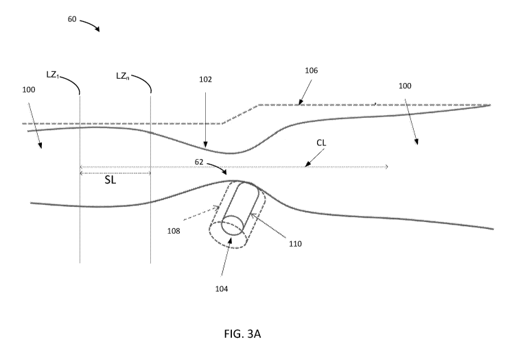
parameters using blood vessel data. A representation of the blood vessel is
generated and
displayed via a user interface. Stent deployment can be planned such that the
amount of
blood flow restored from stenting relative to an unstented vessel increases
one or more
1
CA 03037912 2019-03-21
WO 2018/064336
PCT/US2017/054017
metrics. An end user can specify one or more stent lengths, including a range
of stent lengths.
In turn, diagnostic tools can generate candidate virtual stents having lengths
within the
specified range suitable for placement relative to a vessel representation.
Blood vessel
distance values such as blood vessel diameter, radius, area values, chord
values, or other
cross-sectional, etc. its length are used to identify stent landing zones.
These tools can use or
supplement angiography data and/or be co-registered therewith. Optical
imaging, ultrasound,
angiography or other imaging modalities are used to generate the blood vessel
data.
[0007] In one embodiment, the disclosure relates to assessing a blood vessel
using a Virtual
Fractional Flow Reserve or Virtual Flow Reserve computational flow model. In
either case,
these can be referred to as VFR. As part of that assessment, the computer-
implemented
methods facilitate developing stent plan using virtual stenting, based on
predicted flow
recovery via a cardiovascular system parameter such as for example, VFR. Any
suitable
cardiovascular system parameter that changes as a result of stent deployment
can also be used
as a basis for scoring one or more virtual stents. In one embodiment, the
systems and
methods are designed to emphasize stent length relative to selection process
such that a
shorter stent is selected while simultaneously achieving a target flow
restoration level such as
a maximum flow restoration or otherwise increased flow restoration. In one
embodiment, a
representation of a blood vessel segment is generated based upon blood vessel
data such as
imaging data, which can include intravascular data or angiograhy or tomography
data. In one
embodiment, blood vessel data is obtained with during a pullback of a data
collection probe
through the actual corresponding vessel segment in a patient.
[0008] In part, the disclosure relates to a method of planning deployment of
one or more
intravascular stents. The method includes storing, in an electronic memory
device, blood
vessel data collected with regard to a candidate blood vessel for stent
deployment;
calculating, using a subsystem of an blood vessel data collection system, a
set of lumen
distance-based values from the blood vessel data, the subsystem in electronic
computing with
the electronic memory device; identifying a set of local maxima from the set
of lumen
distance-based values, wherein the local maxima are correlated with potential
stent landing
zones; determining one or more frames in the blood vessel data corresponding
to local
maxima; determining a set of candidate stent landing zones by identifying all
combinations of
pairs of frames disposed at boundary of a search window, wherein a size of
search window is
a length of one or more stents; and generating, for each pair of candidate
landing zones, a
2
CA 03037912 2019-03-21
WO 2018/064336
PCT/US2017/054017
stent effectiveness score (SES) that results from placement of a virtual stent
of a given
distance and length at each pair of candidate landing zones; ordering the
stent effectiveness
scores; and identifying one or more virtual stents, defined by landing zones
determined based
on a ranked order of the stent effectiveness scores.
[0009] The method may further include displaying the one or more virtual
stents relative to a
representation of a segment of the blood vessel. The lumen distance-based
values may be
selected from a group consisting of a lumen area, a lumen radius, a lumen
diameter, a lumen
chord, and a distance that is measured from a point on a boundary of a lumen.
The set of
lumen distance-based values may include a lumen area curve. The set of lumen
distance-
based values may include a set of lumen area values corresponding to cross-
sections of the
blood vessel. The method may further include generating a representation of a
stent having a
stent length and displaying the representation of the stent disposed at a
first landing zone and
a second landing zone, wherein the first and the second landing zone
correspond to the stent
effectiveness score.
[0010] Generating the SES may include one or more of calculating a first
virtual fractional
flow reserve (VFR) for the vessel prior to placing the stent; calculating a
second Virtual
Fractional Reserve for the vessel subsequent to placing the stent; subtracting
a first VFR from
second VFR to obtain a change in VFR in response to stent placement; and
dividing the
change in VFR by the length of the stent.
[0011] The method may further include adjusting the SES with one or more
weighting
factors. The one or more weighting factors may include one or more of: quality
of landing
zone; total lumen area of all branches covered by the stent; amount of
tapering of blood
vessel; stent limits based on physician preference; and restrictions based on
artery type. The
method may further include selecting the SES with a predicted VFR above or
equal to an end
user set target VFR. The method may further include receiving inputs from an
end user
regarding stent parameter preferences. The method may further include
generating a
predicted VFR in response to a user selected stent for placement relative to a
representation
of the blood vessel. The method may further include generating the blood
vessel data using
angiography or intravascular imaging.
[0012] In part, the disclosure relates to a system for automated stent
planning. The system
may include a diagnostic system to obtain data from a vessel of interest, the
diagnostic
3
CA 03037912 2019-03-21
WO 2018/064336
PCT/US2017/054017
system may include an electronic memory device; and a processor in
communication with the
electronic memory device, wherein the memory comprises instructions executable
by the
processor to cause the processor to: compute, using the processor, a set of
lumen distance-
based values from intravascular data generated using an intravascular probe
pulled back
through the blood vessel, the subsystem in electronic computing with the
electronic memory
device; identify a set of local maxima from the set of lumen distance-based
values, wherein
one or more local maxima are correlated with potential stent landing zones;
determine one or
more frames in the intravascular data that correspond to one or more of the
local maxima; and
determine a set of candidate stent landing zones by identifying one or more
frames disposed
at a boundary of a search window, wherein a size of search window is a length
of one or more
stents.
[0013] The lumen distance-based values may be selected from a group consisting
of a lumen
area, a lumen radius, a lumen diameter, a lumen chord, and a distance that is
measured from a
point on a boundary of a lumen. The system may further include instructions
executable by
the processor to cause the processor to: generate, for each pair of candidate
landing zones, a
stent effectiveness score (SES) that results from placement of a virtual stent
of a given
distance and length at each pair of candidate landing zones; rank the stent
effectiveness
scores; and identifying one or more virtual stents, defined by landing zones
determined based
on ranking of the stent effectiveness scores. In one embodiment, the one or
more virtual
stents are displayed relative to a representation of a segment of the blood
vessel.
[0014] The system may further include instructions executable by the processor
to cause the
processor to: generate a representation of a stent having a stent length and
displaying the
representation of the stent disposed at a first landing zone and a second
landing zone, wherein
the first and the second landing zone correspond to the stent effectiveness
score.
[0015] The system may further include instructions executable by the processor
to cause the
processor to: adjust the SES with one or more weighting factors. The one or
more weighting
factors may include one or more of: the quality of landing zone; total lumen
area of all
branches covered by the stent; amount of tapering of blood vessel; stent
limits based on
physician preference; and restrictions based on artery type. The system may
further include
instructions executable by the processor to cause the processor to: morph a
representation of a
vessel using a stent representation to compute a change in an intravascular
parameter suitable
for determining the SES.
4
CA 03037912 2019-03-21
WO 2018/064336
PCT/US2017/054017
[0016] In part, the disclosure relates to a method of planning deployment of
one or more
intravascular stents. The method includes storing, in an electronic memory
device, blood
vessel data of a blood vessel generated using an intravascular probe pulled
back through the
blood vessel; identifying candidate sent landing zones in blood vessel data;
determining a set
of possible landing zone pairs; scoring
virtual stent landing zones based on changes to
one or more vascular system parameters, wherein the changes are between
stented and
unstented state of blood vessel; ranking and selecting score and associated
landing zones; and
displaying landing zones for virtual stent having selected score.
[0017] Software embodiments can include programs, processor instructions,
firmware,
resident software, micro-code, pseudo code, flow charts steps, etc. Hardware
and software
may be combined or connected such as through a communication channel, memory,
wireless
communications and can be generally described as a "circuit," "module" or
"system."
[0018] The disclosure also relates to computer program product embodied in any
tangible
medium of expression having computer-usable program code embodied in the
medium. The
described embodiments may be provided as a computer program product, or
software, that
may include a machine-readable medium having stored thereon instructions,
which may be
used to program a computer system (or other computing or other electronic
device(s)) to
perform a process according to embodiments. A machine-readable medium includes
any
mechanism for storing or transmitting information in a form (e.g., software,
processing
application) readable by a machine (e.g., a computer). A machine-readable
medium may be a
machine-readable storage medium, or a machine-readable signal medium.
[0019] Computer program code for carrying out operations of the embodiments
may be
written in any combination of one or more programming languages, including an
obj ect-
oriented programming language such as Java, Python, C++ or the like and
conventional
procedural programming languages, such as the "C" programming language or
similar
programming languages. The program code may execute entirely on a user's
computer,
partly on the user's computer, as a stand-alone software package, partly on
the user's
computer and partly on a remote computer or entirely on the remote computer or
server.
Matlab and similar software can also be used to implement certain rankings and
plots used
herein.
[0020] Although, the invention relates to different aspects and embodiments,
it is understood
CA 03037912 2019-03-21
WO 2018/064336
PCT/US2017/054017
that the different aspects and embodiments disclosed herein can be integrated
together as a
whole or in part, as appropriate. Thus, each embodiment disclosed herein can
be incorporated
in each of the aspects to varying degrees as appropriate for a given
implementation. Further,
the systems, methods, steps, components, and parts of the foregoing can be
used for medical
applications and other applications for diagnostic purposes and stent
development and
analysis.
[0021] In one embodiment, the method is implemented using a cluster-based
method. For
example, a set of candidate landing zones is grouped based on one or more
criteria.
[0022] Other features and advantages of the disclosed embodiments will be
apparent from the
following description and accompanying drawings.
BRIEF DESCRIPTION OF THE DRAWINGS
[0023] The figures are not necessarily to scale, emphasis instead generally
being placed upon
illustrative principles. The figures are to be considered illustrative in all
aspects and are not
intended to limit the invention, the scope of which is defined only by the
claims.
[0024] Fig. 1 is a schematic diagram of an intravascular diagnostic / data
collection system
constructed in accordance with an illustrative embodiment the disclosure.
[0025] Figs. 2A, 2B and 2C are flow diagrams of stent planning methods that
use blood
vessel data from in vivo data collection during a pullback in accordance with
an illustrative
embodiment the disclosure.
[0026] Figs. 3A and 3B are schematic representation of blood vessels showing
stent landing
zone and flow restoration features in accordance with an illustrative
embodiment the
disclosure
[0027] Fig. 4A is a graph displaying frame position plotted against mean lumen
diameter for
a region of coronary artery imaged using data from a pullback in order to show
points
corresponding to local maxima of vessel diameter in accordance with an
illustrative
embodiment the disclosure.
[0028] Fig. 4B is a plot of virtual / hypothetical stent candidates (VSC)
plotted versus stent
effectiveness score (SES) values in accordance with an illustrative embodiment
the
disclosure.
6
CA 03037912 2019-03-21
WO 2018/064336
PCT/US2017/054017
[0029] Fig. 5A is an embodiment of a user interface display of a stent
planning / placement
system with a VSC shown relative the landing zone frames in accordance with an
illustrative
embodiment of the disclosure.
[0030] Fig. 5B is another view of the user interface of Fig. 5A in accordance
with an
illustrative embodiment of the disclosure.
[0031] Fig. 6 depicts a longitudinal view of a blood vessel representation
generated using
intravascular in vivo data that shows landing zones and areas of the vessel
wall that are
obstructing flow and candidates for displacement by stent deployment at the
landing zones
shown.
[0032] Fig. 7 depicts a plot generated as part of a cluster analysis to
identify three clusters as
shown in a plot of a parameter that changes post stenting with a virtual stent
and the ratio of
stent length to pullback length according to an illustrative embodiment of the
invention.
[0033] Figs. 8A-8E depict additional user interface views showing blood vessel
representations including longitudinal representation of stenosis of cluster 1
of Fig. 7
according to an illustrative embodiment of the invention.
[0034] Fig. 8F is a lumen profile view correspondign to a vessel
representation showing the
overlapping regions of cluster 1 from Fig. 7 and Figs. 8A-8E.
[0035] Fig. 8G depicts additional user interface views showing blood vessel
representations
including longitudinal representation of stenosis of cluster 2 of Fig. 7
according to an
illustrative embodiment of the invention.
[0036] Fig. 9 is a lumen profile view correspondign to a vessel representation
showing the
overlapping regions of cluster 2 from Fig. 7 and Fig. 8G according to an
illustrative
embodiment of the invention.
[0037] Fig. 10 depicts additional user interface views showing blood vessel
representations
including longitudinal representation of stenosis of cluster 3 of Fig. 7
according to an
illustrative embodiment of the invention.
[0038] Fig. 11 is a lumen profile view correspondign to a vessel
representation showing the
overlapping regions of cluster 3 from Fig. 7 and Fig 10 according to an
illustrative
embodiment of the invention.
[0039] Figs. 12A-12C depict additional vessel representation in the form of
profile views of
7
CA 03037912 2019-03-21
WO 2018/064336
PCT/US2017/054017
three lesions suitable for performing a clustering analysis to determine stent
deployment
options according to an illustrative embodiment of the invention.
DETAILED DESCRIPTION
[0040] In part, the disclosure relates to systems and methods for stent
planning. The systems
and methods described herein are implemented using blood vessel data obtained
using a
pullback of a data collection device such as an imaging device through an
artery. The data
collection device is typically an intravascular probe such as an optical
coherence tomography
(OCT) or intravascular ultrasound (IVUS) probe. The intravascular probe is
used in
conjunction with a data collection / diagnostic system such as an OCT or IVUS
system. The
system includes one or more computing devices that access the blood vessel
data such as
intravascular data stored in one or more electronic memory devices.
[0041] In one embodiment, the diagnostic system is used with the intravascular
probe can
access image data generated using data collected by the probe as it moves
through the artery.
This image data can be presented using various graphical user interfaces. The
diagnostic
system can provide various workflows and options to facilitate the process of
stent planning
relative to the artery imaged during such a pullback. Additionally, the
disclosure relates to
computer-implemented methods by which a stent effectiveness score (SES) or
other metrics
can be generated or used to perform stent planning. In one implementation, a
score or other
metric is assigned to a stent or a stent pair based upon the stent selection
and the positions of
each stent in the artery. That is, from a set of candidate stents or groups of
stents, each set or
group is scored or ranked relative to a criteria or score that is reflexive of
how the selection
and placement of the stent(s) affects a given vascular system parameter or
other parameter.
These scores can be tied to various vascular system parameters. In general,
the scores used to
select a candidate stent are referred to herein a stent effectiveness score
(SES).
[0042] For example, in one embodiment, the SES is designed to account for or
track the flow
improvement due to one or more of the location of a stent, the size of that
stent and the length
of the stent. This can be estimated using changes in a parameter as a result
of a given
candidate virtual stent. In one embodiment, the parameter used for estimating
flow changes
is Virtual Flow Reserve. Accordingly, in one embodiment, SES = AVFR/(Stent
Length)
wherein AVFR is the improvement in the VFR value due the placement of that
stent. In one
embodiment, stents that are shorter and result in an improvement in VFR will
have higher
8
CA 03037912 2019-03-21
WO 2018/064336
PCT/US2017/054017
SES values. In this way, SES is designed to reflect the benefit of using
shorter stents.
[0043] In general, deployment of shorter stents can result in less metal or
other material
being introduced in the artery. Using smaller stents can result in less trauma
given the
torturous nature of the arteries and their movement over time such as during
various activities
by a recipient of the stent. One or more shorter stents is sometimes desirable
because they
can be positioned to follow the bends of an artery rather one long stent which
may apply
stress to the artery when the artery bends or moves.
[0044] In one embodiment, the one or more cardiovascular or vascular system
parameters
suitable for generating a SES by which landing zones and the associated
virtual can include
without limitation a Virtual Flow Reserve (VFR) values, flow velocity, a
pressure value, a
maximum flow, a minimum flow one or more fractional flow reserve (FFR) values,
coronary
flow reserve (CFR) values, coronary flow velocity reserve (CFVR) values,
instantaneous
flow reserve (IFR) values, one or more index of myocardial resistance (IMR)
values and a
vascular resistance value, a combination of the foregoing, a weighted average
of one or more
of the foregoing and another value, and values derived from the foregoing. In
one
embodiment, virtual flow reserve can also refer to virtual fractional flow
reserve (VFR). In
general, a VFR value can be determined by using an intravascular imaging probe
to generate
frames of imaging data that segment the artery through a pullback.
[0045] In turn, this imagining data and lumen areas and diameters facilitates
a volume-based
analysis. Further, by using angiography and other parallel sources of data and
coupling them,
fluid dynamics, and the frames of imaging data vascular system parameters such
as VFR can
be used to obtain correlation similar to or better than FFR. These parameters
can be used
with virtual stents, landing zones, clustering-based methods and others
methods as described
herein to perform stenting planning and other diagnostic and analytic methods.
[0046] In one embodiment, the SES for each stent candidate that resulted in a
post-stent
predicted VFR of greater than about 0.80 or about 0.85 is ranked. These values
have been
determined from empirical studies as treatment thresholds. In one embodiment,
VFR or FFR
values range from about 0.7 to about 0.8 are ranking for virtual stent
selection given the
beneficial expected increase in flow post-stenting. These SES scores are
sorted in descending
order. The stent candidate with the largest SES from this sorted list can be
selected by the
system and displayed as a default stent selection for use by an end user. The
virtual stent
9
CA 03037912 2019-03-21
WO 2018/064336
PCT/US2017/054017
with such an SES score can also be identified to the end user as one option to
consider as part
of the stent planning process.
[0047] To inform and facilitate understanding of the operation of some aspects
of the
software and methods described herein, it is useful to consider an artery that
has a narrowing
in the middle, a stenosis, that effectively acts as a bottleneck. An exemplary
bottleneck 62,
such as from a stenotic lesion or other vessel obstruction, can be seen in
Fig. 3A which is
discussed in more detail below. Blood flow is reduced at the bottleneck or
point of stenosis
while proximal and distal areas downstream from the have larger diameters and
thus larger
cross-sectional areas relative to the contours of the walls of the blood
vessel.
[0048] Thus, along the blood vessel as measured by the imaging probe during
its pullback
through the vessel, there are cross-sections of the blood vessel which have
diameters of a
certain length and associated cross-sectional areas of a certain size such
that the diameters
and areas are maximized relative to other local cross-sections and lumen
diameters in their
vicinity. Lumen diameters and lumen cross-sectional areas can effectively be
treated
interchangeably herein because but for a scaling factor and some changes to
the appearance
of curves plotting these two parameters, a local maximum for a lumen diameter
will match up
with a local maximum for a lumen area (and vice versa). Other lumen distance
measures can
be used without limitation. With this example, it is useful to consider an
exemplary planning
system.
[0049] Referring to Fig. 1, a stent planning system for suggesting stent
placement options
and implemetnations of other embodiments includes an intravascular diagnostic
system / data
collection system 10 that in turn includes an intravascular probe 7. The probe
7 in various
embodiments may include other imaging modalities such as, for example, OCT,
intravascular
ultrasound (IVUS), and others. The probe 7 is in optical communication with an
intravascular diagnostic system / data collection system 10. The OCT optical
system or
subsystem 31 that connects to probe 7 via an optical fiber 15 includes a light
source such as a
laser, an interferometer having a sample arm and a reference arm, various
optical paths, a
clock generator, photodiodes, and other OCT system components.
[0050] The system 10 further includes one or more diagnostic software tools or
modules 12
relating to stent planning. This software can be stored as a non-transitory
instruction on one
or more memory devices such as memory device 45 and executed by one or more
computing
CA 03037912 2019-03-21
WO 2018/064336
PCT/US2017/054017
devices such as computing device 40. The stent planning software tools can
include one or
more vessel profiles such as target profiles generated by a user, a comparator
or other
comparison software routine for comparing pre and post stent profiles or other
profiles. The
stent profile analysis software 12 can include an overlay method suitable to
superimpose the
image of a deployed stent relative to a target profile or to otherwise overlay
one or more pre
or post stent profiles. In general, the software 12 can process a set of
intravascular data and
carry out the various methods steps described herein such as those described
with regard to
Fig. 2A, Fig. 2B and Fig. 2C.
[0051] The software 12 is designed to operate upon intravascular data sets and
othe blood
vseel data from an intravascular probe or other detector or data source such
as an
angiography system. In one embodiment, blood vessel data can be recorded
during a
pullback procedure and stored in an electronic memory device. The software can
include
various modules or operative components to perform one or more of the
processes or
methods described herein. The stent planning software 12 can include without
limitation one
or more of the following software components or modules: Lumen Contour
Detection 12A;
Side Branch Detection 12B; Landing Zone Generation 12C; Virtual Stent Scoring
12D;
Virtual Stent Selection 12E; User Interface and Input Processing 12F; Virtual
Stent
Representation 12G; Indicia / Indicator Overlay 12H, Clustering Analysis for
Overlap Zones
121 and others as described herein with regard to different processes and
methods.
[0052] In one embodiment, software modules designed to operate upon
intravascular data to
characterize the tissue and identify regions of interest such as calcium
regions, taper regions,
lipid pools, and other tissue features can be used to lower a given SES if
placement of a
landing zone on one of these tissue types or a side branch location is
undesirable. The
software 12 can also compare Fractional Flow Reserve (FFR), Vascular
Resistance Ratio
(VRR), and other measured and calculated intravascular data collection
parameters. To the
extent such parameters change from a stented state to a non-stent state, such
parameters can
be used to generate one or more SESs.
[0053] In one embodiment, an OCT system 31 can be used. The system includes an
optical
receiver such as a balanced photodiode based system receives light returned by
the probe 7.
A computing device 40, such as a computer, a processor, an ASIC or other
device that is part
of the system 10 or is included as a separate subsystem in electrical or
optical communication
with the system 10 and receives electronic signals from the probe 7. The
computing device
11
CA 03037912 2019-03-21
WO 2018/064336
PCT/US2017/054017
40 in various embodiments includes local memory, buses and other components
suitable for
processing data and utilizing software 44, such as image data processing
configured for stent
visualization and stent malapposition detection. The stent deployment planning
tools 12 can
be part of or exchange data with software 44. These tools can be used to place
a virtual stent
in the lumen area that the probe 7 is disposed in relative to vessel wall.
Region 19 shows an
exemplary region of a segment of a pullback wherein one or more virtual stents
can be
deployed and displayed on a user interface.
[0054] As shown, in Fig. 1, a display 46 can also be part of the system 10 for
showing
information 47 such as cross-sectional and longitudinal views of a blood
vessel generated
using collected intravascular data. Once the intravascular data is obtained
with the probe 7
and stored in memory 45, it can be processed to generate and display
information 47 such as
a cross-sectional, a longitudinal, and/or a three-dimensional view of the
blood vessel along
the length of the pullback region or a subset thereof These views can be
depicted as part of a
user interface as shown and described below and in subsequent figures. The
images of the
blood vessel generated using the distances measurements obtained from the
system 10
provide information about the blood vessel including lumen contours, vessel
diameters,
vessel cross-sectional areas, landing zones, and a virtual stent bounded by
the landing zones
when processed using the tools and software modules described herein.
[0055] The methods and systems disclosed herewith provide diagnostic and
planning tools
for a user. For example, the methods and systems include tools such that
placement of virtual
stents in an artery can be performed automatically relative to image data from
a pullback.
Further, the automatic placements of such stents include processes, user
interface, and related
software-based features to display such stents at optimal locations and with
the size of a
suitable stent identified for an end user.
[0056] The disclosure includes various implementations of stent planning
software to place a
stent at an optimal location or otherwise at a location that optimizes certain
parameters. In
one embodiment, the parameters optimized to facilitate stent planning include
the amount of
flow, which can be achieved by deploying a stent of a particular length. The
proximal and
distal landing zone locations for the stent and the size of the stent are
provided to an end user.
These are determined by optimizing the improvement in flow that can be
achieved using a set
of possible stents and stent deployment locations.
12
CA 03037912 2019-03-21
WO 2018/064336
PCT/US2017/054017
[0057] As one exemplary approach to evaluating flow restoration as a result of
stent
deployment, the methods described in U.S. Patent Application No. 14/115,527
entitled
"METHOD AND APPARATUS FOR AUTOMATED DETERMINATION OF A LUMEN
CONTOUR OF A STENTED BLOOD VESSEL," the contents of which are incorporated by
reference herein in their entirety, can be used. Other approaches can be used,
including as
otherwise as recited herein. To understand some aspects relative to flow
changes and
behaviors in an artery, it is informative to consider the features shown in
Figs. 3A and 3B
which show a stenosis and various features relating to the selection and
position of virtual
stents based on identified landing zones and stent length(s).
[0058] The disclosure also provides computer implemented methods for
calculating the
degree of branch obstruction. In turn, obstructed or narrowed areas that are
candidates for
stent deployment can be evaluated in their obstructed state and then compared
to an
unobstructed state as a result of the lumen diameters and associated lumen
areas being
morphed through the dilation of an area of a vessel from positioning a
candidate virtual stent
between target landing zones. Several methods can be used to calculate branch
obstruction
due to the presence of pathology (e.g., stenosis) or medical intervention
(e.g., jailing of side
branches).
[0059] In an embodiment, a reference vessel diameter method is used to assess
blood vessel
obstruction. Fig. 3A shows a representation of a vessel 60 having a main
vessel 100 having a
stenosis 102. A side branch 104 also is shown. Using the virtual stent
candidate scoring
various landing zones for a stent are evaluated. Exemplary landing zones for a
stent of stent
length SL is shown on the left side of Fig. 3A. A center line CL of the
representation of the
vessel 60 is also shown.
[0060] Typically, as shown in a zoomed in view 70 of Fig. 3B of the stenosis
102, one
virtual stent 111 can be deployed relative to the stenosis 102 to expand the
lumen of the
blood vessel. The virtual stent contacts the blood vessel at points Z1 and Z2
on the right side
of the figure and points Z4 and Z3 on the left side of the figure. If these
two pairs of points
are considered as being disposed along a frame, one frame on the left Fl and
one frame on
the right F2, these frame are examples of those that would be selected as a
result of
containing a local maximum. The dotted vertical line 115 is included to show
that, instead of
a single stent 111, two stents can be deployed and select as vertical stents
with line 115 being
shown as a diving reference line for stents 111a, 111b.
13
CA 03037912 2019-03-21
WO 2018/064336
PCT/US2017/054017
[0061] As part of the process of scoring and selecting virtual stents as
candidates for
deploying in an artery, multiple landing zones are considered for the blood
vessel. Thus, for
stent 111 shown, it is informative to consider multiple versions of such as
stent having the
same length SL but shifted to the left and right of frames Fl and F2. These
sets of possible
landing zones and thus the virtual stents bounded by them can form a cluster
that spans a
particular subset or region of the blood vessel. Overlapping landing zones can
be used to
selected preferred landing zones for stent deployment.
[0062] A cluster based analysis to identify and select regions of candidate
stent overlap can
be useful because such regions of overlap can be identified as regions in
which some level of
stenting is required to satisfy the constraints of the stent planning software
given the presence
of flow obstructing stenosis, lesions, bottlenecks, etc. Fig. 7 shows an
exemplary plot of
clusters Cl, C2, and C3 relative to post stent VFR and the ration of the stent
length to length
of pullback through the blood vessel. Each cluster Cl, C2, and C3 corresponds
to a stenotic
lesion as shown in the longitudinal views of Figs. 8A-11. Figs. 12A, 12B and
12C also show
profile views generated with blood vessel data for three lesions that can be
used to perform a
clustering analysis. As shown, in the foregoing figures the clustsers and
lesions map to and
correlate with each other.
[0063] In general, a clustering analysis is used to guide the stent placement
by identifying the
critical sections that need to be stented first. A plot of the VFRpost vs
length of stent
normalized to the pullback length for each candidate stent shows distinct
clusters as shown in
Fig. 7. There are three clusters that can be seen and the number of clusters
correlate with the
number of lesions in the pullback. Based on the cluster analysis the following
stenting guide
is derived, a default stent is shown at the critical stent section as shown in
Fig. 12B and 12C
to achieve the increase in VFR. Although VFR is referenced, the clustering
analysis applies
to any parameter described herein. Figs. 8A-11 depict additional
representations of a blood
vessel with lumen 303 and various landing zone positions LZ1 and LZ2. These
figures show
regions of overlap for which stent placement for different landing zones
advantageously
changes VFR. These overlapping regions can be analyzed using a cluster-based
approach as
discussed herein. The position of the landing zone selected by an end user or
determined
using methods and systems disclosed herein change the lumen profile and
expands regions of
stenosis 305.
14
CA 03037912 2019-03-21
WO 2018/064336
PCT/US2017/054017
[0064] Further, Figs. 8A-8E show vessel representations in the form of a
vesssel or lumen
profile representation or view. Figs. 8A-8E correspond to cluster 1 in Fig. 7.
The overlap
region for cluster 1 is shown in Fig. 8F. In Fig. 8F, profile view / vessel
representation 400
shows the overlap region is 18 mm in length and is in between the two vertical
lines that
bound a region where stenting should occur. The vertical line pairs in each of
Fig 8A-8E
correspond to the five points shown for cluster 1 in Fig. 7. Fig. 8G shows
three profile views
that correspond to cluster 2 in Fig. 7. The three points in cluster 2 map to
the three regions
demarked as between each of the three landing zone pairs LZ1, LZ2 of Fig. 8G.
Fig. 9 shows
the overlapping region in cluster 2, which is 30 mm in length. In Fig. 7 the
overlapping
region can be shown by circling a point in the cluster as shown in one
embodiment. Fig. 10
shows two profile views460 that correspond to cluster 3 in Fig. 7. Fig. 11 is
profile view 470
shows the overlapping region in cluster 3, which is 47 mm in length. Areas of
overlap based
on clustering are recommended for stent landing zone positions in one
embodiment.
[0065] FIG. 2C describes the method steps of an exemplary clustering analysis
approach. In
general, the 12A, 12B and 12C. Based on the cluster analysis a stenting guide
is derived. For
example, landing zones or a default stent can be shown at the critical stent
section in the user
interface. Regions of overlap for multiple clusters can be used to generate
this section and its
landing zone endpoints. This is the stent that the software places
automatically when stent
planning is enabled, in one embodiment, as shown in FIG. 12B. The critical
section
corresponds to the intersection or overlapping region that is common to all
three clusters.
Using the cluster analysis an area where the end user should consider
evaluating stent
deployment is shown.
[0066] Fig. 12A shows the clusters near side branches SB and lesion Li, L2,
and L3. The
lumen 303 is in the middle of the image. The three lesions are in tandem from
left to right
and are canidates for a cluster analysis. In Fig. 12B, the critical landing
zones, LZC1 and
LZC2, based on cluster intersection / overlap, these landing zones are good
candidates for
stent deployment. With regard to each cluster, C3 gives biggest incremental
improvement for
stenting. The critical stenting zone does appear to be identify by the
interrelationship of the
clusters. Region 305 shows stenosis or lesion tissue that should be expanded
with a stent to
increase flow. Typically, the system would indicate not to ignore lesion C2
because overlap
from cluster occurs there. In FIG. 12B, a vertical dotted line 495 and an
associated bracket
shows a section suitable for stent placement to change the VFR to 0.85 in
response to this
CA 03037912 2019-03-21
WO 2018/064336
PCT/US2017/054017
section being stented. If only this section is stent it is possible to
increase the VFR from 0.70
to a predicted value of 0.84.
[0067] [00011In general, a clustering analysis is used to guide the stent
placement by
identifying the critical sections that need to be stented first. A plot of the
VFRpost vs Length
of stent normalized to the pullback length for each candidate stent shows
distinct clusters as
shown in Fig. 7. There are three clusters that can be seen and the number of
clusters correlate
with the number of lesions in the pullback. Based on the cluster analysis the
following
stenting guide is derived, a default stent is shown at the critical stent
section as shown in Fig.
12B and 12C to achieve the increase in VFR. Although VFR is referenced, the
clustering
analysis applies to any parameter described herein or otherwise suitable for
use with blood
vessel imaging and stent deployment such as FFR.
[0068] Referring back to FIG. 3A, a reference profile can be created for the
main vessel 106
and/or a reference profile 108 can be created. Additional details for
reference profiles are
described in U.S. Patent Application No. 14/115,527 entitled "METHOD AND
APPARATUS FOR AUTOMATED DETERMINATION OF A LUMEN CONTOUR OF A
STENTED BLOOD VESSEL." Reference profiles are also shown that vary for
different
depictions of an artery with VFRp (VFR post morphing of lumen and vessel after
application
of a virtual stent) and VFR (VFR determined before deployment of identified
and SES scored
virtual stent). See Figs. 8A-8B, for example. Using the reference profile
(dotted line) 108
also referred to as RP, an estimated blood vessel diameter can be calculated
by using distal
and proximal reference profile diameters. The proximal and distal reference
can be analyzed
using a power law relationship.
In one embodiment, the power law is given by the expression:
D(i) = DE(i + 1) ¨ DE(i) (Eqn. 1)
where D(i + 1) is the proximal reference profile diameter and D(i) is the
distal reference
profile diameter; where Db (0 is the estimated true blood vessel diameter; and
E is a power-
law scaling exponent that has a value between 2.0 and 3.0 as determined
empirically.
[0069] The difference between the estimated blood vessel diameter and the
actual blood
vessel diameter detected by OCT imaging provides the level of blood vessel
obstruction. In
one embodiment, the level of blood vessel obstruction is given by the
expression:
16
CA 03037912 2019-03-21
WO 2018/064336
PCT/US2017/054017
D obstruction () = Db DocT(i) (Eqn.
2)
where Db (0 is the estimated true blood vessel diameter, and D obstruction
Db (0 ¨
D OCT (0is the actual blood vessel diameter measured by OCT.
[0070] In an embodiment, a max diameter frames method is used to assess side
branch
obstruction. Instead of using a reference profile, the branch diameter is
estimated using the
maximum diameter in the main vessel segment distal and proximal to the current
branch.
[0071] In an embodiment, a flow method is used to assess blood flow in an
artery. For
example, a flow method can be used to evaluate flow in arterty that has been
altered due to a
stenosis, under inflated stent, narrowing or other obstruction in the artery.
Using Virtual
Flow Reserve (VFR) the flow going into each side branch can be estimated. The
difference in
flow down a given side branch due to the difference in OCT based branch
diameter
FlowocT(i) and the true branch diameter Flowb(i) is an additional indication
of the effect on
flow due to the obstructed side branch. The true branch diameter can be
calculated using one
of the methods described above by either using the reference vessel profile or
the max
diameter frame in the distal and proximal segments. The flow method can be
given as the
following expression:
FlOWobstruction FlOWb ¨ FlOW0cT (i) (Eqn. 3)
[0072] In various embodiments, a stenosis or other obstruction is represented
on a user
display using visual indicia, such as color-coding. The indicia can be coded
to confer the
level of obstruction. These indicia can also be set based upon user input via
a user interface.
[0073] In complex lesions, the best optimal location and size of the stent is
not always
obvious. Several factors like flow, branching pattern, vessel diameter, etc.
need to be taken
into account. The systems and methods described herein that use diagnostic
intravascular
imaging systems and algorithms designed to operate on such system outputs to
determine the
optimum location and size of the stent. An end user, such as a cardiologist,
researcher or
technician can use the algorithm generated virtual stent as a guide to place
the stent. There
can be instances where the clinician or other end user cannot predict which
size stent and at
what location would give the best outcome for the patient in terms of improved
blood flow
and reduced restenosis. In one embodiment, the systems and methods of the
disclosure are
implemented using computer algorithms to predict a desirable location for
placing the stent
that maximizes desirable quantities such as blood flow for the shortest
possible stent length.
17
CA 03037912 2019-03-21
WO 2018/064336
PCT/US2017/054017
[0074] As part of this process, in one embodiment, the method operates on the
intravascular
data collected in vivo with a data collection probe to identify all possible
frames that are
candidate landing zones for a stent. All combination pairs of these landing
zones are
computed, with each pair corresponding to a virtual stent's distal and
proximal landing zone.
An optimization step is performed where a ranking or score is provided to each
virtual stent
based on the improvement in flow and the length of the stent. This provides a
general
overview of one implementation of a stent planning process.
[0075] In one embodiment, as part of stent deployment planning, the candidate
virtual stent
(also referred to as a stent representation) is one that maximizes flow per
length of stent and
is in the optimal landing zone. In general, the "best" or otherwise highly
ranked candidate
virtual stents are those that maximize, improve upon or otherwise change one
or more
intravascular parameters in a desirable way.
[0076] In one embodiment, as shown in Fig. 2A, a method of stent planning is
depicted. In
general, identifying local maximum based on area or diameter (as a correlated
factor with
area), results in the selection of areas for landing zones such that there
will not be tearing,
tenting or any sharp discontinuities as a result of the stent width, the stent
expansion, and the
regions of the vessel that acts as the landing zone. Accordingly, large
diameters regions in
the artery are the candidate landing zones the methods described herein are
designed to target
while regions of the artery with side branches, high taper, narrowed regions,
and others are
avoided. This consideration informs the steps of the method of FIG. 2A and
others described
herein. In one embodiment, the method includes storing, in an electronic
memory device,
intravascular data of a blood vessel generated using an intravascular probe
pulled back
through the blood vessel.
[0077] As shown in FIG. 2A, the method includes identifying candidate sent
landing zones in
intravascular data (Step Al). The method also includes determining a set of
possible landing
zone pairs (Step A2). Scoring virtual stent landing zones based on changes to
one or more
vascular system parameters (Step A3) is another step. Optionally, it is
possible to modify the
score using weighting factors such as described herein (Step A4). In one
embodiment, the
changes are between stented and unstented state of a blood vessel such as VFR
pre- and post-
virtual stent deployment. The method can include ranking and selecting a SES
(Step A5) and
the associated landing zones with selected score. Also, the method can include
displaying
landing zones for a virtual stent having a selected score (Step A6).
18
CA 03037912 2019-03-21
WO 2018/064336
PCT/US2017/054017
[0078] It is worth noting that the disclosure is not limited to maximal values
and all of the
values described herein can be also evaluated in terms of a set threshold or
comparison to a
baseline to determine some degree of improvement in the parameter as a result
of the position
and length of one or more stents. In one embodiment, as part of one of various
possible work
flow scenarios for an end user, the virtual stent is presented to the end user
as a default virtual
stent as part of the graphical user interface of the intravascular data
collection system.
[0079] In one embodiment, the systems and methods disclosed herein automate
the decision
process of placing a stent at a location, having a proximal location and a
distal location, such
that the stent is deployed between the proximal location and the distal
location such that one
or more dimensions of the stent, such as length and diameter, are selected to
improve blood
flow. The improvement to blood flow can be within a range of values, an
optimal flow value,
a relative extremum flow value, or another flow value selected by an end user
via a user
interface or other input mechanism. In one embodiment, the algorithm searches
through all
possible combinations of stents to evaluate the best stent location and size.
[0080] In this way, the systems and methods described herein can identify
candidate stents
with a recommended size, length, and placement location that is likely to
result in a desirable
outcome for the patient in terms of the criteria selected for scoring the
candidate virtual stents
such as for example parameters that change after stent deploy to improve blood
flow and/or
otherwise reduced restenosis. The disclosure also incorporates by reference in
its entirety
U.S. patent publication 20110071404 "Lumen Morphology and Vascular Resistance
Measurements Data Collection Systems, Apparatus and Methods" filed on
September 22,
2010 which described identifying and displaying lumen contours as well
described methods
of automatically constructing a mean-diameter profile of a branched vessel via
automated
processing of intravascular images. The use of mean diameters and lumen areas
can be used
to identify local maxima and thus identify candidate landing zones as
described herein.
[0081] In brief overview, once the image of a portion of a coronary vessel of
interest has
been acquired and analyzed, the system calculates the optimal sizes and
locations for stent
placement. The term "locations" means the positions in the vessel at which the
ends of the
stent make contact with the vessel walls. These locations may be referred to
as landing zones
or sites.
[0082] In operation, the stent placement algorithm first identifies all
possible frames that are
19
CA 03037912 2019-03-21
WO 2018/064336
PCT/US2017/054017
candidates for placement locations or landing zones for a stent. Landing zones
for each end
of the stent are computed for all combination pairs of distal and proximal
locations in the
vessel, with each pair corresponding to a stent's distal and proximal landing
zone
respectively. An optimization step then may be performed to rank or score each
potential
stent placement pairs based on the calculated improvement in flow and the
total length of the
stent. In one embodiment, the desirable or optimal stent to deploy is one
which maximizes
flow per unit length of stent and is in the optimal landing zone. This
potential stent is
presented to the clinician or other end user as the default potential stent in
one embodiment.
These tools can be used with angiography to further enhance stent delivery.
[0083] In more detail and referring to Fig. 2B, another exemplary stent
planning or candidate
virtual stent placement method is shown. Initially, blood vessel data such as
imaging data,
distance measurements relative to blood vessel, intravasular data, angiography
data,
tomography data or othe data is generated that is suitable to generate a
representation of a
blood vessel for user review and display on a diagnostic system (Step 20). In
one
embodiment, side branch detection is first performed (Step 21) using such a
representation.
The method is then able to ignore the detected side branch locations to
determine lumen
diameters, lumen radii, lumen chords, lumen areas, or a representation thereof
such as a
lumen area curve (Step 22) using one or more methods such as those described
in U.S. Patent
Application No. 14/115,527 entitled "METHOD AND APPARATUS FOR AUTOMATED
DETERMINATION OF A LUMEN CONTOUR OF A STENTED BLOOD VESSEL." In
general, this step includes generating lumen-based distance measurements from
blood vessel
data and/or the vessel representation. (Step 22)
[0084] In general, a lumen area cuve or a lumen diameter curve is a
representation of lumen
areas or diameters generated based on a representation of blood vessel created
using data
from an intravascular pullback such as an OCT or IVUS representation of a
blood vessel.
The local maxima corresponding to areas of the blood vessel with a lumen that
is sufficiently
wide that it can be fit with a stent of a suitable thickness are identified.
This can be
performed using a curve or a table by which lumen areas along the length of
the vessel or
lumen diameters (which are directly correlated with lumen areas) are ranked,
searched, sorted
or otherwise evaluated and compared to identify local maximum values. The
method can
use a lumen area curve or other data sources to generate blood vessel data
such as
intravascular data. This data can come form other imaging modalities such as
angiography,
CA 03037912 2019-03-21
WO 2018/064336
PCT/US2017/054017
tomography and ultrasound. Local maxima (LM) can be determined from various
types of
blood vessel data such as intravascular data generated with an imaging probe
(Step 24).
[0085] The stent placement method determines the frames corresponding to local
maxima
(LM) in the curve or generally from blood vessel data (Step 26). The local
maxima (LM)
values correspond to a cross-section of the blood vessel having a lumen
diameter and thus a
lumen area that is larger relative to other cross-sections of the lumen within
a certain segment
of the blood vessel. As a result, the image frames, formed from a plurality of
scan lines, each
correspond to a polar slice of the blood vessel. The frames with LMs define a
set from which
candidate virtual stent landing zones (LZ) can be identified. In partial, by
using a selection
process that generates a search window defined by the lengths of possible
stents, such a
window can be positioned relative to candidate landing zones to identify
landing zone pairs
where a virtual stent can be displayed in a representation of the blood vessel
using a window
size that corresponds to the stent length.
[0086] Fig. 4A shows a plot 120 of mean diameter (y-axis) versus frame number
(x-axis) for
a set of blood vessel data. Each frame is a slice of the blood vessel or image
representation
thereof in one embodiment. The local maximums in the mean diameter are show as
dark
points along the curve. Side branch locations are also shown. This set of
local maxima
provides one representation of lumen area / lumen diameter data to identify
candidate landing
zones. Fig. 4B is plot 140 of virtual / hypothetical stent candidates (VSC)
plotted versus stent
effectiveness score (SES) values. As shown, by the series of points that slope
down to the
right, the virtual stent frames or landing zones are ranked with landing zone
145 being the
highest in rank order and possibly the preferred candidate as a location for
stent deployment.
All of the local maxima candidate frames shown in Fig. 4B are candidates for
stent
deployment. The selection of stent length further constrains these values to a
pair of frames
in one embodiment. In one embodiment, VSC are depicted as as hatched pattern
on a panel
or subscreen of a user interface as shown in Figs. 5A and 5B.
[0087] The stent lengths to be devalued can be specified by an end user via a
user interface
input. In one embodiment, the window is set as the shortest stent length
available from the
set of stent that the end user can use for a given procedure. In one
embodiment, the stent
length is about 8 mm. However, stent lengths can be set as a search window for
landing
zones without limitation. In addition, two stents can be used with the window
set based on
their combined length. The stent placement algorithm next generates a set or
list (Step 32 of
21
CA 03037912 2019-03-21
WO 2018/064336
PCT/US2017/054017
Fig. 2) of the local maxima.
[0088] The system next (Step 36) generates a list of all combinations of LM
pairs. Each pair
includes two possible stent landing zone locations, one for each end of the
stent. There is a
total of Nstentsl = (N) or "N taken 2 at a time" pairs of stent landing zone
location
2
candidates, where N is the number of local maxima. This binomial coefficient
representation
is used because there are n ways to choose 2 elements, disregarding their
order, from a set of
N elements. The binomial coefficient is the number of ways of picking
unordered outcomes
from possibilities, also known as a combination or combinatorial number. The
method uses
such an approach to pick frames as candidate landing zones (LZ) based on local
maximum of
lumen area / lumen diameter. This follow because a stent is advantageous
placed in a region
of the lumen where the ends of the stent fit with the lumen profile and avoid
a step or other
sharp discontinuity when deploying the stent.
[0089] For example, if there are three local maxima A, B, C, then Nstentsl =
(3) = 3 and the
2
three candidates are (NAB, NBC and NAC). Thus, the landing zone frame pairs
would be
pairs of frames A and B, pairs of frames B and C and pairs of frames A and C.
[0090] From these local maxima candidates a further combination is generated
(Step 40)
where Nstents2 = (Nstentsl). Again, because Nstentsl = 3 then Nstents2 = 3
which is every
2
possible combination of two stents in a given pullback. As discussed herein,
it may
sometimes be advantageous to deploy two shorter stents rather than one longer
stent. The
total stent length or the window used for searching for landing zones would be
the length of
each stent together.
[0091] For each stent landing zone combination, which defines one or more
virtual or
hypothetical stents for deployment in the blood vessel, the system next
generates (Step 44) a
stent effectiveness score (SES). The SES takes into account the flow
improvement as
estimated using the change in Virtual Flow Reserve that results from the
placement of the
stent of a given diameter and the length at a specific location in the vessel.
The stent
effectiveness score is defined as:
SES = AVFR/(Stent Length) = (VFRafter placement VFRbefore placement)/(Stent
Length)
where AVFR is the change in the VFR number that results from the placement of
that stent.
22
CA 03037912 2019-03-21
WO 2018/064336
PCT/US2017/054017
[0092] The denominator is designed such that stents that are short and provide
the maximum
improvement in VFR, will have higher SES values. That is, the shorter of two
stents
producing the same AVFR will have a higher SES because a shorter stent is
preferred over a
longer stent as discussed herein. In general, a shorter stent can more easily
track the contours
of an artery. Accordingly, two shorter stents can more closely follow the
contours of an
artery and bend. A longer stent, the length of two smaller stents cannot bend
in the same way
at a point of flexion. As a result, one aspect of the disclosure relates to
selecting multiple
shorter stents by assigning them a higher SES score in various embodiments.
[0093] The SES can be further modified by including additional weighting
factors. The
weighting factors can be a penalty factor that reduces a given SES value or an
additive factor
that increases a given SES for a particular stent deployment scenario or set
of criteria. The
additive or penalty factor can be used to generate terms weighted based on
some of the
factors outlined below and as otherwise described herein.
[0094] The quality of landing zone, which in various embodiments is determined
by tissue
characterization or by the difference between the normal vessel area and the
actual lumen
area in that region can be used as a factor. This can be facilitated by using
a calcium
detection software module or a tissue characterization software module.
[0095] The total lumen area of all branches that are covered by the stent can
be used as a
factor. If a small side branch is jailed, this may be a small negative factor,
but if all or a
majority of branches are jailed, this would result in a large negative factor
to reduce a given
SES as applicable. In this way, jailing of stents during stent deployment can
be avoided or at
least presented to an end user.
[0096] As part of the stent planning tools, an end user can set stent limits
based on user
preferences such as BRS, thickness, length, material, and other factors. These
inputs can be
used to adjust the SES weighting factors based on criteria relating to how
such user selections
affect the benefits of a particular landing zone.
[0097] The amount of tapering in artery can affect the SES for particular
types of stents. In
some embodiments, a tapered artery or a tapered region of an artery is not
suitable for use
with a BRS. As a result, the presence of a taper, such as detected by the
geometry of the
lumen contours can penalize or decrease the SES score for the use of such a
stent in an artery
having a tapered region or other geometric constraint ill-suited for deploying
a BRS. For
23
CA 03037912 2019-03-21
WO 2018/064336
PCT/US2017/054017
some BRS, the ability to expand the stent can be constrained such that using
it in the vicinity
of a vessel region with too much taper ¨ such as a steep cone-shaped region is
not desirable.
Thus, a landing zone frame with such a taper would have its SES reduced by a
negative
weighting factor if a BRS stent type was identified in the user interface.
Thus, the expansion
limit is on stent constrains used in certain locations with a significant
taper and is the basis
for SES reduction.
[0098] In addition, physiological constraints relating to the type, size,
thickness and other
factors by which a stent is selected for a given artery can be used as the
basis for an additive
weighting factor or a negative weighting factor when determining SES for a
given artery type
and landing zone scoring. Accordingly, the weight factor used for SES
computation can vary
based on artery type such as for example carotid artery, right coronary
artery, left coronary
artery, circumflex artery and the left anterior descending, and other arteries
as applicable.
[0099] After the SES is computed for each pair of local maxima, the placement
algorithm
orders (Step 48) the pairs and selects the best SES. The highest scoring stent
locations are
then displayed (Step 52) as the best corresponding stent location(s). The
details described
herein with regard to Fig 2B can also be used with regard to the other methods
and
processing steps described in Fig. 2A and otherwise.
[00100] In another embodiment, the user may set a target VFR (or other
parameter) or
minimum VFR (or other parameter) that the user would like to achieve and the
stent
placement algorithm searches for the stent location combination that provides
the highest
SES with a predicted VFR (or other parameter) above or equal to the physician
set target
VFR (or other parameter). Various VFR values and predicted or post-stenting
VFRp values
are depicted in the longitudinal representations of the blood vessel segments
shown herein.
Similarly, this same parameter target setting can be performed using the user
interface and
any of the cardiovascular parameters described herein.
[00101] Other parameters that the end user can set or that can be used in lieu
of or in
addition to VFR to assess based on landing zones and SES values include,
without limitation,
flow velocity, a pressure value, a maximum flow, a minimum flow, one or more
fractional
flow reserve (FFR) values, virtual fractional flow reserve values, coronary
flow reserve
(CFR) values, coronary flow velocity reserve (CFVR) values, instantaneous flow
reserve
(IFR) values, one or more index of myocardial resistance (IMR) values and a
vascular
24
CA 03037912 2019-03-21
WO 2018/064336
PCT/US2017/054017
resistance value, a combination of the foregoing, a weighted average of one or
more of the
foregoing and another value, and values derived from the foregoing
[00102] Figs. 5A and 5B depicts a typical user interface screens, 150, 152,
respectively of a
display that is connected to an intravascular diagnostic system such as that
described with
regard to Fig. 1. With respect to interface screens 150, 152, various other
user interface
components of the diagnostic systems and software-based tools UIA, UIB, UIC,
UID, and
UIE are shown. The user interface is used by an end user for stent planning
using the
systems and methods described herein. As part of the operation of the system,
one or more
user interface software modules are executed to display information to a user
regarding the
processed intravascular data. This display is composed of five r screens. The
first user
interface screen 160 (UIA) is a perspective view of an OCT image of a vessel
of interest.
The second user interface screen 164 (UIB) is an axial cross-sectional view of
a portion of the
vessel indicated by ring 166 in user interface screen 160. As shown in Fig.
5B, the VFR
without the VSC depicted is 0.7 and it increases to a predicted value fo VFRp
of 0.86 if the
VSC shown were depicted.
[00103] By moving the ring with the user interface, different cross-sections
may be shown
in user interface screen 164. User interface screen 168 (UID) is a stylized
longitudinal cross-
section of the vessel on user interface screen 160. User inteface screen (UIC)
shows details
of measured and/or determined values for the vessel representation in user
interface screen
168 (UID). A stent has been located on the longitudinal cross-section so that
the physician
can determine fit. The black vertical bands are the branches of the vessel.
User interface
screen four is an image of an actual longitudinal cross-section of the vessel
in user interface
screen 160. Line 176 on both screens 168 and 172 also corresponds to the
location of ring
166 on user interface screen 160. The VSC shown in interface screen 168 is
user adjustable
or determined based on determination of landing zones LZ1 and LZ2.
[00104] In one embodiment, an optimized search is performed that maximizes one
or more
variables that influence a stent deployment decision and stent placement.
In one
embodiment, such an optimized search-based approach treats each variable
and/or the weight
associated with such a variable as a dimension in a n-dimension space. In
turn, the peaks in
the resulting n- dimension space represent the stent that optimizes one or
more (or all) of the
variables specified.
CA 03037912 2019-03-21
WO 2018/064336
PCT/US2017/054017
[00105] In still another embodiment, a machine learning algorithm is trained
based upon
current physician practices for deploying stents. The training can be
implemented by
teaching the algorithm the weightings provided based upon one or more criteria
variables that
influence a stent deployment decision and stent placement. The algorithm
training can also
include different types of patient data and different types of arteries.
Accordingly, using the
trained feature set, the algorithm can predict a suitable location for a stent
when presented
with a new representation of an unstented vessel generated using intravascular
data.
[00106] FIGs. 12A, 12B, and 12C show an exemplary user interface for stent
planning and
diagnostic analyis that depicts a represetnation of a blood vessel. In FIG.
12C, a user
interface 550 showing two landing zones seperated by 47.0 mm of the blood
vessel with the
lumen 303 and various side branches SB. the LZ associated with cluster 1
(LZC1) and the
LZ associated with cluster 2 (LZC2) are shown. The three corresponding lesions
can be
stented to increase the VFR from 0.70 to the predictive VFR of 0.94.
[00107] With respect to the optimized search approach, the machine learning
approach and
others described herein, the variables can include any of the cardiovascular
parameters
described herein and other parameters including without limitation: landing
zone quality
(based on proximity to a side branch, tissue characterization, or other
factors), total area of
side branches jailed as a result of placement of one or more stents, amount of
tapering present
at a candidate landing zone location, user preferences specified as
constraints through the
user interface; and positional locations based on artery type (such as carotid
artery, right
coronary artery, left coronary artery, circumflex artery and the left anterior
descending, and
other arteries as applicable) and Virtual Flow Reserve (VFR) values, flow
velocity, a pressure
value, a maximum flow, a minimum flow, one or more fractional flow reserve
(FFR) values,
virtual fractional flow reserve values, coronary flow reserve (CFR) values,
coronary flow
velocity reserve (CFVR) values, instantaneous flow reserve (IFR) values, one
or more index
of myocardial resistance (IMR) values and a vascular resistance value, a
combination of the
foregoing, a weighted average of one or more of the foregoing and another
value, and values
derived from the foregoing.
Non-limiting Software Features and Embodiments for Implementing Stent
Planning,
Interface, and other Features of Disclosure
[00108] The following description is intended to provide an overview of device
hardware
and other operating components suitable for performing the methods of the
disclosure
26
CA 03037912 2019-03-21
WO 2018/064336
PCT/US2017/054017
described herein. This description is not intended to limit the applicable
environments or the
scope of the disclosure. Similarly, the hardware and other operating
components may be
suitable as part of the apparatuses described above. The disclosure can be
practiced with
other system configurations, including personal computers, multiprocessor
systems,
microprocessor-based or programmable electronic device, network PCs,
minicomputers,
mainframe computers, and the like. The disclosure can also be practiced in
distributed
computing environments where tasks are performed by remote processing devices
that are
linked through a communications network such as in different rooms of a
catheter or cath lab.
[00109] The methods facilitate automatic stent planning using blood vessel
data. This
blood vessel data can include data from an intravascular pullback during which
imaging data,
which can include distance measurements to generate images, is obtained with
regard to one
or more blood vessels such as cardiac arteries. In one embodiment, the term
"automatically"
and "automatic" mean without human intervention. For example, a user can
select a stent
planning user interface icon or other input device or representation when
using an
intravascular data collection / diagnostic system. In response to that
selection and any other
user selections or input criteria, the system can then automatically generate
one or more
candidate virtual stents and the position thereof relative to a blood vessel
representation
displayed to the user. These candidate stent representations can be
automatically generated
for the user to consider as part of the stent deployment planning.
Notwithstanding the
foregoing, the scope of the terms discussed herein is not intended to be
limiting, but rather to
clarify their usage and incorporate the broadest meaning of the terms as known
to those of
ordinary skill in the art.
[00110] Some portions of the detailed description are presented in terms of
methods such
as algorithms and symbolic representations of operations on data bits within a
computer
memory. These algorithmic descriptions and representations can be used by
those skilled in
the computer and software related fields. In one embodiment, an algorithm is
here, and
generally, conceived to be a self-consistent sequence of operations leading to
a desired result.
The operations performed as methods stops or otherwise described herein are
those requiring
physical manipulations of physical quantities. Usually, though not
necessarily, these
quantities take the form of electrical or magnetic signals capable of being
stored, transferred,
combined, transformed, compared, and otherwise manipulated.
27
CA 03037912 2019-03-21
WO 2018/064336
PCT/US2017/054017
[00111] Unless specifically stated otherwise as apparent from the following
discussion, it is
appreciated that throughout the description, discussions utilizing terms such
as "processing"
or "computing" or "searching" or "indicating" or "detecting" or "measuring" or
"calculating"
or "comparing" or "clustering" or "intersecting" or "overlapping" or
"generating" or
"sensing" or "determining" or "displaying," or Boolean logic or other set
related operations or
the like, refer to the action and processes of a computer system, or
electronic device, that
manipulates and transforms data represented as physical (electronic)
quantities within the
computer system's or electronic devices' registers and memories into other
data similarly
represented as physical quantities within electronic memories or registers or
other such
information storage, transmission or display devices.
[00112] The present disclosure, in some embodiments, also relates to an
apparatus for
performing the operations herein. This apparatus may be specially constructed
for the
required purposes, or it may comprise a general purpose computer selectively
activated or
reconfigured by a computer program stored in the computer. Various circuits
and
components thereof can be used to perform some of the data collection and
transformation
and processing described herein.
[00113] The algorithms and displays presented herein are not inherently
related to any
particular computer or other apparatus. Various general purpose systems may be
used with
programs in accordance with the teachings herein, or it may prove convenient
to construct
more specialized apparatus to perform the required method steps. The required
structure for
a variety of these systems will appear from the description provided herein.
In addition, the
present disclosure is not described with reference to any particular
programming language,
and various embodiments may thus be implemented using a variety of programming
languages. In one embodiment, the software instructions are configured for
operation on a
microprocessor or ASIC of an intravascular imaging / blood vessel data
collection system.
[00114] Embodiments of the disclosure may be implemented in many different
forms,
including, but in no way limited to, computer program logic for use with a
processor (e.g., a
microprocessor, microcontroller, digital signal processor, or general purpose
computer),
programmable logic for use with a programmable logic device, (e.g., a Field
Programmable
Gate Array (FPGA) or other PLD), discrete components, integrated circuitry
(e.g., an
Application Specific Integrated Circuit (ASIC)), or any other means including
any
combination thereof
28
CA 03037912 2019-03-21
WO 2018/064336
PCT/US2017/054017
[00115] In a typical embodiment of the present disclosure, some or all of the
processing of
the data collected using an OCT probe, an IVUS probe, other imaging probes, an
angiography system, and other imaging and subject monitoring devices and the
processor-
based system are implemented as a set of computer program instructions that is
converted
into a computer executable form, stored as such in a computer readable medium,
and
executed by a microprocessor under the control of an operating system. Thus,
user interface
instructions and triggers based upon the completion of a pullback or a co-
registration request,
for example, are transformed into processor understandable instructions
suitable for
generating intravascular data, performing image procession using various and
other features
and embodiments described above.
[00116] In addition, user interface commands, a user query, a system response,
transmitted
probe data, input data and other data and signal described herein are
transformed into
processor understandable instructions suitable for responding to user
interface selections,
controlling a graphical user interface, control and graphic signal processing,
displaying cross-
sectional information, rendered stents and guidewires and images from other
data collection
modalities, generating and displaying stents and indicators and other
intravascular data,
displaying OCT, angiography, detecting shadows, detecting peaks, and other
data as part of a
graphic user interface and other features and embodiments as described above.
Data and
parameters suitable for display as GUI components or controls, values, or as
another
representation in a graphical user interface can include without limitation
guidewire,
apposition bars, user interface panels, masks, stent struts, missing data
representations, lumen
curve data, shadows, angiography representations, three and two dimensional
renders and
views, data and images extracted from or derived using the foregoing and other
features as
described herein.
[00117] Computer program logic implementing all or part of the functionality
previously
described herein may be embodied in various forms, including, but in no way
limited to, a
source code form, a computer executable form, and various intermediate forms
(e.g., forms
generated by an assembler, compiler, linker, or locator). Source code may
include a series of
computer program instructions implemented in any of various programming
languages (e.g.,
an object code, an assembly language, or a high-level language such as
Fortran, C, C++,
JAVA, or HTML) for use with various operating systems or operating
environments. The
source code may define and use various data structures and communication
messages. The
29
CA 03037912 2019-03-21
WO 2018/064336
PCT/US2017/054017
source code may be in a computer executable form (e.g., via an interpreter),
or the source
code may be converted (e.g., via a translator, assembler, or compiler) into a
computer
executable form.
[00118] The computer program may be fixed in any form (e.g., source code form,
computer executable form, or an intermediate form) either permanently or
transitorily in a
tangible storage medium, such as a semiconductor memory device (e.g., a RAM,
ROM,
PROM, EEPROM, or Flash-Programmable RAM), a magnetic memory device (e.g., a
diskette or fixed disk), an optical memory device (e.g., a CD-ROM), a PC card
(e.g.,
PCMCIA card), or other memory device. The computer program may be fixed in any
form in
a signal that is transmittable to a computer using any of various
communication technologies,
including, but in no way limited to, analog technologies, digital
technologies, optical
technologies, wireless technologies (e.g., Bluetooth), networking
technologies, and
internetworking technologies. The computer program may be distributed in any
form as a
removable storage medium with accompanying printed or electronic documentation
(e.g.,
shrink-wrapped software), preloaded with a computer system (e.g., on system
ROM or fixed
disk), or distributed from a server or electronic bulletin board over the
communication system
(e.g., the intern& or World Wide Web).
[00119] Hardware logic (including programmable logic for use with a
programmable logic
device) implementing all or part of the functionality previously described
herein may be
designed using traditional manual methods, or may be designed, captured,
simulated, or
documented electronically using various tools, such as Computer Aided Design
(CAD), a
hardware description language (e.g., VHDL or AHDL), or a PLD programming
language
(e.g., PALASM, ABEL, or CUPL).
[00120] Programmable logic may be fixed either permanently or transitorily in
a tangible
storage medium, such as a semiconductor memory device (e.g., a RAM, ROM, PROM,
EEPROM, or Flash-Programmable RAM), a magnetic memory device (e.g., a diskette
or
fixed disk), an optical memory device (e.g., a CD-ROM), or other memory
device. The
programmable logic may be fixed in a signal that is transmittable to a
computer using any of
various communication technologies, including, but in no way limited to,
analog
technologies, digital technologies, optical technologies, wireless
technologies (e.g.,
Bluetooth), networking technologies, and internetworking technologies. The
programmable
logic may be distributed as a removable storage medium with accompanying
printed or
CA 03037912 2019-03-21
WO 2018/064336
PCT/US2017/054017
electronic documentation (e.g., shrink-wrapped software), preloaded with a
computer system
(e.g., on system ROM or fixed disk), or distributed from a server or
electronic bulletin board
over the communication system (e.g., the internet or World Wide Web).
[00121] Various examples of suitable processing modules are discussed below in
more
detail. As used herein a module refers to software, hardware, or firmware
suitable for
performing a specific data processing or data transmission task. In one
embodiment, a
module refers to a software routine, program, or other memory resident
application suitable
for receiving, transforming, routing and processing instructions, or various
types of data such
as intravascular data, angiography data, OCT data, IVUS data, offsets,
shadows, pixels,
intensity patterns, taper angles, amount of taper, stent length, stent width,
stent expansion,
landing zone position, side branch orientation, cluster determination, cluster
overlap /
intersection analysis, stent orientation, stent position relative to side
branch position, user
interface data, control signals, angiography data, user actions,
interferometer signal data,
detected stents, candidate virtual stents, scores, SES values, VFR values, FFR
values, lumen
contours and other information of interest as described herein.
[00122] Computers and computer systems described herein may include
operatively
associated computer-readable media such as memory for storing software
applications used
in obtaining, processing, storing and/or communicating data. It can be
appreciated that such
memory can be internal, external, remote or local with respect to its
operatively associated
computer or computer system.
[00123] Memory may also include any means for storing software or other
instructions
including, for example and without limitation, a hard disk, an optical disk,
floppy disk, DVD
(digital versatile disc), CD (compact disc), memory stick, flash memory, ROM
(read only
memory), RAM (random access memory), DRAM (dynamic random access memory),
PROM (programmable ROM), EEPROM (extended erasable PROM), and/or other like
computer-readable media.
[00124] In general, computer-readable memory media applied in association with
embodiments of the disclosure described herein may include any memory medium
capable of
storing instructions executed by a programmable apparatus. Where applicable,
method steps
described herein may be embodied or executed as instructions stored on a
computer-readable
memory medium or memory media. These instructions may be software embodied in
various
31
CA 03037912 2019-03-21
WO 2018/064336
PCT/US2017/054017
programming languages such as C++, C, Java, and/or a variety of other kinds of
software
programming languages that may be applied to create instructions in accordance
with
embodiments of the disclosure.
[00125] The term "machine-readable medium" or "computer-readable-medium"
includes
any medium that is capable of storing, encoding or carrying a set of
instructions for execution
by the machine and that cause the machine to perform any one or more of the
methodologies
of the present disclosure. While the machine-readable medium is shown in an
example
embodiment to be a single medium, the term "machine-readable medium" should be
taken to
include a single medium or multiple media (e.g., a database, one or more
centralized or
distributed databases and/or associated caches and servers) that store the one
or more sets of
instructions.
[00126] A storage medium may be non-transitory or include a non-transitory
device.
Accordingly, a non-transitory storage medium or non-transitory device may
include a device
that is tangible, meaning that the device has a concrete physical form,
although the device
may change its physical state. Thus, for example, non-transitory refers to a
device remaining
tangible despite this change in state.
[00127] The aspects, embodiments, features, and examples of the disclosure are
to be
considered illustrative in all respects and are not intended to limit the
disclosure, the scope of
which is defined only by the claims. Other embodiments, modifications, and
usages will be
apparent to those skilled in the art without departing from the spirit and
scope of the claimed
invention.
[00128] The use of headings and sections in the application is not meant to
limit the
invention; each section can apply to any aspect, embodiment, or feature of the
invention.
[00129] Throughout the application, where compositions are described as
having,
including, or comprising specific components, or where processes are described
as having,
including or comprising specific process steps, it is contemplated that
compositions of the
present teachings also consist essentially of, or consist of, the recited
components, and that
the processes of the present teachings also consist essentially of, or consist
of, the recited
process steps.
[00130] In the application, where an element or component is said to be
included in and/or
selected from a list of recited elements or components, it should be
understood that the
32
CA 03037912 2019-03-21
WO 2018/064336
PCT/US2017/054017
element or component can be any one of the recited elements or components and
can be
selected from a group consisting of two or more of the recited elements or
components.
Further, it should be understood that elements and/or features of a
composition, an apparatus,
or a method described herein can be combined in a variety of ways without
departing from
the spirit and scope of the present teachings, whether explicit or implicit
herein.
[00131] The use of the terms "include," "includes," "including," "have,"
"has," or
"having" should be generally understood as open-ended and non-limiting unless
specifically
stated otherwise.
[00132] The use of the singular herein includes the plural (and vice versa)
unless
specifically stated otherwise. Moreover, the singular forms "a," "an," and
"the" include
plural forms unless the context clearly dictates otherwise. In addition, where
the use of the
term "about" is before a quantitative value, the present teachings also
include the specific
quantitative value itself, unless specifically stated otherwise. As used
herein, the term
"about" refers to a 10% variation from the nominal value.
[00133] It should be understood that the order of steps or order for
performing certain
actions is immaterial so long as the present teachings remain operable.
Moreover, two or
more steps or actions may be conducted simultaneously. The examples presented
herein are
intended to illustrate potential and specific implementations of the
disclosure. It can be
appreciated that the examples are intended primarily for purposes of
illustration of the
disclosure for those skilled in the art. There may be variations to these
diagrams or the
operations described herein without departing from the spirit of the
disclosure. For instance,
in certain cases, method steps or operations may be performed or executed in
differing order,
or operations may be added, deleted or modified.
[00134] Where a range or list of values is provided, each intervening value
between the
upper and lower limits of that range or list of values is individually
contemplated and is
encompassed within the invention as if each value were specifically enumerated
herein. In
addition, smaller ranges between and including the upper and lower limits of a
given range
are contemplated and encompassed within the invention. The listing of
exemplary values or
ranges is not a disclaimer of other values or ranges between and including the
upper and
lower limits of a given range.
33
CA 03037912 2019-03-21
WO 2018/064336
PCT/US2017/054017
[00135] Furthermore, whereas particular embodiments of the disclosure have
been
described herein for the purpose of illustrating the disclosure and not for
the purpose of
limiting the same, it will be appreciated by those of ordinary skill in the
art that numerous
variations of the details, materials and arrangement of elements, steps,
structures, and/or parts
may be made within the principle and scope of the disclosure without departing
from the
disclosure as described in the claims.
[00136] Furthermore, whereas particular embodiments of the disclosure have
been
described herein for the purpose of illustrating the disclosure and not for
the purpose of
limiting the same, it will be appreciated by those of ordinary skill in the
art that numerous
variations of the details, materials and arrangement of elements, steps,
structures, and/or parts
may be made within the principle and scope of the disclosure without departing
from the
disclosure as described in the claims.
[00137] What is claimed is:
34