Note: Descriptions are shown in the official language in which they were submitted.
COOLING HAT
TECHNICAL FIELD
[0001] The present disclosure relates generally to a head cooling device and
specifically
to a hat with increased airflow and cooling properties.
BACKGROUND
[0002] A frequent problem with hats is that they do not provide enough air
flow around
the wearer's head, but instead only cause heat to gather inside the hat and
cause sweating on the
wearer. Traditionally hats have been designed to have a vent on the back of a
hat or at the top of a
hat. A problem with this design is that it only provides a way for heat to
rise out of these vents, but
the design does nothing to circulate air around the head of a wearer. This
inability to allow airflow
around and over a wearer's head is undesirable.
SUMMARY OF THE INVENTION
[0003] According to an aspect of the present invention, there is provided a
hat,
comprising:
a brim comprising a front portion and a back portion;
a crown coupled with the back portion of the brim;
one or more intake ports placed along the back portion of the brim.
According to another aspect of the present invention, there is provided a
brim,
comprising:
one or more intake ports placed along a back portion of the brim.
According to another aspect of the present invention, there is provided a hat,
comprising:
1
Date Recue/Date Received 2020-04-17
a single-piece brim comprising a front portion, a back portion, and side
edges;
a crown having a front portion, a back portion and a bottom portion;
the bottom portion of the crown including a bottom perimeter;
the crown directly engaged with the back portion of the brim;
a flexible band located on an inner circumference of the bottom perimeter
of the crown,
wherein the flexible band is configured to lay directly against a forehead of
a user;
the flexible band having a first portion and a second portion,
wherein the first portion of the flexible band is directly connected to the
bottom perimeter of the crown, and
wherein the second portion of the flexible band is spaced apart from the
front portion of the crown such that a channel is formed in between the
flexible
band and the bottom portion of the crown;
the brim comprising a plurality of intake ports placed in the back portion of
the brim and in communication with the channel,
wherein each of the plurality of intake ports are separated from an adjacent
intake port of the plurality of intake ports by one or more reinforcements,
wherein the brim comprises a plurality of structural tabs that attach the brim
to the flexible band, and
wherein each of the plurality of structural tabs are separated from an
adjacent structural tab of the plurality of structural tabs by a space.
la
Date Recue/Date Received 2020-04-17
BRIEF DESCRIPTION OF THE DRAWINGS
[0004] A more complete understanding of the present invention may be derived
by referring to the detailed description when considered in connection with
the following
lb
Date Recue/Date Received 2020-04-17
CA 03038060 2019-03-22
WO 2018/057976 PCT/1JS2017/053084
illustrative figures In the figures, like reference numbers refer to like
elements or acts
throughout the figures.
100051 FIGURE 1 illustrates an underside view of an exemplary hat according to
an
embodiment;
100061 FIGURE 2 illustrates a side view of the hat of FIGURE 1 according to an
embodiment;
100071 FIGURE 3 illustrates an exemplary back view of the inside of the hat of
FIGURE 1 according to an embodiment;
100081 FIGURE 4 illustrates an exemplary back view of the inside of the hat of
FIGURE 1 including a flexible band according to another embodiment;
100091 FIGURE 5 illustrates an underside view with an alternate configuration
of the
brim including intake ports and structural tabs according to an embodiment;
100101 FIGURE 6 illustrates atop view 600 of the inside of the hat 110 of
FIGURE 5,
according to an embodiment; and
100111 FIGURES 7A-7E illustrate exemplary embodiments of the intake parts 130
of
the brim 120, according to an embodiment.
2
SUBSTITUTE SHEET (RULE 26)
DETAILED DESCRIPTION
[0012] Aspects and applications of the invention presented herein are
described below in
the drawings and detailed description of the invention. Unless specifically
noted, it is intended that
the words and phrases in the specification and the claims be given their
plain, ordinary, and
accustomed meaning to those of ordinary skill in the applicable arts.
[0013] In the following description, and for the purposes of explanation,
numerous
specific details are set forth in order to provide a thorough understanding of
the various aspects of
the invention. It will be understood, however, by those skilled in the
relevant arts, that the present
invention may be practiced without these specific details. In other instances,
known structures and
devices are shown or discussed more generally in order to avoid obscuring the
invention. In many
cases, a description of the operation is sufficient to enable one to implement
the various forms of
the invention, particularly when the operation is to be implemented in
software. It should be noted
that there are many different and alternative configurations, devices and
technologies to which the
disclosed inventions may be applied. The full scope of the inventions is not
limited to the examples
that are described below.
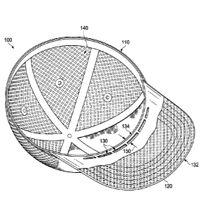
[0014] FIGURE 1 illustrates an underside view 100 of an exemplary hat 110
according
to an embodiment. Hat 110 comprises a unique design and configuration that
provides for airflow
around and over the head of a wearer. Hat 110 comprises a multiple port
ventilation system that
combines one or more intake ports 130 with one or more exhaust ports 140 to
circulate airflow
around and over the head of a wearer.
[0015] According to embodiments, the brim 120 may protrude outward from the
base
(e.g., bottom perimeter 180) of the hat 110, The brim 120 may comprise a front
portion 132 that
is also the front portion of the hat 110 and a back portion 134 (e.g., with a
curved edge) that
contacts with a wearer's head at the base of the hat 110. In addition, the
brim 120 of hat 110 may
3
Date Recue/Date Received 2020-04-17
comprise one or more intake ports 130 placed along the back portion 134 of the
brim 120 in front
of the portion of the hat 110 which that engages a wearer's head (e.g.,
flexible band 182). The one
or more intake ports 130 placed in brim 120 creates a gap 150 between the
front of a wearer's head
and the front of the intake parts 130 of the brim 120 of the hat 110. The
size, position and placement
of the intake ports 130 (as discussed below in more detail) create in input or
output of the gap 150
and direct air that flows under the brim 120 though the intake ports 130 and
into the gap 150 (e.g.,
channel 184), around and over the wearer's head, and then flowing out the
exhaust ports 140. In
addition, and as discussed in more detail below, air may flow from one or more
exhaust ports 140,
around and over the wearer's head, through the gap 150 and out the intake
ports 130 under the
brim 120 in the front of the wearer's head. That is, in order to increase the
airflow around and over
the wearer's head, one or more exhaust ports 140 may be coupled to another
portion of the hat 110
that allows air from the intake ports 130 to flow out of the hat 110.
[0016] According to embodiments, the hat 110 may comprise one or more exhaust
ports
140 on the sides or the back of the hat 110. The air that enters the intake
ports 130 in the front of
the hat 110 may flow around and over the head of the wearer and through the
one or more exhaust
ports 140 in the back or sides of the hat 110. In this way, air may flow in
through the front of the
hat 110 and out through the back of the hat 110.
100171 Although the intake ports 130 are shown and described substantially at
the
front of the hat 110, and the exhaust ports 140 are described substantially on
the sides or on
the back of the hat 110, embodiments contemplate any number or location of the
intake ports
130 and the exhaust ports 140, according to particular needs. For example,
locating the intake
ports 130 on the front of the hat 110 under the brim 120 allows air collected
under the brim
120 to be funneled up into the intake ports 130, through the gap 150, around
and over the
wearer's head, and exit the exhaust ports 140. In fact, the disclosed
embodiments create a
4
Date Recue/Date Received 2020-04-17
CA 03038060 2019-03-22
WO 2018/057976 PCT/1JS2017/053084
particularly strong air flow by collecting a large amount of air from under
the surface area of
the brim 120 and channeling that air though the gap 150 in the front of the
wearer's head
creating a strong cooling sensation. In addition, or as an alternative, any
heat created from the
wearer's head causes an air differential thereby increasing the airflow around
and over the
wearer's head and into and out of the intake ports 130 and exhaust ports 140.
[0018] According to some embodiments, the intake ports 130 and the exhaust
ports
140 are sized to allow sufficient airflow to circulate around the wearer's
head. According to
embodiments, the exhaust port 140 is sized such that all air that flows in
through the intake
ports 130 is easily exhausted through the exhaust ports 140. Additionally, the
intake ports 130
and the exhaust ports 140 may be sized to take into account the thermodynamic
properties of
the heat radiated by the head of the wearer. For example, the intake ports 130
and the exhaust
ports 140 are sized to dissipate the heat from the head of a typical wearer.
However, the
intake ports 130 and exhaust ports 140 may be sized larger or smaller based on
the amount of
heat given off by the wearer, the size and type of hat 110, and/or the ambient
heat of the
environment.
[0019] Additionally, the intake ports 130 and the exhaust ports 140 may be
sized to
accommodate different wind environments. According to embodiments, the intake
ports 130
and the exhaust ports 140 may be sized to allow sufficient wind to pass
through the hat 110,
such that, the wind does not blow the hat 110 off of the wearer's head. For
example, the
intake ports 130 may comprise a smaller size opening so that increased airflow
through the
hat 110 does not blow the hat 110 off of the wearer's head. Additionally, or
in the alternative,
the exhaust ports 140 may be over-sized so that any amount of air that goes
into the hat 110
may freely escape without blowing the hat 110 off of the wearer's head. In
other words, if the
exhaust ports 140 are too small, the hat 110 may blow off of the wearer's
head.
SUBSTITUTE SHEET (RULE 26)
CA 03038060 2019-03-22
WO 2018/057976 PCT/1JS2017/053084
[0020] FIGURE 2 illustrates a side view 200 of the hat 110 of FIGURE 1
according
to an embodiment. According to embodiments, the hat 110 comprises the brim 120
and the
crown 160 that covers the crown of a wearer's head. The crown 160 may comprise
a front of
the crown 162, a back of the crown 164 and sides of the crown 166. According
to
embodiments, the hat 110 comprises one or more exhaust ports 140 on the back
of the crown
164 and/or on the sides of the crown 166. According to embodiments, the
exhaust ports 140
serves as a ventilation system for the hat 110, as described in more detail
herein. In one
embodiment, the surface area of the exhaust port 140 is sized sufficiently
larger than the
surface area of intake ports 130, so that the amount of air that flows through
the intake ports
130 is allowed to quickly exhaust, without impeding air flow. Conversely, the
surface area of
the exhaust port 140 is sized sufficiently larger than the surface area of
intake ports 130, such
that air may flow into exhaust port 140 and flow out of intake port 130, in
for example, windy
conditions.
100211 According to embodiments, the exhaust ports 140 comprise a mesh or
perforated surface formed from fabric, polymers, or other suitable materials.
[0022] Although, the exhaust ports 140 are shown to cover substantially the
back of
the crown 164 and sides of the crown 166 embodiments contemplate, any size,
configuration
or placement of the exhaust ports 140, according to particular needs.
[0023] FIGURE 3 illustrates an exemplary back view 300 of the inside of the
hat 110
of FIGURE 1 according to an embodiment. As can be seen, the intake ports 130
in the brim
120 of the hat 110 may be located between the back portion 134 of the brim 120
and the front
of the crown 162, thereby creating the gap 150. According to embodiments, this
gap 150 is
formed by extending the material of the brim 120 material inward toward the
wearer's head
so that the material of the brim 120 holds the front of the hat 110 outward
from the head of
6
SUBSTITUTE SHEET (RULE 26)
CA 03038060 2019-03-22
WO 2018/057976 PCT/1JS2017/053084
the wearer, which creates the gap 150 between the front of the crown 162 and
the wearer's
head and allows for airflow along the forehead of a wearer's head.
[0024] Although the gap 150 is created by the brim 120, embodiments
contemplate
forming a gap 150 above the intake ports 130 and in front of the wearer's head
by other
suitable configurations, such as, for example, placing spacers or cushioning
in front of the
head of the user that creates a gap 150 in front of the head of the user. In
addition, or as an
alternative, although the brim 120 is shown and described at the front of the
hat 110,
embodiments contemplate the brim 120 being at any portion of the hat 110, such
as, the back,
the sides or all the way around the hat 110, depending on the style of hat. In
these
embodiments, the one or more intake ports 130 and one or more exhaust ports
140 may be
located in the gap 150 between the front of the crown 162, back of the crown
164 and/or the
sides of the crown 166 and the wearer's head.
[0025] According to embodiments, the intake ports 130 may then be covered by a
breathable net or mesh (such as a fabric) so that the intake ports 130 are
hidden behind the net
or mesh to improve the aesthetic appearance of the hat 110 while not blocking
airflow.
According to some embodiments, the fabric may comprise openings that allow air
to flow
through the intake ports 130 and through or around the fabric.
[0026] According to other embodiments, the brim 120 material may be sewn
inside a
fabric covering the intake ports 130 either covered by a fabric or mesh or
partially visible on
the underside of the hat 110. In either configuration, the intake ports 130
provide for air
traveling underneath the brim 120 to be directed over the wearer's head
through the gap 150
between the front of the crown 162 and the wearer's head.
[0027] FIGURE 4 illustrates an exemplary back view 400 of the inside of the
hat 110
of FIGURE 1 including a flexible band 410 according to another embodiment. For
some hats
7
SUBSTITUTE SHEET (RULE 26)
CA 03038060 2019-03-22
WO 2018/057976 PCT/1JS2017/053084
110, such as a baseball cap, the brim 120 is sewn to the front of the hat 110.
Although
examples are shown and described with respect to baseball caps, embodiments
contemplate
various features of the disclosed embodiments being formed into cowboy hats,
safari hats,
beach hats, or any other hat, helmet, or head gear.
100281 According to some embodiments, the hat 110 comprises a band 410 on the
inside of the hat 110. According to one embodiment, the flexible band 410 may
comprise an
elastic material, such as, for example, such that the flexible band 410 is
configured to grip the
wearer's head. According to some embodiments, the intake ports 130 may be
coupled to the
inside of the brim 120 on the side of the flexible band 410 away from the
wearer's head. In
this way, the air flows through the intake ports 130 and through the gap 150
that is between
the flexible band 410 and the front of the crown 162 of the hat 110, thereby
cooling the
flexible band 410. The gap 150 between the flexible band 410 and the front of
the crown 162
may be configured, such that there is a quarter of an inch in width associated
with the gap
150. Although a particular gap 150 is given as an example, embodiments
contemplate larger
or smaller gaps, according to particular needs. According to some embodiments,
the flexible
band 410 is tapered to fit wearer heads of various sizes.
100291 Additionally, the flexible band 410 may comprise a stiffened portion
that
allows the flexible portion to tightly grip the wearer's head while forming a
gap 150 between
the front of the crown 162 and the wearer's head. The shape of a wearer's
head, which
ordinarily slopes backward away from the front of the hat 110, may be used to
create a
tapered gap 150 between the wearer's forehead and the front of the crown 162
by shaping the
front of the crown 162 at a shallower angle than that of a typical forehead.
100301 FIGURE 5 illustrates an underside view 500 with an alternate
configuration of
the brim 120 including intake ports 130 and structural tabs 510 according to
an embodiment.
8
SUBSTITUTE SHEET (RULE 26)
CA 03038060 2019-03-22
WO 2018/057976 PCT/1JS2017/053084
According to embodiments, the brim 120 of the hat 110 may comprise one or more
structural
tabs 510 placed alongside the back edge of the brim 120 between the intake
ports 130 and the
front of the wearer's head. According to embodiments, the structural tabs 510
on the brim
120 of the hat 110 may be configured to increase the grip of the brim 120 to
the hat 110 and
help the intake ports 130 direct air that flows under the brim 120 into the
gap 150 in the front
of the wearer's head.
[0031] According to embodiments, the structural tabs 510 are substantially
perpendicular to the brim 120 and may fold upward at the back of the brim 120
between the
intake ports 130 and the front of the wearer's head. In addition, or as an
alternative, the
structural tabs 510 may be substantially aligned with the angle of the front
of the crown 162
According to embodiments, the structural tabs 510 are formed from a semi-rigid
material,
such as bendable plastic, that may be incorporated into the brim 120 of the
hat 110. Although
a particular material is shown and described, embodiments contemplate any type
of materials
for the brim 120 and the structural tabs 510, according to particular needs.
[0032] According to embodiments, the brim 120 may comprise a certain number of
structural tabs 510 folded up towards the inside edge of the hat 110. The
structural tabs 510
may be sized such that the brim 120 of the hat 110 is not enlarged from what
is suitable to a
particular style of hat 110. According to embodiments, the structural tabs 510
are embedded
within the edge of the brim 120 such that the brim 120 does not increase in
size According to
some embodiments, the structural tabs 510 are sized and spaced as shown, such
that the
structural tabs 510 may be four times the size of the spacing 520 between the
structural tabs
510. Although particular sizes of structural tabs 510 and spacing 520 between
the structural
tabs 510 are shown and described, embodiments contemplate any suitable size of
structural
tabs 510 or spacing 520 between the structural tabs 510, according to
particular needs.
9
SUBSTITUTE SHEET (RULE 26)
CA 03038060 2019-03-22
WO 2018/057976 PCT/1JS2017/053084
[0033] According to one embodiment, the brim 120 may comprise twenty
structural
tabs 510, no structural tabs 510, or any number of structural tabs 510.
Although a particular
number of structural tabs 510 have been shown and described, embodiments
contemplate any
number of structural tabs 510, according to particular needs. Additionally, or
as an
alternative, structural tabs 510 may each form a substantially square or
rectangular shape
Although particular shapes and numbers of structural tabs 510 have been
described,
embodiments contemplate any shape, any number of shapes, or number of
structural tabs 510,
according to particular needs.
[0034] FIGURE 6 illustrates a top view 600 of the inside of the hat 110 of
FIGURE 5,
according to an embodiment As can be seen, the intake ports 130 in the brim
120 of the hat
110 may be located between the structural tabs 510 of the brim 120 and the
front of the crown
162, thereby creating the gap 150. According to embodiments, this gap 150 is
formed by
extending the material of the brim 120 material inward toward the wearer's
head so that the
material of the brim 120 holds the front of the hat 110 outward from the head
of the wearer,
which creates the gap 150 between the front of the crown 162 and the
structural tabs 510,
thereby allowing for airflow along the forehead of a wearer's head.
[0035] According to one embodiment, a flexible band 410 is configured to grip
the
wearer's head, as discussed above in FIGURE 4. According to some embodiments,
the
flexible band 410 may be coupled to the structural tabs 510 of the brim 120,
thereby creating
the gap 150 between the flexible band 410 and the front of the crown 162. In
this way, the air
flows through the intake ports 130 and through the gap 150 that is between the
structural tabs
150 and the front of the crown 162 of the hat 110, thereby cooling the
flexible band 410
Additionally, the structural tabs 510 provides a stiffened portion to the
flexible band 410, as
SUBSTITUTE SHEET (RULE 26)
CA 03038060 2019-03-22
WO 2018/057976 PCT/1JS2017/053084
discussed above, that allows the flexible portion to tightly grip the wearer's
head while
forming a gap 150 between the front of the crown 162 and the wearer's head.
[0036] FIGURES 7A-7E illustrate exemplary embodiments of the intake parts 130
of
the brim 120, according to an embodiment. According to embodiments, the intake
ports 130
are formed from a semi-rigid material, such as a bendable plastic, that may be
incorporated
directly into the brim 120 of the hat 110. According to embodiments, the
intake ports 130
may comprise one or more openings through the brim 120 material. According to
embodiments, the brim 120 may comprise four intake ports 130 (as illustrated
in FIGURE
7A), six intake ports 130 (as illustrated in FIGURES 7B, 7C and 7E) or ten
intake ports 130
(as illustrated in FIGURE 7D) Although a particular number of intake ports 130
are shown
and described, embodiments contemplate any number of intake parts 130,
according to
particular needs.
[0037] Additionally, or in the alternative, the intake ports 130 that are
located toward
the center of the brim 120 may be wider than the intake ports 130 located at
the sides of the
brim 120. According to some embodiments, openings toward the sides of the brim
130 may
be tapered away from the center of the brim 130, such that, the intake ports
130 form a
substantially triangular shape that decreases the width of the intake ports
130, at the sides of
the hat 110. This may improve comfort to the wearer while also allowing
suitable airflow
through the intake ports 130
[0038] According to embodiments, the brim 120 may comprise an increased number
of intake ports 130, such as ten intake parts 130, shown in FIGURE 7D, which
allow for an
increased number of reinforcement 710 between each of the one or more intake
ports 130.
This may increase rigidity of the brim 120, while still allowing sufficient
airflow through the
intake ports 130.
11
SUBSTITUTE SHEET (RULE 26)
CA 03038060 2019-03-22
WO 2018/057976 PCT/1JS2017/053084
[0039] The intake ports 130 may be sized such that the brim 120 of the hat 110
is not
enlarged from what is suitable to particular style of hat 110. For example, a
baseball cap may
comprise a brim 120 of a particular size and configuration. According to
embodiments, the
intake ports 130 are embedded within the brim 120 such that the brim 120 does
not increase
in size. According to some embodiments, the intake ports 130 are between one-
eighth and
three-eighths of an inch in width. According to other embodiments, the intake
ports 130 are
between one-sixteenth and three-sixteenths of an inch in width. According to
yet other
embodiments, the reinforcements 710 are between one-sixteenth and one-quarter
of an inch
in width. Although particular sizes of intake ports 130 and reinforcements 710
are shown and
described, embodiments contemplate any suitable size of openings or
reinforcements,
according to particular needs.
[0040] According to embodiments, the material of the brim 120 comprises a semi-
rigid or flexible substrate, such as, for example, polymer, foam, stiffened
fabric, or other like
materials. According to other embodiments, embodiments contemplate the brim
120 formed
of a single piece, and coupled with the hat 110 by sewing, adhesive, or the
like.
[0041] Although features of the hat 110 apparatus are illustrated as
comprising
various components, embodiments contemplate any feature being composed of more
than one
piece or multiple features being combined into a single piece, according to
particular needs.
Additionally, embodiments contemplate any feature coupling with any other
feature by any
suitable coupling of components such as with adhesive, sewing, a fastener
(e.g. a bolt and a
nut, a screw, a clip, a rivet, a pin, hook and loop fastener, and/or the
like), washers, retainers,
straps, wrapping, wiring, a weld joint, a solder joint, and any combination of
the foregoing.
100421 Although specific materials for each of the features of the present
disclosure
have been presented, embodiments contemplate various types of materials or
combinations
12
SUBSTITUTE SHEET (RULE 26)
CA 03038060 2019-03-22
WO 2018/057976 PCT/1JS2017/053084
thereof that can readily be formed into shaped objects provided that the
materials selected are
consistent with the intended operation of the hat apparatus. For example, the
components
may be formed of: fabrics, polymers, such as thermoplastics and thermosets;
rubbers
(synthetic and/or natural); composites, such as carbon-fiber; metals; alloys;
any other suitable
material; and/or any combination of the foregoing.
[0043] Reference in the foregoing specification to "one embodiment", "an
embodiment", or "some embodiments" means that a particular feature, structure,
or
characteristic described in connection with the embodiment is included in at
least one
embodiment of the invention. The appearances of the phrase "in one embodiment"
in various
places in the specification are not necessarily all referring to the same
embodiment.
[0044] While the exemplary embodiments have been shown and described, it will
be
understood that various changes and modifications to the foregoing embodiments
may
become apparent to those skilled in the art without departing from the spirit
and scope of the
present invention.
13
SUBSTITUTE SHEET (RULE 26)