Language selection

Search

Patent 3038609 Summary

Third-party information liability

Some of the information on this Web page has been provided by external sources. The Government of Canada is not responsible for the accuracy, reliability or currency of the information supplied by external sources. Users wishing to rely upon this information should consult directly with the source of the information. Content provided by external sources is not subject to official languages, privacy and accessibility requirements.

Claims and Abstract availability

Any discrepancies in the text and image of the Claims and Abstract are due to differing posting times. Text of the Claims and Abstract are posted:

  • At the time the application is open to public inspection;
  • At the time of issue of the patent (grant).
(12) Patent Application: (11) CA 3038609
(54) English Title: WORK PLATFORM WITH EXTENSION DECK AND WORK STEP
(54) French Title: PLATEFORME DE TRAVAIL COMPORTANT UN PLATEAU DE RALLONGE ET UNE MARCHE
Status: Examination Requested
Bibliographic Data
(51) International Patent Classification (IPC):
  • E04G 1/22 (2006.01)
  • B66F 11/04 (2006.01)
  • E04G 1/15 (2006.01)
(72) Inventors :
  • CROOK, GARY (United States of America)
(73) Owners :
  • CALIFORNIA MANUFACTURING AND ENGINEERING CO., LLC (United States of America)
(71) Applicants :
  • CALIFORNIA MANUFACTURING AND ENGINEERING CO., LLC (United States of America)
(74) Agent: SMART & BIGGAR LP
(74) Associate agent:
(45) Issued:
(22) Filed Date: 2019-04-01
(41) Open to Public Inspection: 2019-10-27
Examination requested: 2024-03-22
Availability of licence: N/A
(25) Language of filing: English

Patent Cooperation Treaty (PCT): No

(30) Application Priority Data:
Application No. Country/Territory Date
62/663465 United States of America 2018-04-27
16/275854 United States of America 2019-02-14

Abstracts

English Abstract


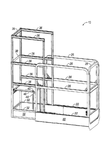
A self-propelled aerial work platform apparatus includes a chassis and
elevating work
platform with operator controls thereon. The work platform includes a main
deck, an extension
deck and a storable work step at one end of the extension deck to allow a
worker to access utilities
through openings in drop ceilings. The step and attached legs are moveable
together from a
horizontal work position of the step to a vertically extending storage
position with step and legs
alongside the step close to guardrails at the end of the extension deck.


Claims

Note: Claims are shown in the official language in which they were submitted.


Claims:
1. A work platform for use in aerial work platform apparatus, said work
platform
comprising a main deck, an extension deck supported on said main deck, said
extension deck
having a floor, guardrails and a work step, said step being moveable from a
work position in which
it is horizontally oriented above said floor to a storage position when not in
use.
2. The work platform of claim 1, including at least one hinge connecting
said step to
support structure on said extension deck.
3. The work platform of claim 2, further including at least one step
support leg and a
hinge connecting said step to said support leg.
4. The work platform of claim 3, including two of said support legs and
hinges, said
hinges connecting said support legs to spaced sides of said step thereby
permitting said legs to
pivot alongside said step from a step support position into a vertically
extending storage position
of said step and legs.
5. The work platform of claim 4, wherein said floor of said extension deck
includes
retainers for securing ends of said legs when said step is in said work
position.
6. The work platform of claim 5, wherein said guardrails on said extension
deck
include upper sections moveable from lowered storage positions to elevated
safe height positions.
7. The work platform of claim 6, wherein said upper guardrail sections
include legs
telescopically received in legs of lower guardrail sections.
7


8. An aerial work platform apparatus comprising:
a) a self-propelled chassis;
b) a work platform operably supported by said chassis for elevation to a
work
position;
c) a lift mechanism on said chassis operably connected to said work
platform
for elevating said platform to a work elevation;
d) controls on said work platform accessible to an operator on said
platform
for moving the apparatus and for elevating and lowering said work platform;
and
e) said work platform including a main deck, an extension deck supported on

said main deck, said extension deck having a floor, guardrails and a and a
work step, said step
being pivotally moveable from a horizontally oriented work position to a
vertically oriented
storage position.
9. The apparatus of claim 8, including at least one hinge connecting
said step to a
horizontally extending cross brace at one end of said extension deck.
10. The apparatus of claim 9, further including at least one step
support leg and a hinge
connecting said step to said support leg.
11. The apparatus of claim 10, including two of said support legs and
hinges connecting
said support legs to spaced sides of said step thereby permitting said legs to
pivot alongside said
step from a step support position into a vertically extending storage position
of said step and legs.
12. The apparatus of claim 11, wherein said floor of said extension
deck includes
retainers for securing ends of said support legs in position when said step is
in said work position.
13. The apparatus of claim 12, wherein said retainers comprise
apertures for receiving
portions of said support legs when said step is in said work position.

8


14. The apparatus of claim 13, wherein said guardrails on said extension
deck include
upper sections moveable from lowered storage positions to elevated safe height
positions.
15. The apparatus of claim 14, wherein said upper guardrail sections
include legs
telescopically received in vertically extending legs of lower guardrail
sections.
16. The apparatus of claim 15, wherein said lift mechanism is a scissors
mechanism.

9

Description

Note: Descriptions are shown in the official language in which they were submitted.


WORK PLATFORM WITH EXTENSION DECK AND WORK STEP
Background of the Invention and Prior Art
Field of the Invention
This disclosure pertains to self-propelled aerial work platform apparatus,
particularly small
size self-propelled scissors lifts which are controllable and moveable by an
operator from the work
platform.
Description of the Related Art:
Scissors lifts are in widespread use in warehouses, construction sites and
various other job
sites. With the increasing use of low-level aerial work platforms to perform
elevated work tasks
in safer and more productive methods, there is a need for means to work
through small overhead
openings. A typical application is the need to work on utility services such
as electric and
communication cables, water and gas pipes and the like which are secured to
structural ceilings
having drop ceilings suspended below the utilities. Since access openings
which may be made in
the drop ceiling are typically less than 24" wide, the work platform
guardrails restrict elevation of
the platform above the suspended drop ceiling thereby preventing the worker
from conveniently
reaching the utilities above the drop ceiling for installation, replacement or
repair. This limitation
causes workers to consider standing on the platform guardrail mid-rail or use
a small ladder on the
platform, both of which are unsafe and forbidden practices. The traditional
solution is the use of
a specialized "push around" personnel lift that typically has a small platform
which by definition
is not self-propelled. A further limitation of the push around platform type
lift is that once the lift
is positioned and the platform stabilizing outriggers have been set, the
vertical projection of the
1
CA 3038609 2019-04-01

platform is fixed in place and re-positioning of the lift and re-deployment of
the outriggers may be
necessary to allow a worker to enter through a tight overhead opening in the
drop ceiling.
One solution of this problem is a vertical access platform attachment called
SHU device
offered by Man Lift Manufacturing Co. for a self-propelled scissor lift. The
attachment allows a
worker to reach higher but replaces the existing slide out deck and therefore
not only eliminates
this advantageous feature but also causes the apparatus to be significantly
longer thereby making
it less maneuverable in tight spaces, restriction for entering a freight
elevator and for loading onto
a delivery vehicle. Such devices are heavy causing the lift capacity to be
reduced. In addition,
the attachment is relatively expensive and not instantly available or readily
installed
Summary of the Disclosure
A platform of the type having an extension deck for use in aerial work
platform apparatus.
The work platform comprises a main deck and an extension deck with guardrails
and an attached
moveable step. Guardrails having raiseable upper sections are provided on the
extension deck.
The step is moveable from a work position in which it is horizontally oriented
above the extension
deck to a storage position when not in use.
This work platform is particularly adapted for use on small aerial work
apparatus which
has a self-propelled chassis and mechanism such as a scissors lift on the
chassis for elevating the
platform to a work position. Operator controls are provided on the work
platform for positioning
the apparatus and for elevating and lowering the work platform.
Brief Description of the Drawings
2
CA 3038609 2019-04-01

=
Figure 1 is a perspective view of a work platform for an aerial work platform
apparatus,
the platform including an extension deck and a folding step.
Figure 2 is a perspective view of the platform of Fig. 1 showing the step in
folded position.
Figure 3 is perspective view of the extension deck with step and associated
guardrails
extended.
Figure 4 is a perspective view like Fig. 3 viewed from a different angle with
the step and
associated guardrails stowed.
Figure 5 is another perspective view of the entire work platform showing the
extension
deck extended from the main work deck with raiseable guard rails on the
extension deck in a
stowed position and the step in folded position.
Figure 6 is a perspective view like Figure 5 showing the step in operative
position and
guard rails associated with the step deployed in raised position.
Figure 7 is a perspective view of the extension deck and hinged connection of
the step
shown in stowed position.
Figure 8 is a perspective view of the extension deck with the step and
guardrails in
operative position.
Figure 9 is a perspective view of the main deck and extension deck in
retracted position.
3
CA 3038609 2019-04-01

Figure 10 is a perspective view like Figure 9 with the step and guardrails in
operative
position.
Description of Presently Preferred Embodiment
The work platform 10 is of generally rectangular configuration and includes a
main deck
20, an extension deck 30 and a storable step 40 particularly useful on small
aerial work apparatus
such as a scissors lift. The main deck 20 of the platform includes
longitudinally extending
structural members 22 affixed to and supporting a generally flat floor or
bottom 24, spaced side
guardrails 26 and an access gate 28 at one end. The extension deck 30 includes
longitudinally
extending structural members 32 supporting a flat floor or bottom 34. The
structural members 32
of the extension deck 30 are slideably received between and supported by the
structural members
22 of the main deck such that the floor 34 of the extension deck is slightly
above the floor 24 of
the main deck 20. It will be noted from Figs. 5 through 10 that the bottom 34
of the extension
deck 30 has a cutout area 35 at the end facing the gate so that the operator
can stand on the floor
24 of the main deck and manually extend and retract the extension deck 30 when
desired. Spaced
side and end guardrails 36, 38 of the extension deck 30 are sized and
connected as shown such that
the extension deck and its guardrails may be stowed above the main deck 20.
Stops (not shown)
are provided as is conventional to define the safe limits of travel of the
extension deck 30. Upper
sections of the side guardrails on the extension deck may be lowered from the
Fig. 1 position to
the Fig. 2 position by telescopically sliding the upper guardrail support legs
into or alongside the
guardrail support legs immediately below.
A moveable step 40 for safety purposes is preferably of rectangular
configuration and
extends substantially the full width of the extension deck 30 to provide an
elevated step up work
platform when needed. The edge of the step nearest the end of the extension
deck is affixed,
preferably by a pair of hinges 42, to support structure such as a guardrail
cross brace 38 of the
4
CA 3038609 2019-04-01

extension deck such that the unhinged end of the step 40 may be lifted from a
horizontally
extending working elevation above the floor 34 of the extension deck to a
vertically extending
storage position at the end of the extension deck when not in use. The step 40
includes pivotally
connected support legs 44 preferably having configuration such as short
projections at the ends
thereof to be received in retainers such as positioning pockets 46 in the
floor 34 of the extension
deck when the step is in its horizontal work position. Applicable safety and
operating instructions
can be displayed on the floor 34 of the extension deck 30 to be visible when
the step 40 is in its
horizontally extended position and/or on the underside of the step to be
visible when the step is in
its vertical storage position.
Upper moveable guardrail sections of the extension deck 30 are provided to
protect a
worker when standing on the step 40. The upper guardrail sections may be
manually lifted from
lowered positions in which their vertical legs are preferably telescopically
stored inside or
alongside vertical legs of the lower extension deck guardrail sections. The
upper sections of the
guardrails 36 may be retained in either the stored position or in the work
position by T handle pull
pins 39 (Figs. 5 - 10) which engage with holes in the vertically extending
guardrail legs. If desired,
powered means may be provided to assist lifting the upper guardrail sections
to operable position.
=As seen in Figures 7 and 8, the step 40 is connected along a pivot axis to
supporting
structure on the extension deck such as a guardrail cross brace 38 by a hinge
or hinges 42 and the
step support legs 44 are preferably pivotally connected at 45 to the step 40
to be located closely
alongside the step support surface when the step is pivotally raised to its
stored location. The step
40 and legs 44 may be secured to a guardrail by temporary fastening means such
as snap retainers,
the step 40 then occupying its stored position between the vertically
extending corner guardrail
legs. Alternatively, it may be preferred to swing the step to a storage
position below the hinges 42
instead of above. An operator control station 50 is provided in any suitable
location on the
extension deck 30 as seen in Figs. 5 and 6.
5
CA 3038609 2019-04-01

=
The above described embodiment provides a significant improvement to more
easily allow
workers to minimize re-positioning of the aerial work platform and step up to
better reach into and
above small access openings such as those in drop ceilings to work on
utilities suspended from
structural ceilings.
Various modifications of the presently preferred embodiment shown and
described above
may be made without departing from the scope of protection of the claims which
follow.
6
CA 3038609 2019-04-01

Representative Drawing
A single figure which represents the drawing illustrating the invention.
Administrative Status

For a clearer understanding of the status of the application/patent presented on this page, the site Disclaimer , as well as the definitions for Patent , Administrative Status , Maintenance Fee  and Payment History  should be consulted.

Administrative Status

Title Date
Forecasted Issue Date Unavailable
(22) Filed 2019-04-01
(41) Open to Public Inspection 2019-10-27
Examination Requested 2024-03-22

Abandonment History

There is no abandonment history.

Maintenance Fee

Last Payment of $277.00 was received on 2024-03-01


 Upcoming maintenance fee amounts

Description Date Amount
Next Payment if small entity fee 2025-04-01 $100.00
Next Payment if standard fee 2025-04-01 $277.00

Note : If the full payment has not been received on or before the date indicated, a further fee may be required which may be one of the following

  • the reinstatement fee;
  • the late payment fee; or
  • additional fee to reverse deemed expiry.

Patent fees are adjusted on the 1st of January every year. The amounts above are the current amounts if received by December 31 of the current year.
Please refer to the CIPO Patent Fees web page to see all current fee amounts.

Payment History

Fee Type Anniversary Year Due Date Amount Paid Paid Date
Application Fee $400.00 2019-04-01
Registration of a document - section 124 $100.00 2019-12-10
Maintenance Fee - Application - New Act 2 2021-04-01 $100.00 2021-03-04
Maintenance Fee - Application - New Act 3 2022-04-01 $100.00 2022-03-01
Maintenance Fee - Application - New Act 4 2023-04-03 $100.00 2023-03-29
Maintenance Fee - Application - New Act 5 2024-04-02 $277.00 2024-03-01
Request for Examination 2024-04-02 $1,110.00 2024-03-22
Owners on Record

Note: Records showing the ownership history in alphabetical order.

Current Owners on Record
CALIFORNIA MANUFACTURING AND ENGINEERING CO., LLC
Past Owners on Record
None
Past Owners that do not appear in the "Owners on Record" listing will appear in other documentation within the application.
Documents

To view selected files, please enter reCAPTCHA code :


To view images, click a link in the Document Description column. To download the documents, select one or more checkboxes in the first column and then click the "Download Selected in PDF format (Zip Archive)" or the "Download Selected as Single PDF" button.

List of published and non-published patent-specific documents on the CPD .

If you have any difficulty accessing content, you can call the Client Service Centre at 1-866-997-1936 or send them an e-mail at CIPO Client Service Centre.


Document
Description 
Date
(yyyy-mm-dd) 
Number of pages   Size of Image (KB) 
Abstract 2019-04-01 1 13
Description 2019-04-01 6 205
Claims 2019-04-01 3 76
Drawings 2019-04-01 10 366
Representative Drawing 2019-09-16 1 13
Cover Page 2019-09-16 1 42
Request for Examination 2024-03-22 5 112
Modification to the Applicant/Inventor 2023-06-27 5 132
Name Change/Correction Applied 2023-09-27 1 227
Modification to the Applicant/Inventor 2023-09-28 5 133
Name Change/Correction Applied 2023-10-06 1 226