Language selection

Search

Patent 3038724 Summary

Third-party information liability

Some of the information on this Web page has been provided by external sources. The Government of Canada is not responsible for the accuracy, reliability or currency of the information supplied by external sources. Users wishing to rely upon this information should consult directly with the source of the information. Content provided by external sources is not subject to official languages, privacy and accessibility requirements.

Claims and Abstract availability

Any discrepancies in the text and image of the Claims and Abstract are due to differing posting times. Text of the Claims and Abstract are posted:

  • At the time the application is open to public inspection;
  • At the time of issue of the patent (grant).
(12) Patent Application: (11) CA 3038724
(54) English Title: SCREW WITH SOCKET HEAD
(54) French Title: VIS A TETE CREUSE
Status: Report sent
Bibliographic Data
(51) International Patent Classification (IPC):
  • F16B 23/00 (2006.01)
(72) Inventors :
  • PEREGO, FRANCESCO (Italy)
(73) Owners :
  • FONTANA FASTENERS R.D. S.R.L. (Italy)
(71) Applicants :
  • FONTANA FASTENERS R.D. S.R.L. (Italy)
(74) Agent: SMART & BIGGAR LP
(74) Associate agent:
(45) Issued:
(86) PCT Filing Date: 2017-10-02
(87) Open to Public Inspection: 2018-04-12
Examination requested: 2022-09-08
Availability of licence: N/A
(25) Language of filing: English

Patent Cooperation Treaty (PCT): Yes
(86) PCT Filing Number: PCT/IB2017/056061
(87) International Publication Number: WO2018/065877
(85) National Entry: 2019-03-28

(30) Application Priority Data:
Application No. Country/Territory Date
102016000099434 Italy 2016-10-04

Abstracts

English Abstract

The screw (10) has a longitudinal axis (12) and comprises a threaded shank (13) and a head (14) wherein a socket (16) is formed to be engaged by a wrench and having a pluri-lobed outer profile comprising a series of lobes (18) circumferentially offset and separated by a series of circumferentially offset protrusions (20) of the head (14). Each protrusion is delimited by two flanks (22) and a front length (24) joining the radially inner ends of the flanks (22) and is convex and symmetrical with respect to a center axis (26) radially oriented with respect to the longitudinal axis (12). The front length (24) is formed by a center face (28) and two inclined side faces (30) each of which joins the radially inner end of the respective flank (22) with a respective end of the center face (28), which is oriented orthogonally with respect to the center axis (26) of the protrusion (20).


French Abstract

L'invention concerne une vis (10) ayant un axe longitudinal (12) et comprenant une tige filetée (13) et une tête (14) dans laquelle une cavité (16) est formée pour être mise en prise par une clé et ayant un profil extérieur à plusieurs lobes comprenant une série de lobes (18) décalés circonférentiellement et séparés par une série de protubérances décalées circonférentiellement (20) de la tête (14). Chaque protubérance est délimitée par deux flancs (22) et par une longueur avant (24) joignant les extrémités radialement intérieures des flancs (22) et est convexe et symétrique par rapport à un axe central (26) orienté radialement par rapport à l'axe longitudinal (12). La longueur avant (24) est formée par une face centrale (28) et par deux faces latérales inclinées (30) qui relient chacune l'extrémité radialement intérieure du flanc respectif (22) avec une extrémité respective de la face centrale (28), qui est orientée orthogonalement par rapport à l'axe central (26) de la protubérance (20).

Claims

Note: Claims are shown in the official language in which they were submitted.


5

CLAIMS

1. Screw (10) having a longitudinal axis (12) and comprising a threaded
shank and a
head (14) within which is formed a socket (16) intended to be engaged by a
wrench and
having a pluri-lobed external profile comprising a series of lobes (18)
circumferentially
offset and separated by a series of circumferentially offset protrusions (20)
of said head (14),
each protrusion (20) being delimited by two flanks (22) and a front length
(24) joining the
radially inner ends of said flanks (22) and being convex and symmetric with
respect to a
center axis (26) radially oriented with respect to said longitudinal axis
(12), said screw (10)
being characterized in that said front length (24) is formed by a center face
(28) and two
inclined side faces (30) each of which joins the radially inner end of the
respective flank (22)
with a respective end of the center face (28) which is orthogonally orientated
with respect to
said center axis (26) of the protrusion (20).
2. Screw (10) according to claim 1, wherein said two inclined side faces
(30) form an
angle in the range 155° to 174°, preferably 162°.
3. Screw (10) according to claim 1 or 2, wherein the facing flanks (22) of
two
consecutive protrusions (20) form an angle in the range 25° to
45°, preferably 34.8°.
4. Screw (10) according to any one of the previous claims, wherein the
ratio between
the length of said center face (28) and the distance between the radially
inner ends of said
flanks (22) is in the range 0.01 to 0.8.
5. Screw (10) according to any one of the previous claims, wherein said
lobes (18) and
said protrusions (20) are six and equi-spaced.
6. Screw (10) according to any one of the previous claims, wherein the
corners joining
the radially inner end of each flank (22) with said inclined side face (30)
and the radially
external end of each flank (22) with the bottom of said lobe (18) are rounded.
7. Screw (10) according to any one of the previous claims, wherein the
center face (28)


6

and the side faces (30) of the frontal portion of each protrusion (20) are
flat and intersect,
forming respective edges.
8. Pluri-
lobed wrench having an external profile which is complementary to the profile
of the socket (14) of the head (14) of a screw (10) according to any one of
the previous
claims.

Description

Note: Descriptions are shown in the official language in which they were submitted.


CA 03038724 2019-03-28
WO 2018/065877 PCT/IB2017/056061
1
Screw with socket head
The present invention relates to a screw with a socket head.
More specifically, such a screw has a longitudinal axis and comprises a
threaded shank and
a head in which a socket is formed to be engaged by a wrench and having a
pluri-lobed outer
profile comprising a series of lobes circumferentially offset and separated by
a series of
circumferentially offset protrusions of said head. Each protrusion is
delimited by two flanks
and a front length joining the radially inner ends of the flanks and is convex
and symmetrical
with respect to a center axis radially oriented with respect to said
longitudinal axis.
U.S. Patent No. 5 577 871 describes a screw of the type described above, which
may be
tightened with a special pluri-lobed wrench, with a profile complementary to
that of the
socket of the screw head, or with a conventional polygonal wrench.
However, such a known screw cannot be tightened in an "efficient" way and
without
tightening-induced deformations, which in the field of application compromise
the
possibility of multi-tightening with wrenches other than those indicated
above. Moreover,
tightening with a hexagonal wrench may still to cause a deformation of the
socket and thus
reduce the efficiency of such operation with respect to the case wherein the
special pluri-
lobed wrench with a complementary profile is used.
EP 2 441 971 Al describes a screw having the features indicated in the
preamble of claim 1,
wherein the front length of each protrusion is composed of two inclined side
faces that meet
at a center edge.
US 2012 137842 Al describes a socket head screw with an external pluri-lobed
profile,
whereby the lobes are separated by concave protrusions.
EP 1 693 577 Al describes a screw with a head wherein Y-shaped grooves are
formed.
An object of the present invention is therefore to remedy the aforementioned
drawbacks of

CA 03038724 2019-03-28
WO 2018/065877 PCT/IB2017/056061
2
the prior art.
According to this invention, such purpose is achieved by means of a screw
having the
features indicated in claim 1 hereinafter. Preferred and non-limiting features
of the screw of
the invention are indicated in the dependent claims.
In addition to using a specific wrench with a profile complementary to that of
the related
socket, the screw of the invention may also be tightened with a known pluri-
lobed wrench
of the "Torx" OD type or a conventional polygonal wrench, thus guaranteeing a
remarkable
versatility of use and an equal, if not increased, "tightening efficiency" in
accordance with
existing standards (e.g. ISO 4762 and ISO 14579) that provide dimensions of
the socket for
a given class of screws.
If the specific wrench with a complementary profile is used, the tightening of
screw of the
invention is carried out with increased efficiency. In this way, with the same
screwing torque
imposed, there is less deformation of the imprint of the screw's socket, which
translates into
a greater axial load (or "pull") of the same screw. The Cartesian torque/screw
angle diagram,
inherent to the screw of the invention, has a linear length with greater slope
and a limit of
linearity at a higher value of transmitted torque without causing undesirable
nonlinear
deformations with respect to the known socket screws mentioned above.
The screw of the invention also has the advantage of having a reduced mass
with respect to
the known screws with a pluri-lobed cavity, due to the fact that each
protrusion has a front
length with a center "flush" face, which does not diminish the efficiency of
the tightening,
lying in a plane orthogonal to a radial plane passing through the longitudinal
axis of the
screw and the center line of the aforementioned center face. The latter face
allows an optimal
insertion of the three possible wrenches mentioned above, in particular the
hexagonal
wrench. The insertion into the socket of this latter wrench is in fact
facilitated as there is no
longer the edge joining the inclined faces of the ridges interposed between
the lobes of the
socket of the screw claimed by US 5 577 871.
Another subject-matter of the present invention is a pluri-lobed wrench having
an external

CA 03038724 2019-03-28
WO 2018/065877 PCT/IB2017/056061
3
profile complementary to the profile of the socket of the head of the screw of
the invention.
Further advantages and features of this invention will become apparent from
the detailed
description that follows, provided by way of non-limiting example with
reference to the
accompanying drawings, wherein:
figure 1 is a schematic plan view of a screw of the invention, and
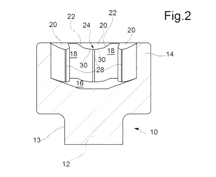
figure 2 is a sectional view according to the line II-II of figure 1.
A screw 10 has a longitudinal axis 12 and comprises a threaded shank 13 and a
head 14
within the center portion of which a socket 16 is provided open outwardly and
intended to
be engaged by a tightening tool such as a wrench.
The socket 16 has a pluri-lobed external profile comprising a series of lobes
18
circumferentially offset and separated by a series of circumferentially offset
protrusions 20
of the head 14. The lobes 18 and the protrusions 20 are six and equally
spaced, but, in
embodiments not illustrated, could be present in any whole number ranging from
2 to 12.
Each protrusion 20 is delimited by two flanks 22 and a front length 24 joining
the radially
inner ends of the flanks 22 and is convex and symmetrical with respect to a
center axis 26,
radially oriented with respect to the longitudinal axis 12 of the screw 10.
The top surface of
the protrusions 20 is further inclined towards the bottom of the socket 16
proceeding radially
inward. It goes without saying, moreover, being that every protrusion 20 is
convex, every
segment joining any two points of the respective top surface is entirely
contained in this
latter surface.
The front length 24 of each protrusion 20 is formed by a center face 28 and
two side faces
30, inclined with respect to the axis 26, each of which joins the radially
inner end of the
respective flank 22 with a respective end of the center face 28, which is
oriented orthogonally
with respect to the center axis 26.
The two inclined side faces 30 of each front length 24 form an angle p between
155 and
174 , and preferably 162 . The center face 28 and the side faces 30 are flat
and intersect,

CA 03038724 2019-03-28
WO 2018/065877 PCT/IB2017/056061
4
forming respective edges.
The facing flanks 22 of two consecutive protrusions 20 form an angle a in the
range of 25
to 45 , and preferably 34.8 .
Advantageously, the ratio between the length of the center face 28 and the
distance between
the radially inner ends of the flanks 22 of each protrusion 20 is between 0.01
and 0.8.
The edges joining respectively the radially inner end of each flank 22 with
the associated
inclined side face 30 and the radially outer end of each flank 22 with the
bottom of the
adjacent lobe 18 are rounded.
The screw 10 just described may be tightened not only with a specific wrench
with a profile
complementary to that of the socket 16, but also with a known, "Torx"0-type
pluri-lobed
wrench and a conventional hexagonal wrench, having the advantages described
above.
Naturally, without altering the principle of the invention, the details of
implementation and
embodiments may vary widely with respect to those described purely by way of
example,
without thereby departing from the scope of the invention as defined in the
appended claims.

Representative Drawing
A single figure which represents the drawing illustrating the invention.
Administrative Status

For a clearer understanding of the status of the application/patent presented on this page, the site Disclaimer , as well as the definitions for Patent , Administrative Status , Maintenance Fee  and Payment History  should be consulted.

Administrative Status

Title Date
Forecasted Issue Date Unavailable
(86) PCT Filing Date 2017-10-02
(87) PCT Publication Date 2018-04-12
(85) National Entry 2019-03-28
Examination Requested 2022-09-08

Abandonment History

Abandonment Date Reason Reinstatement Date
2024-04-03 FAILURE TO PAY APPLICATION MAINTENANCE FEE

Maintenance Fee

Last Payment of $203.59 was received on 2022-09-19


 Upcoming maintenance fee amounts

Description Date Amount
Next Payment if small entity fee 2023-10-03 $100.00
Next Payment if standard fee 2023-10-03 $277.00

Note : If the full payment has not been received on or before the date indicated, a further fee may be required which may be one of the following

  • the reinstatement fee;
  • the late payment fee; or
  • additional fee to reverse deemed expiry.

Patent fees are adjusted on the 1st of January every year. The amounts above are the current amounts if received by December 31 of the current year.
Please refer to the CIPO Patent Fees web page to see all current fee amounts.

Payment History

Fee Type Anniversary Year Due Date Amount Paid Paid Date
Application Fee $400.00 2019-03-28
Maintenance Fee - Application - New Act 2 2019-10-02 $100.00 2019-08-28
Maintenance Fee - Application - New Act 3 2020-10-02 $100.00 2020-09-21
Maintenance Fee - Application - New Act 4 2021-10-04 $100.00 2021-09-21
Request for Examination 2022-10-03 $814.37 2022-09-08
Maintenance Fee - Application - New Act 5 2022-10-03 $203.59 2022-09-19
Owners on Record

Note: Records showing the ownership history in alphabetical order.

Current Owners on Record
FONTANA FASTENERS R.D. S.R.L.
Past Owners on Record
None
Past Owners that do not appear in the "Owners on Record" listing will appear in other documentation within the application.
Documents

To view selected files, please enter reCAPTCHA code :


To view images, click a link in the Document Description column. To download the documents, select one or more checkboxes in the first column and then click the "Download Selected in PDF format (Zip Archive)" or the "Download Selected as Single PDF" button.

List of published and non-published patent-specific documents on the CPD .

If you have any difficulty accessing content, you can call the Client Service Centre at 1-866-997-1936 or send them an e-mail at CIPO Client Service Centre.


Document
Description 
Date
(yyyy-mm-dd) 
Number of pages   Size of Image (KB) 
Request for Examination 2022-09-08 5 125
Abstract 2019-03-28 2 70
Claims 2019-03-28 2 54
Description 2019-03-28 4 170
Representative Drawing 2019-03-28 1 12
International Search Report 2019-03-28 2 56
Declaration 2019-03-28 1 47
National Entry Request 2019-03-28 3 67
Cover Page 2019-04-10 2 46
Drawings 2019-03-28 1 49
Examiner Requisition 2023-11-29 4 187