Language selection

Search

Patent 3039107 Summary

Third-party information liability

Some of the information on this Web page has been provided by external sources. The Government of Canada is not responsible for the accuracy, reliability or currency of the information supplied by external sources. Users wishing to rely upon this information should consult directly with the source of the information. Content provided by external sources is not subject to official languages, privacy and accessibility requirements.

Claims and Abstract availability

Any discrepancies in the text and image of the Claims and Abstract are due to differing posting times. Text of the Claims and Abstract are posted:

  • At the time the application is open to public inspection;
  • At the time of issue of the patent (grant).
(12) Patent Application: (11) CA 3039107
(54) English Title: OUTDOOR ELECTRICAL PLUG AND SOCKET COVER
(54) French Title: PRISE ELECTRIQUE EXTERIEURE ET COUVERCLE DE PRISE
Status: Report sent
Bibliographic Data
(51) International Patent Classification (IPC):
  • H01R 13/52 (2006.01)
  • H01R 13/58 (2006.01)
  • H01R 13/639 (2006.01)
(72) Inventors :
  • BETTERRIDGE, DAVID (Australia)
  • KRATZER, OLIVER ROBERT CLEMENS (Australia)
(73) Owners :
  • AMPFIBIAN HOLDINGS PTY LTD (Australia)
(71) Applicants :
  • AMPFIBIAN HOLDINGS PTY LTD (Australia)
(74) Agent: BORDEN LADNER GERVAIS LLP
(74) Associate agent:
(45) Issued:
(86) PCT Filing Date: 2017-10-03
(87) Open to Public Inspection: 2018-04-12
Examination requested: 2022-12-15
Availability of licence: N/A
(25) Language of filing: English

Patent Cooperation Treaty (PCT): Yes
(86) PCT Filing Number: PCT/AU2017/000206
(87) International Publication Number: WO2018/064706
(85) National Entry: 2019-04-01

(30) Application Priority Data:
Application No. Country/Territory Date
2016904008 Australia 2016-10-04

Abstracts

English Abstract

A weather proof cover for electrical plug and socket junction which is shaped to accommodate the socket and plug between two hinged parts and provide a weather seal about each power cord associated with the plug and socket said cover including a hinge section joining the two parts along adjacent longitudinal edges, fastening means on the longitudinal edges opposite the hinge edges to securely close the cover, the seals around the power cords located on the end edges of each part, cord gripping devices located on the internal surface of one of said parts to prevent movement of the cords when the cover is closed without applying tension to the attachment of the cords to the plug or socket. The improvement being the provision of a lead restraint mechanism within the space between the two parts.


French Abstract

Un couvercle d'étanchéité intempéries pour une jonction électrique de prise et fiche est formé pour recevoir la prise et la fiche entre deux parties charnières et fournir un joint d'étanchéité aux intempéries autour de chaque cordon d'alimentation associé à la fiche et à la prise, ledit couvercle comprenant une section charnière reliant les deux parties le long de bords longitudinaux adjacents, des moyens de fixation sur les bords longitudinaux en regard des bords de charnière pour fermer de manière sûre le couvercle, les joints d'étanchéité autour des cordons d'alimentation situés sur les bords d'extrémité de chaque pièce, des dispositifs de préhension de cordon situés sur la surface interne de l'une desdites parties pour empêcher le mouvement des cordes lorsque le couvercle est fermé sans appliquer de tension à la fixation des cordes à la fiche ou à la prise. L'amélioration consiste à fournir un mécanisme de retenue de fil à l'intérieur de l'espace entre les deux parties.

Claims

Note: Claims are shown in the official language in which they were submitted.

CLAIMS
1. A cover having two parts hinged along one longitudinal side and able to be
clipped together on the opposite longitudinal sides; the space between the
two parts being able to accommodate an electrical plug and lead and an
associated electric socket and lead; the leads extending through sealed
apertures, in the two opposed ends of the closed cover between the hinged
side and the clipped side; the improvement being the provision of a spring
biased lead restraint mechanism within the space between the two parts that
does not apply tension to the attachment of the cords to the plug or socket.
2. A weather proof cover for electrical plug and socket junction which is
shaped
to accommodate the socket and plug between two hinged parts and provide
a weather seal about each power cord associated with the plug and socket
said cover including a hinge section joining the two parts along adjacent
longitudinal edges, fastening means on the longitudinal edges opposite the
hinge edges to securely close the cover, the seals around the power cords
located on the end edges of each part, and spring biased cord gripping
devices located on the internal surface of one of said parts to prevent
movement of the cords when the cover is closed without applying tension to
the attachment of the cords to the plug or socket.
3. A cover as claimed in claim 1 in which the restraint mechanism is actuated
by
the closing of the cover.
4. A cover as claimed in claim 2 in which the cord gripping devices are
actuated
when the hinged parts are brought together.
5. A cover as claimed in claim 1 or 2 where in some or all of the force acting
on
the cleats when the cover is closed, is shared with the two parts of the
cover.

6. A cord restraining mechanism for use in the covers of claims 1 to 5 which
includes two rotatable cleats located on either side of the cord, said cleats
incorporating gear teeth which intermesh so that the cleats rotate
synchronously under tension of a spring and engage the surface of the cord.
7. A weather proof cover for electrical plug and socket junction which is
shaped
to accommodate the socket and plug between two hinged parts which
incorporates the cord restraining mechanism of claim 6 wherein the closing of
the cover initiates rotation of the cleats to engage the cord.

Description

Note: Descriptions are shown in the official language in which they were submitted.


CA 03039107 2019-04-01
WO 2018/064706 PCT/AU2017/000206
1
OUTDOOR ELECTRICAL PLUG AND SOCKET COVER
This invention relates to an improved environmental cover for an electrical
housing
for extension lead plugs and sockets which are connected in an envoromentally
exposed location.
Background to the invention
A difficulty with connecting extension leads outdoors is that the leads and
plug
connections are exposed to the elements and water seeping into the plug and
socket connection may result in a dangerous short circuit.
Many patents have addressed the problem of enclosing electrical connectors.
The most relevant of these use clam shell configurations with a hinge parallel
to the
cable. Examples are USA patents 5217387, 6036526, 7285725, 7553181 and
W003001631. Australian patent 2010100095 by the present applicant discloses an

alternative longitudinal clam shell enclosure.
However none of these provide effective environmental sealing around the cable

which is capable of accommodating a range of cable sizes. Another problem with

plugs and sockets on extension leads is that separation of the plug and socket
may
occur because of force applied to the lead. In prior art enclosures this force
was
resisted by a bracket that abutted the plug or socket but did not prevent the
possibility of damaging the connection between the lead and the plug or
socket.
It is an object of this invention to provide protective cover that ameliorates
these
problems.
Brief description of the invention
To this end the present invention provides a cover having two parts hinged
along
one longitudinal side and able to be clipped together on the opposite
longitudinal
sides; the space between the two parts being able to accommodate an electrical

plug and lead and an associated electric plug and lead; the leads extending
through
sealed apertures in the two opposed ends of the closed cover between the
hinged
side and the clipped side; the improvement being the provision of a lead
restraint
mechanism within the space between the two parts.
Preferably the restraint mechanism is located in one of said parts and there
is a
restraint for each lead. Preferably the restraint grips the surface of the
lead and is

CA 03039107 2019-04-01
WO 2018/064706 PCT/AU2017/000206
2
releasable when the cover is opened. Closure of the cover locks the restraint
so that
pulling on a lead will not separate the socket and plug or force open the
cover and
will not damage the electrical connection between the lead and the plug or
socket.
The edges of the two parts when closed form a weather proof seal about the
space
within the cover. The apertures through which the leads pass are also
resiliently
sealed and may utilise the applicants seal disclosed in Australian patent
2014339744.
In another aspect this invention provides weather proof cover for electrical
plug and
socket junction which is shaped to accommodate the socket and plug between two
io hinged parts and provide a weather seal about each power cord associated
with the
plug and socket said cover including a hinge section joining the two parts
along
adjacent longitudinal edges, fastening means on the longitudinal edges
opposite
the hinge edges to securely close the cover, the seals around the power cords
located on the end edges of each part, cord gripping devices located on the
internal
is surface of one of said parts to prevent movement of the cords when the
cover is
closed without applying tension to the attachment of the cords to the plug or
socket.
The cord gripping mechanism is actuated on closing the cover by bringing the
two
hinged parts together.
20 Detailed description of the invention
A preferred embodiment of the invention will now be described with reference
to the
drawings in which
Figure 1 shows a perspective view of a closed outdoor cover of this invention;

Figure 2 shows a perspective view with the attachment bracket retracted;
25 Figure 3 shows a side elevation of the closed cover on the clip side;
Figure 4 shows a side elevation of the closed cover on the hinge side;
Figure 5 shows one end of the closed cover;
Figure 6 shows the other end of the closed cover;
Figure 7 shows a plan view of the opened cover of this invention;
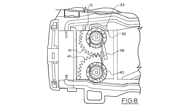
30 Figure 8 shows a detail view of the components of the cleat mechanism;
Figure 9 shows a detail view of the operation of the cleat mechanism;
Figure 10 shows a detail view of the electrical cord held in the cleat
mechanism;
Figure 11 is a view of the closing of the cover about an electrical cord;

CA 03039107 2019-04-01
WO 2018/064706 PCT/AU2017/000206
3
Figure 12 is a side section view of figure 11;
Figure 13 shows a detail view of the electrical cord held in the cleat
mechanism as
the cover is closed;
Figure 14 illustrates the forces applied to the cord of a closed cover
Figure 15 shows a side section view as the cover is closed;
Figure 16 is a cut away detail of the closed position;
Figure 17 illustrates the forces in the closed position.
The external appearance of the cover is shown in figures 1 to 6 and the opened
io cover is shown in figure 7.
The cover consists of a body part 10 and a lid 20 hinged by hinges 22 to the
body
10. When the cover is closed the clips 24 on lid 20 engage the ribs 13 on the
external surface of the body 10 to securely close the cover. A bracket 18 for
suspending the cover is located on the external surface of the body 10 and may
be
is extended as shown in figure 1 or retracted as shown in figure 2.
The socket and plug connected together are accommodated in the interior space
in
the central portion between the lid 20 and body 10. The electrical leads 50
extend
out of the cover through the apertures 26 formed between the ends15 of the
closed
body and ends 25 of the closed lid.
20 To prevent forced removal of the leads from the cover a restraint
mechanism is
located in the body portion adjacent each end 15. The restraint mechanism
consists
of a master cleat 30 and a slave cleat 40 each with intermeshing gears 31, 41.
The
master cleat can be turned by the lever 34 and the spring 36 applies tension
to the
master cleat 30. As shown in figures10, 13 and 14, the electrical lead 50
passes
25 between the master 30 and slave cleat 40 and is gripped between them.
The master cleat 30 carries a flexible arm 32 with its barb 33 that engages
the post
12 of body 10.as shown in figures 8 and 9 the movement of the lever 34 moves
the
flexible arm 32 past post 12, so that the barb 33 abuts post 12 to latch the
restraint
to allow the lead to be placed between the master cleat 30 and slave cleat 40
and in
30 the half of aperture 26 in ends 15 of the body. When the lid 20 is
closed the
cammed surface 27 on the internal surface of lid 20 pushes the barb 33 away
from
post 12 so that the spring acts to rotate the master cleat 30 and slave cleat
40 to
engage the surface of the lead 50 as shown in figures 13, 14 and 15.

CA 03039107 2019-04-01
WO 2018/064706 PCT/AU2017/000206
4
The mechanism releases the cleats automatically when the lid is closed. The
cleats
have to latch during use, otherwise it would be very awkward to insert the
lead with
two pairs of cleats. The mechanism uses no extra parts to achieve this.
The outward force 52 on the cleat is shared between post and upper housing to
resist very high loads as illustrated in figure 17.
The cleats 30 and 40 are mounted equidistant from axis of force (the
electrical lead
50 that is to be retained) on two plastic bosses. The cleats 30 and 40 are
positioned
up from the base of the bosses to allow room for the spring 36 which creates
the
pre-tension. As shown in figure 17 this distance may create an issue as these
io bosses may have a longer lever arm, allowing them to bend under force
53. To
counteract this the cleats are additionally supported higher up by bearing
points 54
in the upper housing when under load. Some or all of the force acting on the
cleat is
shared with the enclosure. This keeps them in position under a much higher
force
than if they were only supported by the bosses.
is The cleats 30 and 40 are geared together, so opening one also opens the
other.
This also keeps the lead 50 centralised, as it has to be positioned in the
centre of
the aperture 26 seal for this to work.
There is a web 29 on the lid that fills up the space between the cleats 30 and
40
when closed, to stop the lead potentially riding up on the cleats under high
forces.
20 The cleats are injection moulded so the teeth aren't parallel, but
camber outwards to
the opening on top.
Those skilled in the art will realise that this invention provides a unique,
convenient
and cost effective solution to the provision of a water tight cover for
electrical plugs
and sockets
25 Those skilled in the art will also realise that this invention can be
implemented in
embodiments other than that described without departing from the core
teachings of
the invention.

Representative Drawing
A single figure which represents the drawing illustrating the invention.
Administrative Status

For a clearer understanding of the status of the application/patent presented on this page, the site Disclaimer , as well as the definitions for Patent , Administrative Status , Maintenance Fee  and Payment History  should be consulted.

Administrative Status

Title Date
Forecasted Issue Date Unavailable
(86) PCT Filing Date 2017-10-03
(87) PCT Publication Date 2018-04-12
(85) National Entry 2019-04-01
Examination Requested 2022-12-15

Abandonment History

There is no abandonment history.

Maintenance Fee

Last Payment of $210.51 was received on 2023-09-25


 Upcoming maintenance fee amounts

Description Date Amount
Next Payment if small entity fee 2024-10-03 $100.00
Next Payment if standard fee 2024-10-03 $277.00

Note : If the full payment has not been received on or before the date indicated, a further fee may be required which may be one of the following

  • the reinstatement fee;
  • the late payment fee; or
  • additional fee to reverse deemed expiry.

Patent fees are adjusted on the 1st of January every year. The amounts above are the current amounts if received by December 31 of the current year.
Please refer to the CIPO Patent Fees web page to see all current fee amounts.

Payment History

Fee Type Anniversary Year Due Date Amount Paid Paid Date
Application Fee $400.00 2019-04-01
Maintenance Fee - Application - New Act 2 2019-10-03 $100.00 2019-09-20
Maintenance Fee - Application - New Act 3 2020-10-05 $100.00 2020-09-10
Maintenance Fee - Application - New Act 4 2021-10-04 $100.00 2021-08-20
Maintenance Fee - Application - New Act 5 2022-10-03 $203.59 2022-09-26
Request for Examination 2022-10-03 $816.00 2022-12-15
Late Fee for failure to pay Request for Examination new rule 2022-12-15 $150.00 2022-12-15
Maintenance Fee - Application - New Act 6 2023-10-03 $210.51 2023-09-25
Owners on Record

Note: Records showing the ownership history in alphabetical order.

Current Owners on Record
AMPFIBIAN HOLDINGS PTY LTD
Past Owners on Record
None
Past Owners that do not appear in the "Owners on Record" listing will appear in other documentation within the application.
Documents

To view selected files, please enter reCAPTCHA code :


To view images, click a link in the Document Description column. To download the documents, select one or more checkboxes in the first column and then click the "Download Selected in PDF format (Zip Archive)" or the "Download Selected as Single PDF" button.

List of published and non-published patent-specific documents on the CPD .

If you have any difficulty accessing content, you can call the Client Service Centre at 1-866-997-1936 or send them an e-mail at CIPO Client Service Centre.


Document
Description 
Date
(yyyy-mm-dd) 
Number of pages   Size of Image (KB) 
RFE Fee + Late Fee 2022-12-15 3 75
Abstract 2019-04-01 2 74
Claims 2019-04-01 2 56
Drawings 2019-04-01 14 373
Description 2019-04-01 4 202
Representative Drawing 2019-04-01 1 24
International Search Report 2019-04-01 3 82
National Entry Request 2019-04-01 3 81
Cover Page 2019-04-16 2 54
Examiner Requisition 2024-04-30 3 168