Note: Descriptions are shown in the official language in which they were submitted.
t5185881
A
DtSCRIPTION
Image Information Encoding and Decoding Method
This application is a divisional application of Canadian Patent
= Application No. 2,982,695, filed October 17, 2017, which is a
divisional application of Canadian Patent Application No,
2840476 filed December 16, 2011.
Technical Field
=
[0001] The present invention relates to an image compression
technique, and dote particularly, to a method of applying a sample
adaPtive offset (SAO) as an in-loop filter.
=
Background Art
[0002] in recent years, demands for a high-resolution and
high-quality video have increased in various fields of applications.
As a video has a higher resolution and higher quality, an amount of
data on the video increases more and more. Accordingly, when video .
data is transferred using media such as existing wired or wireless
broadband lines. or video data is stored in existing storage media,
. ,
the transfer cost and the storage cost of data increase.
[0003] In order to effectively, transfer, store, and reproduce
information on high-resolution and high-quality video, high-
efficiency video compression techniques can be utilized.
[0004] In order to enhance video compression efficiency, inter .
=
= prediction and intra prediction can be utilized. In the inter
=
,prediction method, pixel values of a current picture are predicted
with reference to information of another picture. In the intra
prediction method, pixeLvalues'of a current picture are predicted
using inter-pixel relationships in the same picture.
Summary of the Invention =
= Technical Problem
30. [0005] An object of the invention is to provide a method
of
L
=
.!
=
CA 3039403 2019-04-08
85185881
adaptively applying an SAO to improve an picture reconstruction
effect.
[0006] Another object of the invention is to provide a method
of applying an SAO in consideration of an occurrence frequency of
a pixel by intensity.
[0007] Still another object of the invention is to provide a
method of transmitting information for applying an SAO to only an
effective band from an encoder to a decoder.
[0008] Still another object of the invention is to provide a
method of applying plural SAOs depending on an SAO application
unit.
[0009] Still another object of the invention is to provide a
method and a device for applying an SAO on chroma pixels so as to
enhance a shape reconstruction effect.
[0010] Still another object of the invention is to provide a
method of applying an SAO in consideration of characteristics of
chroma pixels.
Solution to Problem
[0010a] An aspect of the present disclosure relates to a video
decoding method by a decoding apparatus, the method comprising:
obtaining video information including prediction information and
offset information; performing prediction to derive a predicted
block based on the prediction information; generating a
reconstructed picture based on the predicted block; and
performing a sample adaptive offset process on at least one of a
luma sample or a chroma sample of the reconstructed picture,
2
CA 3039403 2019-04-08
85185881
wherein the offset information includes first flag information
indicating whether the sample adaptive offset process is enabled
to the luma sample and second flag information indicating whether
the sample adaptive offset process is enabled to the chroma
sample, and wherein the offset information includes start band
information indicating one of 32 bands as a starting band of a
band group consisting of n bands among the 32 bands, the band
group is determined based on the starting band, and an offset
corresponding to a band among the n bands is applied to the luma
sample or the chroma sample, wherein n is a positive integer.
[0010b] An aspect of the present disclosure relates to a video
encoding method by an encoding apparatus, the method comprising:
deriving a prediction block based on inter prediction or intra
prediction; generating a reconstructed picture based on the
predicted block; performing a sample adaptive offset process on
at least one of a luma sample or a chroma sample of the
reconstructed picture; and encoding video information including
prediction information on the predicted block and offset
information for the sample adaptive offset process, wherein the
offset information includes first flag information indicating
whether the sample adaptive offset process is enabled to the luma
sample and second flag information indicating whether the sample
adaptive offset process is enabled to the chroma sample, and
wherein the offset information includes start band information
indicating one of 32 bands as a starting band of a band group
consisting of n bands among the 32 bands, the band group is
determined based on the starting band, and an offset
corresponding to a band among the n bands is applied to the luma
sample or the chroma sample, wherein n is a positive integer.
2a
CA 3039403 2019-04-08
85185881
[0010c] An aspect of the present disclosure relates to a non-
transitory computer-readable storage medium storing a bitstream
generated by performing: deriving a prediction block based on
inter prediction or intra prediction; generating a reconstructed
picture based on the predicted block; performing a sample adaptive
offset process on at least one of a luma sample or a chroma sample
of the reconstructed picture; and encoding video information
including prediction information on the predicted block and offset
information for the sample adaptive offset process, wherein the
offset information includes first flag information indicating
whether the sample adaptive offset process is enabled to the luma
sample and second flag information indicating whether the sample
adaptive offset process is enabled to the chroma sample, and
wherein the offset information includes start band information
indicating one of 32 bands as a starting band of a band group
consisting of n bands among the 32 bands, the band group is
determined based on the starting band, and an offset corresponding
to a band among the n bands is applied to the luma sample or the
chroma sample, wherein n is a positive integer.
[0011] (1) According to an aspect of the invention, there is
provided a video information encoding method including the steps
of: generating a reconstructed block; applying a deblocking
filter to the reconstructed block; applying a sample adaptive
offset (SAO) to the reconstructed block to which the deblocking
filter has been applied; and transmitting information on the
application of the SAO, wherein the step of applying the SAO
includes adaptively applying the SAO depending on an SAO
application region to which the SAO will be applied.
[0012] (2) In the video information encoding method according
to (1), the step of applying the SAO may include dividing an
2b
CA 3039403 2019-04-08
intensity section having a high occurrence frequency into bands of
a finer intensity unit and applying a band offset.
[0013] (3) Tn the video information encoding method according
to (1), the step of applying the SAO may include applying a band
offset to an intensity section having a high occurrence frequency,
and the step of transmitting information may include transmitting
information on a section to which the band offset is applied.
[0014] (4) In the video information encoding method according
to (1), the step of applying the SAO may include applying an offset
to only a band having a high occurrence frequency, and the step of
transmitting information may include transmitting information on
the applied offset.
[0015] (5) In the video information encoding method according
to (1), the step of applying the SAO may include selectively
applying a plurality of different edge offsets to pixels of one SAO
application region.
00167 (6) According to another aspect of the invention, there
is provided a video information encoding method including the steps
of: generating a reconstructed block; applying a deblocking filter
to the reconstructed block; applying a sample adaptive offset (SAO)
to the reconstructed block to which the deblocking filter has been
applied; and transmitting information on the application of the SAO,
wherein the step of applying the SAO includes applying the SAO to
chrome pixels, and wherein the step of transmitting information
includes transmitting at least one of region information, division
information of an SAO application region, SAO type information, and
SAO offset information along with information on whether to apply
the SAC to the chroma pixels.
[0017) (7) In the video information encoding method according
to (6), the step of applying the SAO may include setting an SAO
3
CA 3039403 2019-04-08
application region for chroma independently of an SAO application
region for luma.
[0016] (8) In the video information encoding method according
to (6), the step of applying the SAO may include classifying
intensities of chroma pixels and applying a band offset to a band
located in a section of a high occurrence frequency in the entire
intensity range.
[0019] (9) In the video information encoding method according
to (6), the step of applying the SAO may include determining to
which of a case where the intensity of at least one of neighboring
chrome pixels is greater than the intensity of a current pixel and
a case where the intensity of at least one of neighboring chrome
pixels is less than the intensity of the current chrama pixel a
relationship between the current chroma pixel and the neighboring
chrome pixels belongs and applying an edge offset to the current
chrome pixel depending on the determination result.
[0020] (10) In the video information encoding method according
to (6), the step of transmitting information may include separately
transmitting the SAO information for luma and chrome.
[0021] (11) According to still another aspect of the invention,
there is provided a video information decoding method including the
steps of: receiving information; generating a reconstructed block
on the basis of the received information; applying a deblocking
filter to the reconstructed block; and applying a sample adaptive
offset (SAO) to the reconstructed block to which the deblocking
filter has been applied, wherein the step of applying the SAO
includes adaptively applying the SAO depending on an SAO
application region to which the SAO will be applied.
[0022] (12) In the video information decoding method according
to (11), the step of applying the SAO may include dividing an
4
CA 3039403 2019-04-08
intensity section having a high occurrence frequency into bands of
a finer intensity, unit and applying a band offset.
[0023] (13) In the
video information decoding method according
to (11), the step of applying the SAO may include applying a band
offset to an intensity section having a high occurrence frequency,
and the intensity section having a high occurrence frequency may be
determined on the basis of the received information.
[0024]. (14) In the
video information decoding method according
to (11), the step of applying the SAO may include applying an
offset to only a band corresponding to the offset included in the
received information out of the total bands.
[0025] (15) In the
video information decoding method according
to (11), the step of applying the SAO may include selectively
applying a plurality of different edge offsets to pixels of one SAO
application region, and the selectively-applied edge offsets may be
determined on the basis of the received information.
[0026] (16) According
to still another aspect of the invention,
there is provided a video information decoding method including the
steps of: receiving information; generating a reconstructed block;
applying a deblocking filter to the reconstructed block; and
applying a sample adaptive offset (SAO) to the reconstructed block
to which the deblocking filter has been applied, wherein the step
of applying the SAO includes applying the SAO to chroma pixels, and
wherein the information received in the step of receiving
information includes at least one of region information, division
information of an SAO application region, SAO type information, and
SAO offset information along with information on whether to apply
the SAO to the chroma pixels.
[0027] (17) In the
video information decoding method according
to (16), an SAO application region for chrome in the step of
5
CA 3039403 2019-04-08
applying the SAO may be set independently of an SAO application
region for luma.
[0028] (18)
In the video information decoding method according
to (16), the step of applying the SAO may include classifying
intensities of chrome pixels and applying a band offset to a band
located in a section of a high occurrence frequency in the entire
intensity range.
[0029] (19)
In the video information decoding method according
to (16), the step of applying the SAO may include determining to
which of a case where the intensity of at least one of neighboring
chroma pixels is greater than the intensity of a current pixel and
a case where the intensity of at least one of neighboring chroma
pixels is less than the intensity of the current chroma pixel a
relationship between the current chroma pixel and the neighboring
=
chrome pixels belongs and applying an edge offset to the current
chrome pixel depending on the determination result, and the value
of the edge offset may be determined on the basis of the
information received in the step of receiving information.
[0030] (20)
In the video information decoding method according
to (16), the information received in the step of receiving
information may indicate which of information on luma, information
on chroma, and information on both luma and chrome the information
is.
Advantageous Effects
[0031]
According to the invention, it is possible to enhance a
video. reconstruction effect by adaptively applying an SAO.
[0032]
According to the invention, it is possible to enhance a
video reconstruction effect by applying an SAO in consideration of
an occurrence frequency of a pixel by intensity.
6
CA 3039403 2019-04-08
[0033] According to the invention, it is possible to reduce an
amount of information to be transmitted by applying an SAO to only
an effective band and transmitting relevant information from an
encoder to a decoder.
[0034] According to the invention, it is possible to enhance a
picture reconstruction effect by applying plural SAOs depending on
an SAO application unit.
[0035] According to the invention, it is possible to enhance a
picture reconstruction effect by applying an SAO on chroma pixels.
[0036] According to the invention, it is possible to enhance a
picture reconstruction effect by applying an SAO to chroma pixels
in consideration of characteristics of the chroma pixels.
Brief Description of the Drawings
[0037] FIG. 1 is a block diagram schematically illustrating a
video encoding apparatus (encoder) according to an embodiment of
the invention.
[0038] FIG. 2 is a block diagram schematically illustrating a
video decoder according to an embodiment of the invention.
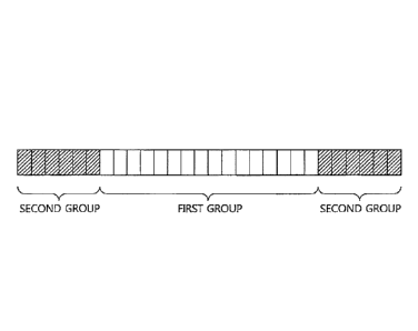
[0039] FIG. 3 is a diagram schematically illustrating a band
offset.
[0040] FIG. 4 is a diagram illustrating an example of
histograms based on characteristics of a predetermined picture.
[0041] FIG. 5 is a diagram schematically illustrating an
example of a method of adaptively dividing intensities of all
pixels and applying a band offset thereto.
[0042) FIG. 6 is a diagram schematically illustrating another
example of the method of adaptively dividing intensities of all
pixels and applying a band offset thereto.
[0043] FIG. 7 is a diagram illustrating examples of
7
CA 3039403 2019-04-08
-representative forms of edges which can occur in a block by
directions.
[0044] FIG. B is a diagram illustrating four representative
edge types of an edge offset with respect to a current pixel (C).
'5 [0045] FIG. 9 is, a diagram schematically illustrating an
example where a current pixel is compared in intensity with
neighboring pixels arid the intensities are grouped into four
categories.
[0046] FIG. 10 is a diagram schematically illustrating an SAO
.10 application unit as a-region to which an SAO is applied.
[0047] FIG. 11 is a diagram illustrating local distributions
of a histogram of the same picture.
[0048] FIG. 12 is a diagram schematically illustrating an
example where a band offset is applied to only some bands of the
15 total bands for chrome pixels.
[0049] FIG. 13 is a diagram schematically illustrating another
example where the band offset is applied to only some bands of the
total bands for chrotha p1xe1s'
[0050] . FIG. 14 is a flowchart schematically illustrating an
20 operation of an encoder in a system according to the invention.
[0051] FIG. 15 is a flowchart schematically illustrating an
= operation of a decoder in a system according to the invention.
Description of Exemplary Embodiments
h 25 [0052] The invention may be variously modified in various
forms and may have various embodiments, and specific eMbodiments
thereof will be illustrated in the drawings and described in detail.
However, these embodiments are not intended for limiting the
invention. Terms used in the below description are used to merely
30 describe specific embodiments,
,
=
CA 3039403 2019-04-08
An expression of a singular
number includes an expression of a plural number, so long as it is
clearly read differently. Terms such as "include" and "have" in
this description are intended for indicating that features, numbers,
steps, operations, elements, components, or combinations thereof
used in the below description exist, and it should be thus
understood that the possibility of existence or addition of one or
more different features, numbers, steps, operations, elements, .
components, or combinations thereof is not excluded.
[0053] On the other hand, elements of the drawings described
In the invention are independently drawn for the purpose of
convenience of explanation on different specific functions in a
video encoder and a video decoder, and do not mean that the '
elements are embodied by independent hardware or independent
software. For example, two or more elements out of the elements
may be combined to form a single element, or one element may be
divided into plural elements. Embodiments in which the elements
are combined and/or divided belong to the scope of the invention
without departing from the concept of the invention.
' [0054) Hereinafter, exemplary embodiments of the invention
will be described in detail with reference to the accompanying
drawings. The same elements in the drawings will be referenced by
the same reference signs and the description of the same elements
will not be repeated.'
[0055) FIG. 1 is a block diagram schematically illustrating a
video encoding apparatus (encoders according to an embodiment of
the invention. Referring to FIG. 1, a video encoder 100 includes a
picture dividing module 105, a prediction module 110, a transform
module 115, a quantization module 120, a rearrangement module 125,
an entropy encoding. module 130, a dequantization module 135, an
9
=
CA 3039403 2019-04-08
inverse transform module 140, a filter module 145, and a memory 150.
[0056] The picture dividing module 105 can divide an input
picture into at least one process unit. Here, the process unit may
be a prediction unit (hereinafter, referred to as a "PU"), a
transform unit (hereinafter, referred to as a "TU-), or a coding
unit (hereinafter, referred to as a "CU").
[0057] The prediction module 110 includes an inter prediction
module that performs an inter prediction process and an intra
prediction module that performs an intra prediction process, as
will be described later. The prediction module 110 predicts the
process unit of the picture divided by the picture dividing module
105 to generate a prediction block. The process unit of a picture
in the prediction module 110 may be a CU, a TU, or a PU. It may be
determined whether the prediction performed on the corresponding
process unit is inter prediction or intra prediction, and specific
details (for example, a prediction mode) of the prediction methods
may be determined. The process unit subjected to the prediction
process may be different from the process unit of which the
prediction method and the specific details are determined. For
example, the prediction method and the prediction mode may be
determined by the PU units and the prediction process may be
performed by the TU units.
[0058] In the inter prediction, a prediction process is
performed on the basis of information on at least one of a previous
picture and/or a subsequent picture of a current picture to
generate a prediction block. In the intra prediction, a prediction
process is performed on the basis of pixel information of a current
picture to generate a prediction block.
[0059] In the inter prediction, a reference picture is
selected for a PU, and a reference block having the same size as
LO
CA 3039403 2019-04-08
the PU is selected. Then, a prediction block is generated so that
a residual signal from the current PU is minimized and the
magnitude of a motion vector is minimized. On the other hand, a
skip mode, a merge mode, an MVP (Motion Vector Prediction), or the
like can be used as the intra prediction method. The prediction
block may be generated in the unit of pixel samples less than an
integer pixel, such as 1/2 pixel samples and 1/4 pixel samples.
Here, a motion vector can also be expressed in the unit of pixel
samples less than an integer pixel. For example, luma pixels can
be expressed in the unit of 1/4 pixels and Chrome pixels can be
expressed in the unit of 1/8 pixels.
[0060] Information such as an index of a reference picture
selected through the inter prediction, a motion vector (for example,
a motion vector predictor), and a residual signal is entropy
encoded and is transmitted to a decoder.
[0061] When the intra prediction is performed, a prediction
mode may be determined in the unit of PUs and the prediction
process may be performed in the unit of PUs. Alternatively, a
prediction mode may be determined in the unit of PCs and the inter
prediction may be performed in the unit of TUs.
[0062] The prediction modes in the intra prediction include 33
directional prediction modes and at least two non-directional modes.
The non-directional modes include a DC prediction mode and a planar
mode.
[0063] In the intra prediction, a prediction block may be
generated after a filter is applied to reference samples. At this
time, it may be determined whether a filter should be applied to
reference samples, depending on the intra prediction mode and/or
the size of a current block.
[0064] A PU may have various sizes/shapes. For example, in
11
=
CA 3039403 2019-04-08
case of the inter prediction, a PU may have sizes such as 2Nx2N,
2NxN, Nx2N, and NxN. In case of the intra prediction, a PU may
have sizes such as 2Nx2N and NxN (where lc is an integer). The PU
having a size of NxN may be set to be used in only a specific case.
For example, the PU having a size of NxN may be set to be used for
only a coding unit having the smallest size or may be set to be
used for only the intra prediction. In bddition to the Pt-Is having
the above-mentioned sizes, PUs having sizes such as NxmN, mNxN,
2NxmN, and oNx2N (where m<l) may be additionally defined and used.
[0065] Residual values (a residual block or a residual signal)
between the generated prediction block and the original block are
input to the transform module 115. The prediction mode information,
the motion vector information, and the like used for the prediction
are encoded along with the residual values by the entropy encoding
module 130 and are transmitted to the decoder.
[0066] The transform module 115 performs a transform process =
on the residual block by transform units and generates transform
coefficients. The transform unit in the transform module 115 may
be a TU and may have a quad tree structure. The size of the
transform unit may be determined within a predetermined range of
largest and smallest sizes. The transform module 115 may transform
the residual block using a DCT (Discrete Cosine Transform) and/or a
DST (Discrete Sine Transform).
[0067] The quantization module 120 may quantize the residual
values transformed by the transform module 115 and may generate
quantization coefficients. The values calculated by the
quantization module 120 may be supplied to the dequantization
module 135 and the rearrangement module 125.
[0068] The rearrangement module 125 may rearrange the
quantization coefficients supplied from the quantization module 120.
12
CA 3039403 2019-04-08
By rearranging the quantization coefficients, it is possible to
enhance the coding efficiency in the entropy encoding Module 130.
The rearrangement module 125 may rearrange the quantization
coefficients in the form of a two-dimensional block to the form of
a one-dimensional vector through the use of a coefficient scanning
method. The rearrangement module 125 may enhance the entropy
encoding efficiency in the entropy encoding module 130 by Changing
the order of coefficient scanning on the basis of stochastic
statistics of the coefficients transmitted from the quantization
module.
[0069] The entropy encoding module 130 may perform an entropy
encoding process on the quantization coefficients rearranged by the
rearrangement module 125. Examples of the entropy encoding method
include an exponential golomb method, a CAVLC (Context-Adaptive
Variable Length Coding) method, and a CABAC (Context-Adaptive
Binary Arithmetic Coding) method. The entropy encoding module 130
may encode a variety of information such as quantization
coefficient information and block type information of a coding unit,
prediction mode information, division unit information, PU
information, transfer unit information, motion vector information,
reference picture information, block interpolation information, and
filtering information transmitted from the rearrangement module 125
and the prediction module 110.
[0070] The entropy encoding module 130 may give a
predetermined change to a parameter set or syntax to be transmitted,
if necessary.
[0071] The dequantization module 135 dequantizes the values
quantized by the quantization module 120. The inverse transform
module 140 inversely transforms the values dequantized by the
dequantization module 135. The residual values generated by the
13
=
CA 3039403 2019-04-08
dequantization module 135 and the inverse transform module 140 may
be merged with the prediction block predicted by the prediction
module 110 to generate a reconstructed block.
[0072] The filter Module 145 applies a deblocking filter, an
ALF (Adaptive Loop Filter), an SAO (Sample Adaptive Offset) to the
reconstructed picture.
[0073] The deblocking filter remove a block distortion
generated at the boundary between blocks in the reconstructed
picture. The ALF performs a filtering process on the basis of the
resultant values of comparison of the original picture with the
reconstructed picture of which the blocks have been filtered by the
deblocking filter. The ALF may be applied only when high
efficiency is necessary. The SAO reconstructs offset differences
between the residual blocks having the deblocking filter applied
thereto and the original picture by pixels and is applied in the
form of a band offset, an edge offset, or the like.
[0074] On the other hand, the filter module 145 may not
perform a filtering process on the reconstructed block used for the
inter prediction.
[0075] The memory 150 stores the reconstructed block or
picture calculated by the filter module 145. The reconstructed
block or picture stored in the memory 150 is supplied to the
prediction module 110 that performs the inter prediction.
[0076]
[0077] FIG. 2 is a block diagram schematically illustrating a
video decoder according to an embodiment of the invention.
Referring to FIG. 2, a video decoder 200 includes an entropy
decoding module 210, a rearrangement module 215, a daquantization
module 220, an inverse transform module 225, a prediction module
230, a filter module 235, and a memory 240.
14
=
CA 3039403 2019-04-08
[0078] When a video bitstream is input from the video encoder,
the input bitstream is decoded on the basis of the order in which
video information is processed by the video encoder.
[0079] For example, when the video encoder uses a variable
length coding (hereinafter, referred to as "VIC") method such as
the CAVIC method to perform the entropy encoding process, the
entropy decoding module 210 may implement the same VIC table as the
VIC table used in the video encoder and may perform the entropy
decoding process. When the video encoder uses the CABAC method to
perform the entropy encoding process, the entropy decoding module
210 may perform the entropy decoding process using the CABAC method
to correspond thereto.
[0080] Information for generating a prediction block out of
the information decoded by the entropy decoding module 210 is
supplied to the prediction module 230, and the residual values
entropy-decoded by the entropy decoding module are input to the
rearrangement module 215.
[0081] The rearrangement module 215 rearranges the bitstream
entropy-decoded by the entropy decoding module 210 on the basis of
the rearrangement method in the video encoder. The rearrangement
module 215 reconstructs and rearranges coefficients expressed in
the form of a one-dimensional vector into coefficients in the form
of a two-dimensional block. The rearrangement module 215 may be
supplied with information associated with the coefficient scanning
performed by the encoder and may perform the rearrangement using a
method of inversely scanning the coefficients on the basis of the
scanning order in which the scanning is performed by the encoder.
[0082] The dequantization module 220 may perform =
dequantization on the basis of the quantization parameters supplied
from the encoder and the coefficient values of the rearranged block.
CA 3039403 2019-04-08
[0083] The inverse transform module 225 may perform the
inverse OCT and/or inverse DST of the DCT and DST, which has been
performed by the transform module of the encoder, on the
quantization result from the video encoder. The inverse transform
may be performed on the basis of a transfer unit or a division unit
of a picture determined by the encoder. The transform module of
the encoder may selectively perform the DCT and/or DST depending on
plural information pieces such as the prediction method, the size
of a current block, and the prediction direction, and the inverse
transform module 225 of the decoder may perform the inverse
transform on the basis of the transform information on the
transform performed by the transform module of the encoder.
[0084] The prediction module 230 may generate a prediction
block on the basis of prediction block generation information
supplied from the entropy decoding module 210 and the previously
decoded block and/or picture information supplied from the memory
240. The reconstructed block may be generated using the prediction
block generated by the prediction module 230 and the residual block
supplied from the inverse transform module 225. When the
prediction mode of a current PU is an intra prediction mode, an
intra prediction process of generating a prediction block on the
basis of pixel information of a current picture may be performed.
[0085) When the prediction mode for a current block is the
= inter prediction mode, the inter prediction process on the current
PU may be performed on the basis of information included in at
least one of a previous picture and a subsequent picture of the
current picture is used as a reference picture. At this time,
motion information necessary for the inter prediction of the
current PU, for example, information on motion vectors, reference
picture indices, and the like, can be derived from a skip flag, a
16
CA 3039403 2019-04-08
merge flag, and the like received from the encoder.
[0086] The reconstructed block and/or picture may be supplied
to the filter module 235. The filter module 235 performs a
deblocking filtering process, an SAO (Sample Adaptive Offset)
process, and/or an adaptive loop filtering process on the
reconstructed block and/or picture.
[0087] The memory 240 may store the reconstructed picture or
block for use as a reference picture or a reference block and may
supply the reconstructed picture to an output module.
[0088]
[0089] On the other hand, the filter modules of the encoder
and the decoder may apply the deblocking filter, the SAO (Sample
Adaptive Offset), and the ALF (Adaptive Loop Filter) as an in-loop
filter, as described above.
[0090) The deblocking filter removes artifacts between blocks
due to prediction, transform, and quantization in the unit of
blocks. The deblocking filter is applied to a prediction unit edge
or a transform unit edge and may set a predetermined smallest block
size for application of the deblocking filter.
[0091] A boundary strength (BS) of a horizontal or vertical
filter boundary is first determined to apply the deblocking filter.
It is determined in the unit of blocks whether to perform a
filtering process on the basis of the BS. When it is determined
that the filtering process should be performed, a filter to be
applied is determined. The filter to be applied may be selected
from weak filters and strong filters. The filtering module applies
the selected filter to the boundary of the corresponding block.
[0092] The SAO is a process of reconstructing an offset
difference between a picture subjected to the deblOCking filtering
30, process and the original picture in the unit of pixels. The SAO
17
CA 3039403 2019-04-08
_ =
serves to compensate for a coding error. Here, the coding error
may be based on quantization or the like.
[0093] As described above, the SAO is classified into two
types of a band offset and an edge offset.
[0094] FIG. 3 is a diagram schematically illustrating the band
offset.
[0095] In order to apply the band offset, pixels in an SAO
application unit are classified depending on intensities of the
pixels. The entire intensity range may be divided into a
predetermined number of intensity intervals, that is, bands. Each
band includes pixels having intensities in the corresponding
intensity interval. The offset to be applied may be determined for
each band.
[0096] In case of a picture including N -bit pixels, the number
of intensity intervals ranges from 0 to 2'4-1. For example, 8-bit
pixels are classified into 0 to 255 intensity intervals. FIG. 3
illustrates an example where the entire intensity range is divided
into 32 bands having the same intensity gap.
[0097] Referring to FIG. 3, the intensity intervals of the
bands are 8. The 32 bands may be divided into a first group at the
center and a second group neighboring the first group. The first
group includes 16 bands and the second group includes 16 bands.
The offset may be applied to each band and the offset value for
each hand may be applied to the decoder.
. 25 [0098] In the decoder, pixels are grouped and the offset value
transmitted for each band is applied to the groups.
[0099] The ALF compensates for a coding error using a Wiener
filter. The ALF is globally applied to a slice unlike the SAO. The
ALF may be applied after the SAO is applied, or may be applied only
when HE (High Efficiency) is necessary. Information (such as .a
18
=
CA 3039403 2019-04-08
filter coefficient, ON/OFF information, and a filter shape) for
applying the ALF may be transmitted to the decoder through the use
of a slice header. Various shapes such as a two-dimensional
diamond shape and a two-dimensional cross shape may be used as the
shape of the filter used for the ALF-
[0100] On the other hand, it may be considered that the SAO is
adaptively applied depending on the region to which the SAO is
applied, that is, the SAO application unit. Hereinafter, a method
of performing an adaptive SAO in the system according to the
invention will be described by the band offset and the edge offset.
[0101]
[0102] <AdaptiVe Application of Band Offset>
[0103] FIG. 4 is a diagram illustrating an example of
histograms based on characteristics of a predetermined picture.
Specifically, FIG. 4 illustrates histograms based on luma
characteristics as in FIG. 11(b).
[0104] Referring to FIG. 4, it can be seen that a histogram
has various distributions depending on the characteristics of a
picture. Therefore, a pixel range may be adaptively divided and
the band offset may be applied thereto. That is, a method of
adaptively setting bands of an intensity range of pixels and
applying an offset may be considered.
[0105] For example, when histograms of a picture of a
corresponding block are concentrated on the central part in the
entire intensity range, a method of dividing the central part more
densely to set the bands and dividing the side parts less densely
to set the bands may be considered. Specifically, when pixels of N
bits are concentrated on the central part in the entire intensity
range (0 to 2N-1), M bands having small intensity intervals may be
19
CA 3039403 2019-04-08
set in the central part and L bands having large intensity
intervals may be set in the side part.
[0106] On the contrary, when histograms of a picture of the
corresponding block are concentrated on the side parts in the
entire intensity range, a method of dividing the side parts more
densely to set the bands and dividing the central part less densely
to set the bands may be considered. Specifically, when pixels of N
bits are concentrated on the side parts in the entire intensity
range (0 to 24-1), M bands having small intensity intervals may be
set in the side parts and L bands having large intensity intervals
may be set in the central part.
[0107] FIG. 5 is a diagram schematically illustrating an
example of a method of adaptively dividing an intensity range of
the total pixels and applying the band offset thereto. FIG. 5
illustrates an example where pixels are concentrated on the central
part.
[0108] In the example illustrated in FIG. 5, when the pixel
value range, that is, the pixel intensity range have 256 (0 to 28-
1) pixel values, the first group in the central part may be densely
divided into 16 bands by 4 pixel values (for example, four
intensity intervals) and the second group in the side parts may be
roughly divided into 12 bands by 16 pixel values.
[0109] When histograms of the picture of the corresponding
block are concentrated on the side parts in the entire intensity
range, the first group in the central part is divided into 12 bands
by 16 pixel values and the second group in the side parts may be
divided into 16 bands by 4 pixel values.
[0110] On the other hand, a method of classifying the entire
intensity range into more band groups than two band groups
. 30 depending on the SAO application unit may be considered. By
CA 3039403 2019-04-08
classifying the entire intensity range into more bands groups and
applying the offset thereto, it is possible to'enhance an effect of
picture reconstruction. For example, the bands may be classified
into N groups instead of two groups and a finer offset may be
applied to some pixel value ranges.
[0111] FIG. 6 is a diagram schematically illustrating an
example of the method of adaptively dividing the entire intensity
range of all pixels and applying a band offset thereto.
[0112] FIG. 6 illustrates an example where the entire
intensity range is divided into bands, the bands are classified
into four groups, and the band offset is applied thereto. As
illustrated in FIG. 6, by dividing the entire intensity range into
more groups than two groups and transmitting offset information for
each group, it is possible to better reflect local characteristics
of a picture.
[0113] On the other hand, when the pixel value range covered
by each group, that is, the intensity section, is fixed at the time
of applying the band offset, relevant information is transmitted
even when the occurrence frequency of a specific band in the group
is small or the band offset value of the corresponding band is O.
Therefore, in order to prevent this problem, the encoder may
transmit the range of the band offset applied to a current picture.
For example, the encoder may transmit information on what bit depth
section, that is, what intensity section, in the current picture is
subjected to the band offset to the decoder.
[0114] When the offsets of a current picture mainly occur in a
specific pixel value (for example, intensity) range and a band
offset is applied to bands with uniform intervals, it is possible
to prevent transmission of unnecessary offset information or
performing of an unnecessary offset by designating a band in which
21
CA 3039403 2019-04-08
application of the band offset is started and a band in which
application of the band offset is ended.
[0115] When a pixel value (for example, intensity) range in
which an offset mainly occurs and to which a band offset should be
applied in a current picture ranges from 32 to 160 and the size of
each band in the pixel value (for example, intensity) range of 0 to
256 is 8, the encoder may transmit information such as band start
and band end indicating a band in whidh application of the band
offset is started and a band in which application of the band
offset is ended out of total 32 bands to the decoder. When
application of the band offset is started in the fourth band out of
the total bands and the application of the band offset is ended in
the twentieth band, information such as band_start=4 and
band_end=20 may be transmitted.
[0116] The occurrence frequency of a pixel value belonging to
each band, that is, the occurrence frequency of each band, may be
counted and the offset value of the band offset of only a band
having the occurrence frequency of the pixel value may be
transmitted.
0117] For example, when bands having high occurrence
frequencies out of 32 bands 0 to 31 are 0, 4, 5, 6, 7, 9, 12, 15,
= 19, 20, 23, and 25, the encoder may transmit offset values in the
band offset to be applied to only the bands having high occurrence
frequencies to the decoder and may not transmit offset values in
the band offset to be applied to the bands having low occurrence
frequencies.
[0118] In this case, the encoder may additionally transmit
information on what bands the offset values are applied to the
decoder.
22
CA 3039403 2019-04-08
[0119] As a second type of SAO, there is an edge offset.
considering edge information for each pixel. The edge offset is
. applied in consideration of an edge direction with respect to a
current pixel and intensities of the current pixel and neighboring
pixels.
[0120] FIG. 7 is a diagram illustrating examples of
representative forms of edges which can occur in a block by
directions. Referring to FIG. 7, FIGS. 7(a) to 7(d) illustrate an
edge having a direction of 0 degrees, an edge having a direction of
90 degrees, an edge having a direction of 135 degrees, and an edge
having a direction of 45 degrees, respectively. Therefore, four
types for a single filtering unit, that is, an SAO application unit
(of which the smallest unit is a LCU) may be used as the edge
offset depending on the angles or directions of the edges. For the
purpose of convenience of explanation, four edge types of the SAO
application unit illustrated in FIG. 7 are referred to as edge
types of the edge offset.
[0121] FIG. 8 is a diagram illustrating four representative
edge types of the edge offset with respect to a current pixel (C).
In FIG. 8, FIG. 8(a) illustrates an edge of 0 degrees in one
dimension, FIG. 8(b) illustrates an edge of 90 degrees in one
dimension, FIG. 8(c) illustrates an edge of 135 degrees in one
dimension, and FIG. 8(d) illustrates an edge of 45 degrees in one
dimension. Four edge types may be used depending on the edge types
of the four directions illustrated in FIG. G. An offset
corresponding to one of the four edge types may be applied to each
SAO application unit.
[0122] After the edge type is determined, the relationship
between a current pixel and neighboring pixels may be considered to
apply an edge offset.
23
CA 3039403 2019-04-08
[0123] FIG. 9 is a diagram schematically illustrating an
example where a current pixel is compared in intensity with
neighboring pixels and the intensities are grouped into four
categories. Referring to FIG. 9, FIGS. 9(a) to 9(d) illustrate
distributions of a current pixel (C) and neighboring pixels for
each category. The category illustrated in FIG. 9(a) indicates a
case where intensities of two neighboring pixels are greater than
that of the current pixel (C). The category illustrated in FIG.
9(b) indicates a case where the intensity of one pixel of two
neighboring pixels of the current pixel is smaller than that of the
current pixel. The category illustrated in FIG. 9(c) indicates a
case where the intensity of one pixel of two neighboring pixels of
the current pixel is greater than that of the current pixel. The
category illustrated in FIG. 9(d) indicates a case where
intensities of two neighboring pixels of the current pixel are
greater than that of the current pixel.
[0124] For example,
FIGS. 9(a) and 9(b) illustrate cases where
the intensity of the current pixel is greater or smaller than those
of the neighboring pixels. FIGS. 9(b) and 9(d) may appear when the
current pixel is located at a boundary of a predetermined region.
[0125] Table 1
schematically shows four categories illustrated
in FIG. 9.
[0126] <Table 1>
(0127]
Category Condition
1 Intensity of
C<Intensities of two neighboring pixels
. 2 Intensity of C<Intensity
of one neighboring pixel and
intensity of Cr.-Intensity of one neighboring pixel
a Intensity of C>Intensity
of one neighboring pixel and
24
CA 3039403 2019-04-08
=
intensity of C=Intensity of one neighboring pixel
4 Intensity of C>Intensities of two neighboring pixels
0 No correspondence
[0128] In Table 1, C represents a current pixel. Category 1
in Table 1 corresponds to FIG. 9(a), Category 2 in Table 1
corresponds to FIG. 9(b), Category 3 in Table 1 corresponds to FIG.
9(c), and Category 4 in Table 1 corresponds to FIG. 9(d).
[0129] The encoder transmits an edge offset value for each
category. The decoder may add the edge offset value corresponding
to a category to the edge type of the pixels to reconstruct the
pixels. For example, after it is determined what of four edge
types illustrated in FIG. 7 the current pixel belongs to, the
category of the categories shown in Table 1 to which the current
pixel belongs may be determined and the offset of the corresponding
category may be applied to the current pixel.
[0130] On the other hand, filtering units, that is, SAO
application units, are units having a size equal to or larger than
the LCU (Largest Coding Unit) and are units aligned with the
boundary of the LCUs.
[0131] A unit to which the SAO is applied is a region obtained
by dividing one picture in a quad tree structure. The encoder may
determine whether to apply the SAO, the offset type, and the offset
values for each SAO application unit and may transmit the
determined information to the decoder. Here, determining of the
offset type means that which of plural band offsets and plural edge
offsets to apply is determined.
[0132] FIG. 10 is a diagram schematically illustrating the SAO
application units. FIG. 10 illustrates the SAO application units
obtained by dividing a WQVGA (416x240) picture in a quad tree
CA 3039403 2019-04-08
structure. Each. SAO application unit is larger than an LCU and may
be divided along the boundaries of the LCUs.
[0133] As described above, the smallest unit of the SAO
application unit is the LCU, but in case of a snail picture, the
size of the LCU may be an excessively large size to apply a single
offset thereto. For example, when the LCU has a size of 64x64, the
size of the LCU may be an excessively large size to reconstruct an
original picture using only a single offset. If two or more
different edges are present in a single LCU, two or more offsets
may be used for the single LCU.
[0134] When plural edge offsets are applied to a single SAO
= application unit, plural edges types out of FIGS. 8(a) to 8(d) may
be selected and applied depending on the directions of the edges in
the region.
[0135]
[0136] <SAO Syntax Structure>
[0137] Table 2 schematically shows an example of a sequence
parameter set syntax as a syntax structure for applying the SAO.
[0138] <Table 2>
[0139]
seq_parameter set_tsp( ) ( C Descriptor
sao used flag u(1)
[0140] Table 2 shows an example of information indicating
whether the SAO is applied to a current sequence. For example,
when the value of sac used flag in the syntax shown in Table 2 is 0,
it. means that the SAO cannot be used (disabled) for the current
sequence. When the value of sao_used flag is 1, it means that the
SAO can be used (enabled) for the current sequence.
26 =
CA 3039403 2019-04-08
[0141] Table 3 schematically shows an example of a slice
header syntax as a syntax structure for applying the SAO.
[0142] <Table 3>
[0143]
, slice header( ) ( C Descriptor
2
[0144] An SAO parameter (sao_parmn()) for applying the SAO may
be indicated by the slice header syntax shown in Table 3.
[0145] Table 4 schematically shows an example of an SAO
parameter syntax as a syntax structure for applying the SAO.
[0146] <Table 4>
[0147]
sao_pararn( ) ( C Descriptor
sao Jlag :2 u(1)lae(v)
if( sao_flag ) (
sao split_param( 0,0, 0 )
sao offselsaran( 0, 0, 0 )
)
[0148] when an SAO parameter is indicated using the slice
header syntax, parameters necessary for applying the SAO are
transmitted over the SAO parameter syntax. The parameters to be
transmitted include sao_split_parimn related to division of the SAO
application region and sao_offset_param related to an offset to be
applied in the SAO, as in the example shown in Table 4.
[0149] In the example shown in Table 4, when the value of
sao_flag is 1, it means that the SAO can be applied (enabled) to at
least a part of a current picture. When the value of sao flag is 0,
it means that the SAO cannot be applied (disabled) to the entire
current picture. Therefore, when the value of sec....flag is 1, the
SAO parameters may be indicated.
27
CA 3039403 2019-04-08
[0150] Table 5 schematically shows an example of a
sao_pplit_param related to division out of the SAO parameters as a
syntax structure for applying the SAO.
[0151] <Table 5>
[0152]
samplit_paxam( x, y, Depth ) [ C Descriptor
if(Depth < MaxSplitLevel )
split_flag[Depthj[y ]( x ) aospIitfiag 2 u(1)1ae(v)
. esa
split floe Depth if y ][ x ) =0
if( split flag[Depthi ][y j( x ] ) {
PT10...401klarmn(x+OiriqliDePth+1)
" Mao split_parmt0+4y40,Depth+1)
prposplit_parass(x+tla+1,Depttl+1)
ppo_splkpatwgx+4y+1,Depth+1)
1
}
[0153] In the example shown in Table 5, sao split_param(x, y,
=
Depth) indicates whether to additionally divide the SAO application
unit at the position designated by (x, y) and the depth designated
by "Depth". When the value of sao_pplit_param is 0, it means that
a current region is a leaf. Therefore, the current region is not
divided any more for application of the SAO. When the value of
sac_split_param is 1, it means that the current region can be
additionally divided into four child regions. When the SAO
application region is divided, division parameters (pqao_split-
param) for four divided regions may be indicated.
[0154] When sao_splitLparam(x, y, Depth) indicates that the
SAO application unit should be additionally divided, pqao_split-
param indicates whether to additionally divide the SAO application
unit for each divided region. In that whether to divide the SAO
application unit at the corresponding depth is indicated, the
syntax sao split_param may be used again for the divided regions
instead of the syntax pqao_split-param, where the depth of the
indicated region may be changed. For example, when the region of
28
CA 3039403 2019-04-08
which division will be indicated and the depth thereof are (x0, yO,
saoDepth) in indicating whether to divide a region for applying the
SAO and sao_split_param(x0, yO, saoDepth) indicates that the
corresponding region (x0, yO) should be divided, the depth may be
adjusted to "saoDepth+1" and whether to divide the divided regions
(x0+0, y0+0), (x0+0, y0+1), (x0+1, y0+0), and (x0+1, y0+1) may be
indicated again.
[0155] Table 6 schematically shows an example of a syntax
structure for applying sao_split_param to the divided regions again.
[0156] <Table 6>
[0157]
sao_offset_param( x0, yO, saoDepth) f
if( sao_split flad saoDepth ][ x0 ][ y0 ] ) (
sao_offset_param( x0 +0, y0 +0, saoDepth + 1)
sio_offset_param( x0 + 1, y0 + 0, saoDepth + 1)
sao_offset_param( x0 +0, y0 + 1, saoDepth + 1)
sao_offset_param( x0 + 1, y0 + 1, saoDepth 1)
) else {
sao_type_idx[ saoDepth ][ x0 ][ yo]
= if( sao_type idx[ saoDepth. ][ x0 ][ y0 ] 0 )
for( i = 0; i <NumSaoClass; i++)
sao_offset[ saoDepth ][ x0 1[ y0 ][ i
[0156] In Table 6, NumSaoClass indicates the number of SAO
categories or SAO offsets.
101593 Table 7 schematically shows an example of the syntax
sao_offset_param related to an offset out of the SAO parameters as
a syntax structure for applying the SAO.
[0160] <Table 7>
29
'
CA 3039403 2019-04-08
[0161]
sao offset_param ( a, y, Depth) ( C Descriptor
if( split flag[Depth ji x ) (
sao offsetparani ( x + 0, y + 0, Depth + 1 )
sao offset_param ( x + 1, y + 0, Depth+ )
sno offsetparam ( x + 0, y + 1 Depth + 1 )
sao offset_parant ( x + 1, y + 1, Depth+ 1 )
) else {
type_idx[ Depth ]( y )[ x sao_type_idx 2 ue(v)lae(v)
If( sao_type idx I= 0 ) (
if( sarttype idx > 4 ) { ioffsettypeisbandoffset
start offset
end offset
) else {
start offset= 0
end offset = PqaoOffsetNurn[saa type idx]
for( i stait offset i < end offset it4 )
offset[ Depth ][ y ]( x Jr ) = sao_offset 2 se(v)tae(v)
[0162] Referring to Table 7, when an SAO application region is
divided, the offset parameter may be indicated for each divided
region.
[0163] When an SAO application region is not divided any more,
the offset type of the corresponding SAO application region is
indicated.
[0164] In the example shown in Table 7, sad_type_index
indicates the offset type to be applied to the current region. The
number of SAO offsets or the number of SAO categories may be
determined depending on the offset type (sao type, sao_type_idx)
applied to the current region. An example of the syntax
information indicating the number of SAO offsets or the number of
SAO categories depending on the offset type is
PqaoOffsetNum[sao_type_idx] shown in Table 6.
[0165] In the example shown in Table 7, start_offset indicates
the smallest number of band offsets or edge offsets to be used. If
start offset is not available, it may be estimated that
CA 3039403 2019-04-08
start_offset has a value of 0. end_offset indicates the largest
number of band offsets or edge offsets to be used. When end_offset
is not available, the value of end_offset may be set to the number
of SAO categories (the number of offsets)
PqaoOffsetNum[sao_type_idx] determined depending on the SAO type
(sao_type_idx) as described above.
[0166] Table 8 schematically shows an example of an SAO offset
type. As described above with reference to Table 7, the number of
SAO category (the number of offsets) may be determined depending on
the offset type.
[0167] <Table 8>
[0168]
SAO type index Number of SAO . Edge type
sao_type_idx categories (reference)
0 0 non-applied
1 4 1D 0-degree edge
2 4 1D 90-degree edge
3 4 10 135-degree edge.
4 4 1D 45-degree edge
= 5 16 central band
6 16 side band
[0169] As shown in Table 8, the SAO type index may indicate
one of the edge offsets and the band offsets. Table 8 shows an
example where the total bands are divided into two groups and the
band offset is applied thereto. The SAO type index indicates one
of four edge offsets and two band offsets. The offset value is set
depending on the category of each SOA type. For example, in case
of the. edge offset, the offset value may be set for each edge type
31
=
CA 3039403 2019-04-08
by four categories corresponding to the intensities of the current
pixel and the neighboring pixels.
[0170] Table 9 schematically shows an example of the SAO
offset type when the band groups are adaptively divided and the
band offset is applied thereto.
[0171] <Table 9>
[0172]
SAO type index Number of SAO Edge type
(sao_type_idx) categories (reference)
0 0 non-applied
1 4 1D 0-degree edge
2 4 1D 90-degree edge
3 4 1D 135-degree edge
4 4 1D 45-degree edge
5 16 central band
6 12 side band
[0173] In the example shown in Table 9, the number of
categnries varies in the central bands and the side bands. For
example, in case of 256 pixels, the central band group and the side
band group each including 16 bands by 8 pixel values are
constructed in Table 8, but the central band group including 16
bands by 4 pixel values and the side band group including 12 bands
by 15 pixel values are used to apply the band offset in Table 9.
Therefore, the offset may be more densely applied to the central
bands.
[0174] Table 10 schematically shows another example of the SAO
offset type when the band groups are adaptively divided and the
band offset is applied thereto.
[0175] <Table 10>
32
CA 3039403 2019-04-08
[0176]
SAO type index Number of SAO Edge type
(sao_type_idx) categories (reference)
0 0 ' non-applied
1 4 1D 0-degree edge
2 4 10 90-degree edge
3 4 1D 135-degree edge
4 4 1D 45-degree edge
12 central band
6 16 side band
(0177) Table 10 shows an example where the 'side band group is
more densely divided and the band offset is applied thereto, unlike
the example shown in Table 9. For example, in Table 10, the band
5 offset is applied using the central band group including 12 bands
by 16 pixel values and the side band group including 16 bands by 4
pixel values. Therefore, the offset may be applied more densely to
the side bands.
[0178] Table 11 shows an example of a table related to the SAD
type where more band groups are designated and the band offset is
applied thereto_
[0179] <Table 11>
[0180]
SAO type index Number of SAO Edge type
(sao_type_idx) categories (reference)
0 0 non-applied
1 4 10 0-degree edge
2 4 in 90-degree edge
3 4 in 135-degree edge
=
4 4 10 45-degree edge
3
_
*
CA 3039403 2019-04-08
=
.5 8 First band
6 8 Second band
7 8 Third band
8 8 Fourth band
[0181] In the example shown in Table 11, each band group
includes 8 bands by 8 pixel values. The band groups may be
sequentially grouped from the left of the total bands as
illustrated in FIG. 6.
[0182] In Table 7, the SAO type to be applied to the current
pixel out of the SAO types shown in Tables 8 to 11 may be indicated
by sao_type idx. With reference to Table 7 and Tables 8 to 11,
when the value of sao_type_idx is equal to or greater than 5, the
band offset is applied.
[0183] Table 12 schematically shows another example of the
syntax sao offset param related to an offset out of the SAO
parameters as a syntax structure for applying the SAO.
[0184] <Table 12>
34
CA 3039403 2019-04-08
[0185]
sao offset_param ( x, y, Depth) { C ¨Descriptor
if( split_flag[ Depth]fy ){ a )
sao offset_param ( x +0, y +0, Depth +1)
mo_offsetjumm(x+1,y+0,Depth+1)
mo_offset_param(x+0,y+1,Depth+1)
sao_offset_param(x+1,y+1,Depth+1)
} else {
type idx[ Depth)[ y J x ] = sao type_idx 2 ne(v)lae(v)
if( sao_type idx1=0) {
if(saotypeidz >4) { // offset type is bandoffset
total offset num minus one
for( i=0; igotal offset num_noinus one +1-,
offset idx{i]
offset[ Depth ][ yllx][ offset idx(i)]= sao_offset
) else {
for( i =0; i<Pqao0ffsetNum[sao type idd )
= offset[ Depth jly ){ x)( ii
sao_offset .2 se(v)iae(y)
=
[0186] Table 12 shows an example of a syntax structure in
which only an effective band offset is transmitted. The effective
band offset means an available band offset.
[0187] Since only information on the effective band offset is
transmitted, it is necessary to transmit information on the number
of band offsets to be applied, information indicating the band
offsets, information indicating the offset values, and the like.
[0108] Here, total offset nurn minus one indicates the total
number of offsets of the band offset. offset_idx[i] Indicates to
what category the band offset indicated by sao_type_idx corresponds.
sao_offset indicates the offset value of the category indicated by
the offset_idx[i] at the corresponding position and depth.
[0189] As described above, plural edge offsets may be applied
to a single SAO application unit. Table 13 schematirally shows an
example of a syntax structure when plural edge offsets are applied
to a single SAO application unit.
CA 3039403 2019-04-08
[0190] <Table 13>
[0191]
sao offset_param(x,y, Depth) ( C Descriptor
if( split flag( Depth ][ y ][ x ] ) (
sac offset_param ( x + 0, y + 0, Depth+ 1)
sao_offset_patarn ( x+ 1, y + 0, Depth+ 1 )
sao_oefset_param ( x+ 0, y + 1, Depth+ 1)
sap offset_param ( x+ 1, y + 1, Depth+ 1 )
} else {
type Rix( Depth ][ y ][ x) sae_type_idx 2 ue(v)1ae(v)
if( sao type idx 1= 0 ) (
if( sao_type idx <5) (
num edge offset
for( k= 0; k < num edge_offset; hi+) (
for( i 0; i <Pqao0ffsetNumjsao type idx I; )
offset[k][ Depth ][ y ][x 11i] = sao_offsel
} else {
fbr( 0; 1< PcgoOffsetNuco[ sao_type idx ]; 1+)
offset[0][ Depth )(y ][x ][i] = sao_offset 2 se(v)1ae(v)
[0192] With reference to Table 13 and Tables 8 to 11, when the
value of sao_type_idx is less than 5, the edge offset is applied.
Here, num edge_offset indicates the total number of offsets of the
edge offset.
[0193] With reference to Table 13, the edge offsets
corresponding to the number indicated by num edge_offset may be
applied to the SAO application region.
[0194]
[0195] <SAO Application to Chroma>
[0196] On the other hand, in consideration of the difference
between luma and chrome in applying the SAO, the SAO may be applied
to chrama pixels.
[0197] FIG. 11 illustrates local distributions of histograms
for the same picture.
[0.19B] For example, FIG. 11(b) illustrates a histogram
difference between a luma original picture and a reconstructed
36
CA 3039403 2019-04-08
picture in Regions A and B in FIG. 11(a) which is in a picture of
the same video.
[0199] FIG. 11(c) illustrates a histogram difference between a
chroma (Cr) original picture and a reconstructed picture in Regions
A and B in FIG. 11(a). FIG. 11(d) illustrates a histogram
difference between a chroma (Cb) original picture and a
reconstructed picture in Regions A and B in PIG. 11(a).
[0200] Referring to FIG. 11, it can be seen that a difference
in picture characteristics between luma and chroma is present in
the same picture. Therefore, in addition to the offset of a signal
in luma pixels, the offset of a¨signal in chroma pixels may be
independently transmitted in consideration of the characteristic
difference between a luma signal and a chrome signal as in the
example illustrated in FIG. 11. For example, in consideration of
the number of luma pixels and the number of chroma pixels, an
offset may be applied to the chroma pixels with a bit depth
substantially smaller than the bit depth in the luma pixels.
[02011 For example, when the range of a chroma signal, that is,
the pixel value range of the chrome pixels, is front 0 to 214-1
. (where N is a bit depth), the magnitude of the entire bit depth,
that is, the pixel value range, may be divided as in the example
illustrated in FIG. 12 or 13.
[0202] FIG. 12 is a diagram schematically illustrating an
example where a band offset is applied to only some bands of the
total bands for the chrome pixels.
[0203] Referring to FIG. 12, chroma pixels may be allocated to
the central bands including K bands at the center out of the total
2*K bands and the band offset may be applied thereto.
[0204] The offset values of the indices (1, 2, _, K) allocated
to the respective bands may be transmitted from the encoder to the
37
CA 3039403 2019-04-08
decoder. The indices of the offset values for the side bands to
which the band offset is not applied may be set to 0 and the offset
for the chrome pixels may not be indicated. An index having a
value of 0 may indicate that the band offset should not be applied
thereto, or may indicate that the offset value of the band offset
is O.
[0205] FIG. 13 is a diagram schematically illustrating another
example where a band offset is applied to only some bands of the
total bands for the chrome pixels.
[0206] Referring to FIG. 12, chrome pixels may be allocated to
the remaining band including K bands at the sides out of the total
2*K bands and the band offset may be applied thereto.
[0207] The offset values of the indices (1, 2, ..., K/2, K/2+1,
K) allocated to the respective bands may be transmitted from the
encoder to the decoder. The indices of the offset values for the
central bands to which the, band offset is not applied may be set to
0 and the offset for the chrome pixels may not be indicated. An
index having a value of 0 may indicate that the band offset should
not be applied thereto, or may indicate that the offset value of
the band offset is 0.
[0208] In the examples illustrated in FIGS. 12 and 13, when it
is assumed that the value of K is set to 16, the entire pixel value
range may be divided into 32 bands, the bands may be classified
into two groups of 16 bands at the center and the 16 bands at the
side, and the band offset maybe applied thereto.
[0209] By considering that the variance of the signals (pixel
values) for the chromalpixels is smaller than that of the signals
(pixel values) for the luma pixels, the total number of bands may
be reduced and K=8 may be set. When K=8 is set, the total number
of bands for applying the band offset is 16. The band offset may
38
CA 3039403 2019-04-08
be applied to the chroma pixels using 8 central bands and 8 side
bands. Here, the signals (luma signals) for the luma pixels are
the pixels values (for example, intensities) of the luma pixels and
are hereinafter referred to as 'luma signals" for the purpose of
convenience of explanation.
[0210] Table 14 schematically shows an example of the syntax
sao_offset_param related to an offset out of the SAO parameters as
a syntax structure for applying the SAO to chroma pixels.
[0211] <Table 14>
sao offset_parara ( y, Depth) ( C Descriptor
if( split flagl Depth ][ y ]( x ] ) (
sao offset_param ( x +0, y40, Depth +1)
sag_offset_param ( x +1, y +0, Depth +1)
sao offset_param ( x +0, y +1, Depth +1)
sao_offset_param ( x +1, y +1, Depth +1)
) else (
type_idx[ Depth ][ y][ ] sao type_ids 2 ue(v)jae(v)
if( slo_type idx 1=0) (
for( i=0;i<PqaoOffsetblum[sao type ids ]; i-H-)
offset( Depth ][ y x ][ ] = sao_offset 2 se(v)lae(v)
type icic[ Depth][ y ][ x ] = sao_type_cr_idx
if( sao type cr idx1=0) (
for( i =0; i <PqacOffsetNtun[ sao type cr idx]; 1+0
offset[ Depth ][ y]Ix 1( ) = sao_er offset
- type ids( Depth )[ y 1[ x I = sat) type cb idx
if( sao type ch idx1=0) (
for( i =0; i <PgacOffsetNum( sao type_eb idx ]; ft+ )
offset( Depth ][y ] [ x][1] = sao_cb_offset
[0213] Referring to Table 14, sao_type_cr_idx indicates an
offset type of a chrome (Cr) signal. sao_type_pb_idx indicates an
offset type of a chroma (Cb) signal. sao_cr_offset indicates an
offset value of a chrome (Cr) signal. san_ob_offset indicates an
offset value of a chroma (Cb) signal.
[0214] In the example shown in Table 14, when the offset type
to be applied to the chrome (Cr) signals is indicated by
39
CA 3039403 2019-04-08
sao_type_cr_idx, the offset value indicated by sao_cr_offset may be
applied to the current pixel.' When the offset type to be applied
to the chrome (Cb) signals is indicated by sao_type_ob_idx, the
offset value indicated by sao_ob offset may be applied to the
current pixel.
[0215] On the other hand, additional information may be
reduced while maintaining performance of the chroma offset in
consideration of the characteristic difference between chroma and
lures. For example, a chroma signal is smaller in edge component
and simpler than a luma signal.
[0216] Therefore, by setting two categories for the edge
offsets without setting four categories as in case of luma, it is
possible to reduce the additional information. For example, in the
edge offset table shown in Table 1, Category 1 and Category 3 may
be merged into a single category and Category 2 and Category 4 may
be merged into a single category. By merging the categories, it is
possible to reduce the amount of offset value data to be
transmitted when the edge offset is applied.
[0217] Table 15 schematically shows an example of edge offset
categories to be applied to chrome pixels.
[0218] <Table 15>
[0219]
Category Condition
1 Intensity of C<Intensities of two neighboring pixels,
or intensity of C<Intensity of one neighboring pixel
and intensity of 0-Intensity of one neighboring pixel
2 Intensity of C>Intensity of one neighboring pixel and
intensity of C=Intensity of one neighboring pixel, or
Intensity of C>Intensities of two neighboring pixels
= =
cA 3039403 2019-04-08
0 No correspondence
[0220] Referring to Table 15, when a direction (angle) of an
edge is determined, a case in which the intensity of a current
pixel (C) is less than the intensities of two neighboring pixels
forming an edge or a case in which the intensity of the current
pixel (C) is less than the intensity of one neighboring pixel are
set to a single category (Category 1).
[0221] When a direction (angle) of an edge is determined, a
case in which the intensity of the current pixel (C) is greater
than the intensities of two neighboring pixels forming an edge or a
case in which the intensity of the current pixel (C) is greater
than the intensity of one neighboring pixel are set to a single
category (Category 2).
[0222] Table 16 shows an example of an SAO type index table
when the categories for the edge offsets are merged as shown in
Table 15 and the number of bands for applying the band offset is
set as illustrated in FIG. 12.
[0223] <Table 16>
[0224]
SAO type index Number of SAO Edge type
Sao_type_idx categories (reference)
0 0 non-applied
2 1D 0-degree edge
2 2 1D 90-degree edge '
3 2 1D 135-degree edge
4 2 1D 45-degree edge
5 8 central band
6 0 side band
41
CA 3039403 2019-04-08
[0225] Referring to Table 16, for chrome pixel, the number of
SAO categories may be reduced to two for the edge offset, and the
offset may be applied to 8 bands at the center for the band offset,
whereby it is possible to reduce an amount of information to be
transmitted.
[0226] Table 17 shows an example of an SAO type index table
when the categories for the edge offsets are merged as shown in
Table 15 and the number of bands for applying the band offset is
set as illustrated in FIG. 13.
[0227] <Table 17>
[0228]
SAO type index Number of SAO Edge type
Sao_type_idx categories (reference)
0 0 non-applied
1 2 1D 0-degree edge
2 2 1D 90-degree edge
3 2 1D 135-degree edge
4 2 1D 45-degree edge
5 0 central band
6 8 side band
[0229] Referring to Table 17, for chrome pixel, the number of
SAO categories may be reduced to two for the edge offset, and the
offset may be applied to 8 bands at the center for the band offset,
whereby it is possible to reduce an amount of information to be
transmitted.
[0230] Table 14 shows an example of a syntax structure when
the same filtering partition is applied to fhe signals of luma
pixels and the signals of chrome pixels, that is, when the same SAO
application unit is used for the luma pixels and the chrome pixels.
. 42
=
CA 3039403 2019-04-08
[0231] In this regard, independent filtering partitions may be
used for the signals of luma pixels and the signals of chroma
pixels. That is, independent SAO application units may be used for
luma pixels and chrome pixels.
[0232] Table 18 schematically shows an example of a syntax
structure when independent partitions are used for the luma pixels
and the chroma pixels.
[0233] <Table 18>
[0234]
sao_param() { C Descriptor
sao _flag 2 u(1)1ae(v)
sao flag ) (
sac_splparanX 0,0, 0)
sao offset_param(0,0, 0,0)
sao flag_cb
if( sao flagsb ) (
sac offset_param(0,0,0,1)
sao tlag_cr
if( sao flag_cr ) (
sao_offset_param(0, 0,0,2)
[0235] In the example shown in Table 18, when the value of
sao flag is 1, it indicates that the SAO may be used for the luma
signal. When the value of sao_flag is 0, it indicates that the SAO
is not used for the luma signal.
[0236] When the value of sao_flag_Cb is 1, it indicates that
the SAO may be used for the Cb signal. When the value of
sao flag Cb is 0, it indicates that the SAO is not used for the Cb
signal.
[0237] When the value of sao_flag_Cr is 1, it indicates that
the SAO may be used for the Cr signal. When the value of
sao flag Cr is 0, it indicates that the SAO is not used for the Cr
signal.
43
=
=
CA 3039403 2019-04-08
[0238] Referring to Table 18, xl and x2 in sao_offset_param(xl,
x2, x3, x4) specify the position of a region to which
sao_offset_param is applied, x3 specifies the depth of the region
to which sao_offset_param is applied. And x4 indicates that which
of Luma, Cr, and Cb sao_offset_param is for.
[0239] When all the values of sao_flag, sao_flag_cr, and
sao_flag_cb are 1, the SAO is applied to luma, Cr and Cb and
necessary parameters such as sao_split_param and sao_offset_param
may be indicated. The SAO parameters may be transmitted as in the
examples illustrated in FIGS. 18 and 19 to be described later.
[0240] Table 18 schematically shows an example of a syntax
structure when independent partitions are used for the luma pixels
and the Chrcma pixels.
[02411 <Table 19>
[0242]
sao split_param( x, y, Depth component) { C Descriptor
if Depth < MaxSplitLevel )
split flag Depth )( y )[ xJ = sno split flag 2 u(l)lae(v)
Else
split flag[ Depth ny )(x)=0
If( splitilag Depth )( y)(x ) (
sao split_parace( x +0, y + 0, Depth+ I, component)
sac, split_param( x + I, y4 0, Depth+ I, component)
sao_split_param( x + 0, y +1, Depth + 1, component)
sao_split_param( x +1, y +1, Depth+ I, component)
[0243] Referring to Table 19, when the value of sao_split_flag
is 0, it indicates that a current region is a leaf. Therefore, the
current region is not divided any more. when the value of
' 20 sao_split_flag is 1, the current region is additionally divided
into four child regions. Here, (x, y) in sao_split_flag(x, y,
Depth, component) indicates the position of the region and Depth =
thereof indicates the depth of the region. In addition,
44'
CA 3039403 2019-04-08
"component" indicates to which of luma, Cr, and Cb sao_split_flag
relates.
[0244] When the value of saosplit_flag is 1 and the region is
additionally divided, the parameters sao_split_param related to
luma, Cr, and/or Cb in the four divided regions may be transmitted.
[0245] Table 20 schematically shows an example of an offset
parameter as a syntax structure when independent partitions are
used for the luma pixels and the chroma pixels.
[0246] <Table 20>
[0247]
sao_offset_pasam ( x, y. Depth component) ( C Descriptor
if( split flag( component ][ Depth ][y If x )1
sao offset_param ( x +0, y +0, Depth +1, component)
sao offset_param ( x +1, y +0, Depth +1, component)
sao offset_parain ( x +0, y +1, Depth +1, component)
sao offset_param ( x +1, y +1, Depth +1, component)
) else (
tYPe Mx[ component] DePthlbrli xl = Sa0 *SP e_idx 2 ue(v)Iae(y)
if( pqao_type idx1=0) (
for( i =0; i Sao0ffseatum[ 530 type idx]; )
offset( component ) (Depth )[ y ][ x3[1] = sao offset 2 se(v)fae(v)
1
(0248] In the example shown in Table 20, sao_type_idx
indicates an offset type to be applied to the current region. The
offset type indicated by sao_type_idx may be indicated as the
corresponding offset type in the SAO type tables shown in Tables 8
to 11 or Table s16 and 17.
[0249] Here, sao_offset may indicate an offset to be applied
to each pixel group, that is, each group when the total pixel
values are classified into band groups as described above.
[0250]
[0251] FIG. 14 is a diagram schematically illustrating the
operation of the encoder in the system according to the invention.
=
CA 3039403 2019-04-08
[0252] Referring to FIG. 14, the encoder reconstructs a block
(S1410). The encoder transforms and quantizes a residual block
constructed on the basis of a prediction block and a current block
and generates a reconstructed residual block through dequantization
and inverse transform.
[0253] Subsequently, the encoder applies a loop filter to the
reconstructed block (S1420). The loop filtering may be performed =
by the filter module illustrated in FIG. 1 and the deblocking
filter, the SAO, the ALF, and the like may be applied. Here, the
SAO may be applied to a picture having the deblocking filter
applied thereto in the unit of pixels and the ALF may be applied to
the picture having the SAO applied thereto. The ALF may be applied
only when HE (High Efficiency) is necessary.
[0254] When the SAO is applied, the filter module may apply an
offset in the unit of pixel. Here, the filter module may
adaptively determine the number of offsets (the number of bands),
the band groups, and the like for application of a band offset, or
may transmit only the offsets for effective bands to the decoder.
The filter module may apply plural edge offsets to the SAO
application region. Specific details thereof are the same as
described above.
[0255] The filter module may apply the SAO to chrome pixels.
The SAO application region may be independently determined
depending on luma and chrome. In addition, in case of the band
offset for chroma, the number of bands and the band groups may be
determined to apply the offset to the chroma pixels. In the edge
offset for chroma, the number of categories in the direction of
each edge may be adjusted. Specific details thereof are the same
as described above.
46
=
õ
CA 3039403 2019-04-08
[0256] The encoder may transmit a bitstream including picture
information on application of the SAO and picture information on
the SAO to the decoder (S1430).
[0257] FIG. 15 is a diagram schematically illustrating the
operation of the decoder in the system according to the invention.
[0258] Referring to FIG. 15, the decoder first receives a
bitstream from the encoder (S1510). The received bitstream
includes video information and information necessary for
reconstructing the video information.
[0259] The decoder may reconstruct a block on the basis of the
. received information (S1520). The decoder may derive a
reconstructed block on the basis of the prediction block generated
by prediction and the residual block generated by dequantization
and inverse transform.
[0260) The decoder may apply a loop filter to the
reconstructed block (S1530). The loop filtering may be performed
by the filter module illustrated in FIG. 2. The filter module may
apply the deblocking filter, the SAO, and the ALF, and the like.
Here, the SAO may be applied to a picture having the deblocking
filter applied thereto in the unit of pixel, and the ALE' may be
applied to the picture having the SAO applied thereto. The ALF may
be applied only when HE (High Efficiency) is necessary.
[0261] When the SAO is applied, the filter module may apply an
offset in the unit of pixel. Here, the filter module may derive an
SAO parameter on the basis of syntax elements transmitted from the
encoder. The filter module may apply a band offset to a current
pixel on the basis of the number of offsets (the number of bands),
the band groups, and the like indicated by SAO application
information such as the SAO parameter. Here, only an offset for an
effective band may be transmitted to the decoder. The filter
47
CA 3039403 2019-04-08
85185881
module may apply plural edge offsets to the SAO application region
= in accordance with indication of the SAO parameter or the like.
Specific details thereof are the same as described above.
[0262] The filter module may apply the SAO to chrome pixel.
The SAO application region may be independently determined
depending on luma and chrome and relevant information may be
transmitted from the encoder. In addition, information on the
number of bands and the band groups for applying the band offset to
the chroma pixels and information on the number of categories for
applying the edge offset to the chroma pixels may be transmitted
from the encoder The decoder may apply the SAO to the chroma
pixels on the basis of the transmitted information. Specific
details thereof are the same as described above.
[0263] While the methods in the above-mentioned exemplary
system have been described on the basis of flowcharts as a series
of steps or blocks, the invention is not limited to the order of
the steps and a certain step may be performed in an order other .
than described above or at the same time as described above. The
above-mentioned embodiments include various examples. Therefore,
the invention includes all substitutions, corrections, and
modifications belonging to the appended claims.
[0264] When it is mentioned above that an element is
"connected to" or "coupled to" another element, it should be
understood that still another element may be interposed
therebetween, as well as that the element may be connected or.
coupled directly to another element. On the contrary, when it is
mentioned that an element is "connected directly to" or "coupled
directly to" another element, it should be understood that still
another element is not interposed therebetween.
48
Date Re9ue/Date Received 2020-06-30