Note: Descriptions are shown in the official language in which they were submitted.
SYSTEM AND METHOD FOR A SYRINGE MICRO PUMP WITH WAVE SPRING
[0001]
FIELD OF THE INVENTION
[0002] The present invention relates generally to syringe pumps as may be used
to supply
medication to a patient from a filled syringe via an infusion line. The pump
acts to apply
force to the plunger seal within the barrel of the syringe to move a solution
from the syringe
into the infusion line. By presetting the force applied by the pump to the
plunger seal, the
duration of time over which the solution will be infused may be managed. The
compact
nature of the pump permits its operation without concern for orientation, and
without the
risk of externally moving parts, such as the traditional syringe plunger
binding and retarding
the infusion.
BACKGROUND
[0003] Syringe pumps are commonly used for the infusion of a solution from a
syringe
through an infusion line to a patient. The infusion generally occurring slowly
over a period
of time.
[0004] The typical syringe consists of several well-known and understood
components,
not the least of which are a barrel between a nozzle and a set of finger
grips, a plunger seal
disposed within the barrel, and a plunger attached to the plunger seal and
protruding from
beyond the finger grips so as to permit an operator to draw the plunger seal
away from the
nozzle in a first instance ¨ such as to draw a solution into the barrel of the
syringe by way of
the nozzle, and in a second instance to depress / drive the plunger seal
towards the nozzle so
as to dispense a solution from the barrel by way of the nozzle in a second
instance.
[0005] It is therefore well understood and expected that the plunger is
substantially about
the same length as the barrel of the syringe. Moreover, when loaded with
solution, the
overall length of the syringe¨ i.e., the combined length of the barrel and
plunger, may be
about twice the length of the barrel alone.
1
Date Recue/Date Received 2020-08-26
[0006] As such, mechanical syringe pumps are traditionally at least as long as
the
extended plunger, so that they may accommodate the plunger and mechanically
induce its
progress from an initially extended state to a fully depressed and nested
state.
[0007] Mechanical syringe pumps therefore inherently impose at least two
issues that may
be undesirable in some situations where the use of a syringe pump may be
otherwise
desired. The first is that by accommodating the range of motion of the
plunger, the syringe
pump adds significantly to the overall length of the syringe ¨ generally at
least the length of
the syringe and the length of the plunger when fully retracted.
[0008] This added length thereby adds at least a second factor in that the
length makes
portage of the syringe and pump during use potentially undesirable and/or
difficult. In
addition, as the length of the housing is to accommodate the actuation of the
plunger, a
jarring of the syringe pump may harm the plunger and in turn impede the
function of the
syringe pump
[0009] Moreover, the typical syringe pump cannot be unobtrusively placed in a
coat
pocket or pants pocket during use.
[0010] In addition, many syringe pumps are electrically powered, either by
connection to
an electrical grid or by batteries. In the first case, reliance upon an
electrical grid makes the
syringe pump less than easily portable during use where the patient may desire
to leave the
area of the grid connection. In the second case, storage of batteries requires
extra space and
weight for the syringe pump, which again may reduce the ease of portability.
[0011] Hence, there is a need for a method and system for a syringe pump that
is capable
of overcoming one or more of the above identified challenges.
SUMMARY OF THE INVENTION
[0012] Our invention solves the problems of the prior art by providing novel
systems and
methods for a removable syringe micro pump with wave spring.
[0013] In particular, and by way of example only, according to one embodiment
there is
provided A system for a removable syringe micro pump with at least one wave
spring,
2
Date Recue/Date Received 2020-08-26
comprising: a pump housing having a first end and opposite thereto an
attaching end, and at
least one sidewall there between, the pump housing having a base proximate to
the first end
and, the attaching end having an attacher structured and arranged to
temporarily engage a
syringe having a barrel with an open end opposite from a nozzle, the attacher
structured and
arranged to attach to the open end of the syringe, the syringe remaining
external to the
sidewall of the pump housing; the at least one wave spring nested within the
pump housing
and attached proximate to the base, the at least one wave spring having a
first position
wherein the at least one wave spring is compressed under tension such that an
initial height
of the at least one wave spring is disposed within the pump housing, the at
least one wave
spring having a second extended position wherein, the release of the tension
extends the at
least one wave spring normally away from the pump housing, the at least one
wave spring
having a diameter pre-selected to pass within a barrel of the engaged syringe,
the at least one
wave spring further having a distal end structured and arranged to engage a
plunger seal of
the engaged syringe, wherein the release of the tension between the first
position and the
second position permits the distal end of the at least one wave spring to move
the plunger
seal towards the nozzle of the syringe.
[0014] For another embodiment, there is provided a system for a removable
syringe micro
pump with at least one wave spring, comprising: a cylindrical pump housing
having a first
end with a base and opposite thereto an attaching end providing at least one
flange
structured and arranged to temporarily bind with a set of finger grips
provided by a syringe
to which the cylindrical pump housing may be temporarily attached, the syringe
having an
open end opposite from a nozzle, the attaching end abutting the open end of
the syringe, the
cylindrical pump housing having a central longitudinal axis; the at least one
wave spring
disposed within the cylindrical pump housing proximate to the base and about
the
longitudinal axis, the at least one wave spring being axially compressible to
fit within the
cylindrical pump housing when a distal end of the at least one wave spring is
compressed to
provide a first tensioned position, a height of the at least one wave spring
when compressed
to the first tensioned position being about the same as a length of the
cylindrical pump
housing, the at least one wave spring further selected to have a diameter
sufficient to slide
3
Date Recue/Date Received 2020-08-26
within a barrel of the syringe, the distal end of the at least one wave spring
structured and
arranged to engage a plunger seal of the engaged syringe.
[0015] And for yet another embodiment, there is provided a method for using a
removable
syringe micro pump with at least one wave spring to dispense a solution from a
syringe,
comprising: providing the syringe having a barrel extending between a nozzle
and a set of
finger grips, a plunger seal disposed within the barrel and proximate to the
finger grips, the
solution disposed between the plunger seal and the nozzle; providing a
removable syringe
micro pump including: a cylindrical pump housing having a first end with a
base and
opposite thereto an attaching end providing at least one flange structured and
arranged to
temporarily bind with the finger grips of the syringe, the syringe having an
open end
opposite from the nozzle, the attaching end abutting the open end of the
syringe, the
cylindrical pump housing having a central longitudinal axis; the at least one
wave spring
disposed within the cylindrical pump housing proximate to the base and about
the
longitudinal axis, the at least one wave spring being compressible to fit
within the
cylindrical pump housing when a distal end of the at least one wave spring is
compressed to
provide a first position, a height of the at least one wave spring being about
the same as a
length of the cylindrical pump housing, the at least one wave spring further
selected to have
a diameter sufficient to slide within the barrel of the syringe, the distal
end of the at least one
wave spring structured and arranged to engage the plunger seal of the engaged
syringe; and
a wave spring restrainer structured and arranged to restrain the at least one
wave spring in
the first position until released by an operator; attaching the removable
spring loaded micro
pump to the syringe; and releasing the at least one wave spring restrainer to
permit the distal
end of the at least one wave spring to engage the plunger seal of the syringe,
wherein, the
release of tension from the first position permits the distal end of the wave
spring to move
the plunger seal towards the nozzle of the syringe, thereby, dispensing the
solution from the
syringe.
BRIEF DESCRIPTION OF THE DRAWINGS
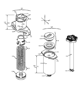
[0016] FIG. 1 is an exploded view of a removable syringe micro pump with wave
spring
in relation to a syringe and plunger in accordance with at least one
embodiment;
4
Date Recue/Date Received 2020-08-26
[0017] FIGs. 2A ¨ 2C are side and bottom views of the wave spring for the
removable
syringe micro pump with wave spring in accordance with at least one
embodiment;
[0018] FIGs. 3A - 3D are side, bottom and perspective views of the removable
syringe
micro pump with the wave spring enclosed therein in accordance with at least
one
embodiment;
[0019] FIGs. 4A and 4B are side and cut through views of the removable syringe
micro
pump with wave spring as attached to a syringe with the wave spring in it's
extended /
relaxed position within the barrel of the syringe and the plunger seal driven
towards the
nozzle in accordance with at least one embodiment;
[0020] FIGs. 5A and 5B are side and cut through views of the removable syringe
micro
pump with wave spring as attached to a syringe with the wave spring in it's
extended /
relaxed position within the barrel of the syringe and the plunger seal driven
towards the
nozzle and the plunger inserted to reset the removable syringe micro pump in
accordance
with at least one embodiment;
[0021] FIGs. 6A, 6B and 7A and 7B are side cut through views showing the
removable
syringe micro pump with wave spring in operation, driving the plunger seal
towards the
nozzle of the syringe in accordance with at least one embodiment of the
present invention;
and
[0022] FIG. 8 is a flow diagram presenting a high level review of at least one
method for
using a removable syringe micro pump with wave spring in accordance with at
least one
embodiment of the present invention.
DETAILED DESCRIPTION
[0023] Before proceeding with the detailed description, it is to be
appreciated that the
present teaching is by way of example only, not by limitation. The concepts
herein are not
limited to use or application with a specific system or method for a removable
syringe micro
pump with wave spring. Thus, although the instrumentalities described herein
are for the
convenience of explanation shown and described with respect to exemplary
embodiments, it
Date Recue/Date Received 2020-08-26
will be understood and appreciated that the principles herein may be applied
equally in other
types of systems and methods involving micro pumps and specifically syringe
micro pumps.
[0024] This invention is described with respect to preferred embodiments in
the following
description with reference to the Figures, in which like numbers represent the
same or
similar elements. Further, with the respect to the numbering of the same or
similar
elements, it will be appreciated that the leading values identify the Figure
in which the
element is first identified and described, e.g., element 100 first appears in
FIG. 1.
[0025] Turning now to FIG. 1 there is shown an exemplary embodiment of a
removable
syringe micro pump 100, hereinafter RSMP 100 in exploded form. As shown, RSMP
100 is
comprised principally of a pump housing 102 and a wave spring 104. As will be
more fully
appreciated by the description below, as RSMP 100 is removable, it may be
provided
separately to patients or parties desiring the use of a syringe micro pump,
and may be reused
by the same party or different parties and with the same syringe or different
syringes.
[0026] To facilitate the description of systems and methods for this RSMP 100,
the
orientation of RSMP 100 as presented in the figures are referenced to the
coordinate system
with three axes orthogonal to one another as shown in FIG. 1. The axes
intersect mutually at
the origin of the coordinate system, which is chosen to be the center of the
RSMP 100,
however the axes shown in all figures are offset from their actual locations
for clarity and
ease of illustration.
[0027] The pump housing 102 provides a first end 106, which may in part be
established
by reinforcing base 108. Opposite from the first end 106 is an attaching end
110, and at
least one sidewall 112 there between. For at least one embodiment, the
attaching end 110
has a set of flanges 114. As is shown more completely in FIGs 3A, 3B and 3C,
for at least
one embodiment the attaching end 110 further includes a seating collar which
is seated in
the open end of the syringe to assist with alignment when the RSMP 100 is
attached to a
syringe.
[0028] As shown, for at least one embodiment the pump housing 102 is
cylindrical. Of
course, for other embodiments, it may be desired to provide a pump housing 102
in a
configuration having a square, hexagon, or geometric cross section other than
a circle.
6
Date Recue/Date Received 2020-08-26
[0029] Within the pump housing 102 and proximate to the first end 106 is a
spring mount
base 116 structured and arranged to receive and anchor the wave spring 104 to
the pump
housing 102. For at least one embodiment, the spring mount base 116 has at
least one
mounting tab 118, structured and arranged to receive the wave spring 104.
[0030] As shown in FIG. 1 the wave spring 104 is in its extended / relaxed
position. A
wave spring is typically made from coiled flat wire with waves added to
provide the spring
effect. Wave springs can in general reduce spring height by 50% when compared
to coil
springs. As such they offer unique advantages of space savings. Moreover, the
height of the
compressed wave spring 104 when under tension is substantially less than the
height of the
wave spring 104 when extended.
[0031] Wave springs also produce a more consistent force across a range of
deflections
then traditional coil springs, which permit the RSMP 100 to be advantageously
precise in
terms of operation. In addition, unlike a traditional coil spring, a wave
spring 104 does not
develop torsional loads when compressed. As such wave spring 104 does not
impart a
rotation force during release of compression. Although typically used in
applications
requiring relatively short travel distances, wave spring 104 may be
manufactured offering 50
mm of travel or more. And, for at least one embodiment, multiple wave springs
may be
employed in series.
[0032] Wave spring stiffness is determined by thickness and type of spring
material as
well as the number of waves per turn of the spring. As such, embodiments of
RSMP 100
may be designed with different spring force characteristics so as to
accommodate different
liquids to be dispensed from the syringe
[0033] For at least one embodiment, the first end 120, or proximal end, of the
wave spring
104 is disposed about at least a portion of the spring mount base 116 such
that mounting tabs
118 engage the wave spring 104. As such, the distal end 122 of the wave spring
104 moves
away from the spring mount base 116 (and more specifically the reinforcing
base 108) and
the pump housing 102 as a whole, as tension in the wave spring 104 is released
as the wave
spring 104 transitions from a compressed first position to a relaxed/extended
second
6a
Date Recue/Date Received 2020-08-26
position. For at least one embodiment, RSMP 100 includes an end driver 124,
which
receives at least a portion of the distal end 122 of the wave spring 104.
[0034] Adjacent to the RSMP 100 in FIG. 1 is a syringe 126, having a barrel
128 defining
a chamber 130 between a nozzle 132 and a set of finger grips 134 adjacent to
the open end
136 of the syringe 126. A plunger seal 138 is understood and appreciated to be
the
moveable element within the barrel 128, that may slide along the inside of the
barrel 128
while maintaining a seal.
[0035] In some configurations, such as that shown, the plunger seal 138 may be
comprised
of a piston element 140 that is coupled to a seal element 142, generally
comprised of a
rubber, silicone, or other semi elastic material that may be used to provide
the movable seal.
For purposes of this discussion, the plunger seal 138 is understood to be this
element,
whether formed of one component or multiple components.
6b
Date Recue/Date Received 2020-08-26
CA 03039462 2019-04-03
WO 2018/071561 PCT/US2017/056170
[0036] Also shown in FIG. 1 is the plunger 144 removed from the syringe 126
and
disconnected from the plunger seal 138. When attached, the plunger 144 may be
used by an
operator engaging his or her fingers about the finger grips 134 to depress the
plunger seal
138 from the location within the chamber 130 above the nozzle 132 towards the
nozzle 132.
The reverse is also true.
100371 As may be appreciated in FIG. 1, the plunger 144 has an alignment
specific
attaching element 152, such as a rectangular flange. Likewise the plunger seal
138 has a
corresponding mating attaching clement 154, such as a rectangular receiver. As
such, for at
least one embodiment, the plunger 144 is engaged and disengaged from the
plunger seal 138
by twisting when the plunger attaching element 152 is disposed within the
plunger seal
mating attaching element 154. For yet another embodiment, not shown, the
plunger 144 has
a push or pull mechanism that releases an attaching element coupling to the
plunger seal
138.
[0038] When the plunger 144 is attached to the plunger seal 138, the operator
may draw
the plunger seal 138 away from the nozzle 132 towards the finger grips 134 by
way of the
plunger 144. This action creates a vacuum within the barrel 128 and permits
the syringe
126 to draw up a fluid solution or gas through the nozzle 132 and thus
substantially fill the
barrel 128 between the nozzle 132 and the plunger seal 138.
[0039] With respect to FIG. 1, it is to be appreciated that as shown, the
length of the
plunger 144 is actually longer than the barrel 128 of the syringe 126.
However, as the
plunger 144 is removable, when the plunger seal 138 has been disposed adjacent
to the
finger grips 134, or at whatever other desired location within the barrel 128
is deemed
appropriate, and the plunger 144 removed, the effective length of the syringe
126 is about
that of the barrel 128 and nozzle 132.
[0040] Returning to the RSMP 100 and more specifically the attaching end 110
of the
pump housing 102, it will be appreciated that the flanges 114 are structured
and arranged to
engage the finger grips 134 of the syringe 126. Moreover, when the pump
housing 102 is
disposed over the open end 136 of the syringe 126 adjacent to the finger grips
134, the
operator rotates the components relative to one another, such that the finger
grips 134 are
engaged by the flanges 114. In much the same way the finger grips 134 provide
a point of
leverage for the fingers of a human operator; the finger grips 134 provide a
point of leverage
for the RSMP 100.
[0041] For at least one embodiment, the flanges 114 may be provided with an
inset
depression of substantially the size and shape of the finger grips 134, so
that when rotated
into place, the finger grips 134 are received by the depressions, and thereby
locks the RSMP
7
CA 03039462 2019-04-03
WO 2018/071561 PCT/US2017/056170
100 in place. One or more additional springs, not shown, may provide a
separation force as
between the pump housing 102 and the syringe 126 to further engage the finger
grips 134
with the flange recesses and ward against unintended separation of the RSMP
100 from the
syringe 126.
[0042] It is also to be appreciated that the end driver 124 of the wave
spring 104 is
structured and arranged to engage the plunger seal 138 of the engaged syringe
126. In
optional embodiments, the distal end 122 of the wave spring 104 may directly
engage the
plunger seal 138.
[0043] When the compressed wave spring 104 is released, the release of tension
expands
the wave spring 104 outward from the pump housing 102 and against the end
driver 124
which in turn drives the plunger seal 138. As the pump housing 102 is locked
in place
against the finger grips 134 by the flanges 114, the expansion of the wave
spring 104 from
its compressed first position to the relaxed/extended second position drives
the distal end
122 against the end driver 124 which correspondingly drives the and the
plunger seal 138
towards the nozzle 132.
[0044] Moreover, it is to be understood and appreciated that the wave
spring 104 is
advantageously operating in place of the traditional plunger 144.
[0045] As is further shown in FIG. 1, the pump housing 102 has a dimension HD
146
along the sidewall 112. For at least one embodiment, this dimension HD 146 is
less than
the length of the syringe SL 148. For at least one embodiment, this dimension
HD 146 may
be about half the length SL 148. For at least one specific embodiment, this
dimension HD
146 is less than half the length SL 148. Moreover, it is understood and
appreciated that
RSMP 100 is compact and does not substantially add to the overall length of
the syringe
126 when attached.
[0046] More specifically, it should be understood and appreciated that the
dimension of
the sidewall 112 is less than the length of the syringe 126. For at least one
embodiment, the
dimension of the sidewall 112 of the pump housing 102 is less than half the
length of the
syringe 126. For at least one embodiment the dimension of the sidewall 112 of
the pump
housing 102 is less than one third of the length of the syringe 126. For at
least one
embodiment the dimension of the sidewall 112 of the pump housing 102 is less
than one
quarter of the length of the syringe 126. Moreover, it is understood and
appreciated that
RSMP 100 is compact and does not substantially add to the overall length of
the syringe
126 when attached.
8
CA 03039462 2019-04-03
WO 2018/071561 PCT/US2017/056170
[0047] Further still, as the plunger 144 is removed, RSMP 100 coupled to
syringe 126
may be disposed in a persons pocket, purse, pack or other space, and in
generally any
orientation during an infusion therapy session. As the motion of the wave
spring 104 is
entirely within the pump housing 102 and the barrel 128 of the syringe 126, it
will not catch
on, or be caught by, external items.
100481 Although RSMP 100 is advantageously operational without the use of
plunger
144, for at least one embodiment, RSMP 100, and more specifically the pump
housing 102,
provides a central aperture 150 such that the plunger 144 may pass directly
through the
RSMP 100 and engage the plunger seal 138. As such, plunger 144 may be used to
reset
RSMP 100 by using the plunger seal 138 to draw back the wave spring 104 to its
compressed first position, ready for use to once again drive forward the
plunger seal 138.
[0049] For at least one embodiment, RSMP 100 may further include a wave spring
104
restrainer 156 structured and arranged to restrain the wave spring 104 when it
has been
returned to the first position. For the exemplary embodiment shown in FIG. 1.
an
exemplary restrainer 156 is shown as a push button operating an internal lever
coupling to a
sliding pin engaging the edge of the wave spring 104 proximate to the distal
end 122. The
sliding pin may optionally engage a groove or slot in the side of the wave
spring 104.
Alternatively, a restrainer 156 may be an adjustable friction ring tightening
about the wave
spring 104. Of course it is understood and appreciated that a variety of
mechanical elements
may be employed as a restrainer 156 for the wave spring 104 within the
teaching of this
disclosure.
[0050] FIGs. 2A, 2B and 2C provide further illustrations to assist in
understanding and
appreciating the advantageous nature of the wave spring 104 as used in RSMP
100. More
specifically, in FIG. 2A the wave spring 104 is shown in its relaxed/extended
second
position 200. In this second position 200 the wave spring has a relaxed length
dimension
RL 202.
[0051] By applying compressive force 204, the wave spring 104 is
compressed such that
the coils 206 stack vertically upon one another as the wave elements in each
coil are
compressed down, shown in FIG. 2B. This is the compressed first position 208
of the wave
spring 104. In this state, the wave spring 104 is under tension as indicated
by arrows 210.
More specifically, the established tension force is an expansion force 210
which will drive
the wave spring 104 back to it's relaxed/extended second position 200 once
released from
the compressed first position 208.
[0052] As may also be appreciated in FIG. 2B, in this first position 208
the wave spring
has a compressed length dimension CL 212. As shown, the compressed length CL
212 is a
9
CA 03039462 2019-04-03
WO 2018/071561 PCT/US2017/056170
fraction of the relaxed length dimension RL 202. It is also to be appreciated
that the
compressed length dimension CL 212 is less than the pump housing 102 dimension
HD 146
(see FIG. 1), such that when wave spring 104 is in the first position 208 it
may be disposed
substantially within the pump housing 102.
[0053] As shown in FIG. 2C the nature of the coils 206 of the wave spring 104
is such
that the wave spring has an open center 214. As such, this open center 214
permits the
wave spring 104 to permit the plunger 144 to pass through the wave spring 104
and engage
the plunger seal 138 when the plunger is disposed through the aperture 150 of
the pump
housing 102.
[0054] Further, for at least one embodiment the wave spring 104 is
selected to have a
tension correlated to dispense the solution from the syringe 126 over a pre-
determined
period of time. In other words, a first wave spring 104 with a first tension
may be used to
dispense a solution at a first rate while a second wave spring 104 with a
second tension less
than the first tension may be used to dispense the same solution at a second
rate that is
slower than the first rate.
[0055] For at least one embodiment, the wave spring 104 is selected to
have a
relaxed/extended second position 200 that is equal to or slightly in excess of
the length of
the barrel 128 so as to ensure that all of the solution within the barrel 128
of the syringe 126
is dispensed. It is also understood and appreciated that the wave spring 104
need not be
compressed all the way back to first position 208 as shown.
[0056] Indeed, the wave spring 104 may be compressed so as to
substantially return the
majority of the wave spring 104 back to the pump housing 102 with the distal
end 122
extending from the pump housing 102. Moreover the compressed first position
208 is
understood and appreciated to be the initial position of wave spring 104 with
respect to the
pump housing 102 of RSMP 100 before the RSMP 100 is activated to drive the
plunger seal
138 towards the nozzle 132.
[0057] Moreover, the wave spring 104 restrainer 156 permits the RSMP 100 to be
attached to a syringe 126, but activation of the wave spring 104 is delayed
until such time as
infusion of the solution within the barrel 128 of the syringe 126 is desired.
[0058] FIGs. 3A, 3B, 3C and 3D provide respectively front, side, bottom
and perspective
views of the RSMP 100. For each illustration as shown, the wave spring 104 has
been
shown in a compressed first position 208 within the pump housing 102. In FIG.
3A the
compressed length dimension CL 212 of the wave spring 104 in relation to the
height HD
146 of the pump housing 102 may also be more fully appreciated. Indeed, with
respect to
FIGs. 3A, 3B, 3C and 3D, the removable nature of RSMP 100 may be further
appreciated,
for the elements of RSMP 100 may be appreciated as comprising the distinct
RSMP 100
without the presence of a syringe. As noted above, in FIGs. 3A-3D it may also
be
appreciated that for at least one embodiment, the attaching end 110 of RSMP
100 includes a
seating base 300 that is structured and arranged to fit within the open end
136 of the barrel
128 of syringe 126 as is shown in FIGs. 4B, 5B, 6A and 6B.
[0059] To summarize, for at least one embodiment provided is an RSMP 100,
including: a
pump housing 102 having a first 106 end and opposite thereto an attaching end
110, and at
least one sidewall 112 there between, the housing having a base 116 proximate
to the first
end 106 and, the attaching end 110 having an attacher 114 structured and
arranged to
temporarily engage a syringe 126; at least one wave spring 104 nested within
the housing
and attached proximate to the base 116, the wave spring 104 having a first
position 208
wherein the wave spring 104 is compressed under tension such that the initial
height of the
wave spring 104 is disposed within the pump housing 102, the wave spring 104
having a
second extended position 200 wherein, the release of tension extends the wave
spring 104
normally away from the pump housing 102, the wave spring 104 having a diameter
pre-
selected to pass within a barrel 128 of the engaged syringe 126, the wave
spring 104 further
having a distal end 122 structured and arranged to engage a plunger seal 138
of the engaged
syringe 126, wherein the release of tension between the first position 208 and
the second
position 200 permits the distal end 122 of the wave spring 104 to move the
plunger seal 138
towards a nozzle 132 of the syringe 126.
[0060] Moreover, another embodiment may be summarized as an RSMP 100,
including: a
cylindrical pump housing 102 haying a first end 106 with a base 116 and
opposite thereto an
attaching end 110 providing at least one flange 114 structured and arranged to
temporarily
bind with a set of finger grips 134 provided by a syringe 126 to which the
cylindrical pump
housing 102 may be temporarily attached, the cylindrical pump 100 having a
central
longitudinal axis; at least one wave spring 104 disposed within the pump
housing 102
proximate to the base 108 and about the longitudinal axis, the wave spring 104
being axially
compressible to fit within the cylindrical pump 102 when a distal end 122 of
the wave spring
104 is compressed to provide a first tensioned position 208, a height 212 of
the wave spring
11
Date Recue/Date Received 2020-08-26
104 when compressed to the first tensioned position 208 being about the same
as a length of
the cylindrical pump housing 102, the wave spring 104 further selected to have
a diameter
sufficient to slide within a barrel 128 of a syringe 126, the distal end 122
of the wave spring
104 structured and arranged to engage a plunger seal 138 of the engaged
syringe 126.
[0061] FIGs. 4A and 4B provide an assembled perspective view and corresponding
cut
through view of RSMP 100 engaged to syringe 126 in accordance with at least
one
embodiment. Moreover, in FIG. 4A the RSMP 100 has been disposed upon the
syringe 126
such that the flanges 114 of the pump housing 102 have engaged the finger
grips 134 of the
syringe 126. With respect to FIG. 4A it is also to be appreciated that the
overall length of
the syringe 126 with RSMP 100 attached is only slightly longer then the length
of the
syringe 126 by itself.
[0062] Also, with respect to FIG. 4A being an external view, it is to be
appreciated that
the state of the wave spring 104 within the assembly of the RSMP 100 and
syringe 126 need
not be overtly apparent ¨ especially if the barrel 128 of the syringe 126 is
opaque.
[0063] In FIG. 4B, presenting the cut through view along longitudinal axis 400
and
reference line arrows 4B in FIG. 4A, it can be seen that the wave spring 104
has expanded
from it's first compressed position within the pump housing 102 to a second
relaxed
position, and the exertion of force released during this change in positions
has driven the
plunger seal 138 down the length of the barrel 128 such that the plunger seal
138 is now
proximate to the nozzle 132. The nature of the coupling of RSMP 100 to the
barrel 128 of
syringe 126 may also be more fully appreciated. As shown, the engaging end 110
of RSMP
100 abuts the open end 136 of the barrel 128 of syringe 126. For at least one
embodiment,
the seating collar 300 is disposed within the open end 136, and facilitates
proper alignment
during attachment of RSMP 100 to the syringe 126. Moreover, it is to be
understood and
appreciated that the syringe remains external to the sidewall 112 of the pump
housing 102.
[0064] FIGs. 5A and 5B provide similar assembled perspective view (FIG. 5A)
and
corresponding cut through views view (FIG. 5B along reference line arrows 5B
in FIG. 5A)
of RSMP 100 engaged to syringe 126, and this time further showing the plunger
144 as
disposed through the aperture 150 of the pump housing 102 in accordance with
at least one
12
Date Recue/Date Received 2020-08-26
embodiment. As noted above, it is understood and appreciated that during
typical use of the
RSMP 100 the plunger will be removed so as to minimize the overall space
required for
operation, as well as to eliminate the opportunity for the plunger to become
bound or
otherwise restrained by some foreign object, which would in turn frustrate the
operation of
RSMP 100.
[0065] As shown in FIGs. 5A and 5B, the plunger 144 may be disposed through
RSMP
100 so as to engage the plunger seal 138 and draw it back from the nozzle 132
towards the
finger grips 134. As such, the plunger 144 may be used to reset RSMP 100 by
returning the
wave spring to it's compressed first position 208. In addition, as with a
traditional syringe,
drawing the plunger 144 back creates a vacuum within the chamber of the
syringe 126 such
that a fluid may be drawn into the syringe 126 from a source reservoir.
Moreover, the
plunger 144 may be employed to both prime the syringe 126 as well as reset the
RSMP 100.
[0066] FIGs. 6A and 6B, and 7A and 7B provide side cut through views
illustrating the
RSMP 100 in use. More specifically, FIG. 6A corresponds to the initial state
of RSMP 100
when attached to syringe 126 with plunger seal 138 disposed adjacent to the
finger grips
134. In actual use a fluid or medication, represented by dots 600, such as for
an infusion
therapy, would be present within the chamber 130 between the plunger seal 138
and the
nozzle 132.
12a
Date Recue/Date Received 2020-08-26
CA 03039462 2019-04-03
WO 2018/071561 PCT/US2017/056170
[0067] In FIG. 6B the RSMP 100 has been activated such that wave spring 104
has been
released from it's compressed/tensioned first position 208 and has engaged the
plunger seal
138 by way of the end driver 124 to move it approximately one-third of the way
along the
barrel 128 towards the nozzle 132, thus dispensing the fluid 600. In actual
use, the syringe
126, and more specifically the nozzle 132 would be coupled to tubing or other
delivery
conduit, which has not been shown so as to simplify the illustration.
[0068] In FIG. 7A the RSMP 100 has continued in operation such that the wave
spring
104 has now driven the plunger seal 138 approximately two-thirds of the way
along the
barrel 128 towards the nozzle 132, thus further dispensing the fluid 600.
[0069] And in FIG. 7B the RSMP 100 has ceased operation as the wave spring 104
has
now driven the plunger seal 138 substantially to the end of the barrel 128
such that
substantially all of the fluid has now been dispensed from the syringe 126.
[0070] Moreover, with respect to FIGs. 6A, 6B, 7A, 7B the expansion of the
wave spring
104 and thus the progression of the plunger seal 138, will continue until the
either the wave
spring 104 has reached its extended/relaxed second position, the plunger seal
138 has
encountered the end of the barrel 128, or a restraining mechanism (not shown)
is engaged to
prevent further expansion of the wave spring 104. For at least one embodiment,
the wave
spring 104 is selected to have a fully extended state that is equal to or
slightly in excess of
the length of the barrel 128 so as to ensure that all of the solution within
the barrel 128 of
the syringe 126 is dispensed.
[0071] Further, as evidenced especially in FIGs. 6A, 6B, 7A, 7B, the
motion of the wave
spring 104 occurs entirely within the RSMP 100 and the barrel 128 of the
syringe 126.
Moreover, there is no external change in the dimension of the coupled RSMP 100
and
syringe 126 during operation, e.g., no plunger 144 to be caught or interfered
with. It should
also be noted that although exemplary FIGs. 6A, 6B, 7A, 7B have demonstrated
the use of
RSMP 100 to drive the plunger seal 138 from a starting point proximate to the
finger grips
134 to the end of the barrel 128 proximate to the nozzle 132, e.g., a full
syringe, it is to be
understood and appreciated that RSMP 100 is equally applicable and appropriate
for use
with a syringe having an initial starting volume that is less than an
otherwise full syringe.
[0072] This small compact nature of the RSMP 100 and syringe 126 may
facilitate
infusion while the combined structure is disposed within a pocket. Further, as
the operation
of the wave spring 104 is a mechanical release of tension, it will be
understood and
appreciated that operation of the RSMP 100 is independent of orientation.
13
CA 03039462 2019-04-03
WO 2018/071561 PCT/US2017/056170
[0073] For shipping and transport, the RSMP 100 may be attached to the syringe
126
barrel 128 and the plunger 144 inserted through the aperture 150 of the pump
housing 102
and seated with plunger seal 138, which in turn is disposed against the bottom
of the syringe
126 adjacent to the nozzle 132. The syringe 126 and RSMP 100 are therefore a
compact
system. When use of the RSMP 100 is desired, the plunger 144 may be withdrawn
so as to
pull back the plunger seal 138, and in the process fill the barrel 128 with a
desired solution
for subsequent infusion.
[0074] With the plunger seal 138 properly disposed at a point, sufficient
to provide a
desired amount of solution, the plunger 144 may be disengaged from the plunger
seal 138
and discarded. With the plunger 144 now removed, the RSMP 100 and syringe 126
are
once again an advantageously compact system. As before, operation of the wave
spring 104
is entirely internal, such that there is no external change in size.
[0075] With respect to the above description of RSMP 100, the removable nature
of
RSMP 100 noted above may now be more fully appreciated. Indeed, the RSMP 100
is not
just removable, but also reusable. Thus RSMP 100 may be reset and attached to
new
syringes, which have been primed and delivered without a syringe pump thus
permitting a
savings across a spectrum of categories including but not limited to shipping,
storage,
materials and education of use. Once a patient or party is finished with RSMP
100, the
RSMP 100 may also be recycled back to a new party. Further still, an RSMP 100
may be
shared by multiple parties, obviously using RSMP 100 at different times.
[0076] Having described embodiments for the RSMP 100, other embodiments
relating to
at least one method 800 of using the RSMP 100 will now be discussed with
respect to the
above illustration and specifically FIG. 8. It will be appreciated that the
described method
700 need not be performed in the order in which it is herein described, but
that this is
merely exemplary of one method for using RSMP 100.
[0077] In general, the method 800 of use commences with providing a syringe
126
having a barrel 128 extending between a nozzle 132 and a set of finger grips
134, block 802.
For simplicity, it will be assumed that a plunger seal 138 is disposed within
the barrel 128
and proximate to the finger grips 134 with a solution disposed between the
plunger seal 138
and the nozzle 132. Moreover, this is a syringe 126 in a ready state for use
to provide a
solution for infusion to a patient.
[0078] The RSMP 100 having a set of flanges 114 structured and arranged to
engage the
finger grips 134 is then provided, block 804. Moreover, the RSMP 100 provided
is as
described above, comprised principally of a pump housing 102 and a wave spring
104.
14
Method 800 continues with the coupling of RSMP 100 to the syringe 126 by
disposing the
flanges 114 about the finger grips 134, block 806.
[0079] The wave spring 104 is then released to engage the plunger seal 138 of
the syringe
126 and drive the plunger seal 138 towards the nozzle 132, thus dispensing the
solution from
the syringe 126, block 808.
[0080] With respect to the above description regarding RSMP 100 and the
associated
method 700 of use, for at least one embodiment the wave spring 104 may be
sheathed by at
least one volute spring, not shown. More specifically, one or more volute
springs may be
used, at least in part, to protect the wave spring and help ensure that it
does not buckle
during compression or expansion. For yet another embodiment, the wave spring
104 may be
combined with a volute spring in an ordered alignment to cooperatively
interact and drive
the plunger seal 138 of the syringe 126 towards the nozzle 132. Moreover,
whether acting
at least in part as a sheath about the wave spring 104 or as additional spring
elements in
alignment with the wave spring 104, the one or more volute springs may be as
the volute
spring used in the removable micro pump set for and described in US Patent
Application
15/291,758 filed October 12, 2016 and entitled System and Method for a
Removable
Syringe Micro Pump With Volute Spring.
[0081] Changes may be made in the above methods, systems and structures
without
departing from the scope hereof. It should thus be noted, that the matter
contained in the
above description and/or shown in the accompanying drawings should be
interpreted as
illustrative and not in a limiting sense. Indeed, many other embodiments are
feasible and
possible, as will be evident to one of ordinary skill in the art. The claims
that follow are not
limited by or to the embodiments discussed herein, but are limited solely by
their terms and
the Doctrine of Equivalents.
Date Recue/Date Received 2020-08-26