Note: Descriptions are shown in the official language in which they were submitted.
CA 03039746 2019-04-08
WO 2018/108430
PCT/EP2017/079408
-1 -
AEROSOL-GENERATING SYSTEM WITH FLUID SENSOR
The present invention relates to an aerosol-generating system with a pump
having an
inlet and an outlet, the inlet being connectable to a liquid storage portion
and a fluid channel.
The present invention also relates to a method for generating an aerosol.
One type of aerosol-generating system comprises a liquid storage portion, a
pump
and a vaporiser. During a puff of the user a stream of liquid aerosol-
generating substrate
such as e-liquid is actively pumped from the liquid storage portion to the
vaporiser by means
of the pump. In such a system ¨ when the liquid in the liquid storage portion
is used up ¨ the
vaporiser may be heated, while no liquid aerosol-generating substrate is
provided to the
vaporiser. As a result, the user will inhale heated air, which does not
contain a generated
aerosol. Inhaling heated air only may be unpleasant for the user and is thus
unwanted. Also,
heating of the vaporiser or a wicking material when there is no liquid present
may result in
the release of undesirable products.
It would therefore be desirable to provide an improved aerosol-generating
system
which prevents activation of the system once the liquid aerosol-generating
substrate in the
liquid storage portion is used up.
According to a first aspect of the invention there is provided an aerosol-
generating
system, comprising a pump having an inlet and an outlet, the inlet being
connectable to a
liquid storage portion. The system also comprises a fluid channel fluidly
connected to the
pump and a fluid sensor. The fluid sensor is configured to determine a
presence of liquid
aerosol-forming substrate in the fluid channel preferably by measuring an
electrical property
of the fluid comprised in the fluid channel.
The aerosol-generating system of the present invention allows detection of the
presence of liquid aerosol-forming substrate in the fluid channel.
Beneficially, a vaporiser can
be deactivated when the sensor detects that no fluid is present in the fluid
channel. The
inhalation of only hot air is thus prevented, thereby prohibiting an
unpleasant experience for
the user and the generation of undesirable products. The detection of the
sensor that no
more liquid aerosol-forming substrate is present in the fluid channel may be
utilized to
indicate that a fresh liquid storage portion must be supplied.
The aerosol-generating system may further comprise a dispensing device for
dispensing the liquid aerosol-forming substrate, wherein the dispensing device
is in fluid
communication with the outlet of the pump. The fluid channel and the fluid
sensor may be
provided between the pump and the dispensing device. The fluid sensor may be
provided
adjacent to the dispensing device, wherein the dispensing device may be
provided adjacent
CA 03039746 2019-04-08
WO 2018/108430
PCT/EP2017/079408
-2-
to the vaporiser. However, the fluid sensor may be provided anywhere in the
system
between the liquid storage portion and the dispensing device.
If the fluid sensor is provided downstream of the pump between the pump and
the
dispensing device, the liquid aerosol-forming substrate can be optimally used,
since all of the
liquid aerosol-forming substrate is consumed before the sensor detects that no
more liquid is
present in the fluid channel. In more detail, even if the liquid in the liquid
storage portion is
used up, liquid may still be present in the fluid channel. In this case, the
system will still
operate, until the fluid in the fluid channel downstream of the pump is used
up. Thus, the
liquid storage portion may be completely depleted of liquid aerosol-forming
substrate before
the fluid sensor detects that no more substrate is present.
The fluid sensor may be configured to measure an electrical property of the
fluid
comprised in the fluid channel. The electric property measured by the fluid
sensor may be
the electrical resistance of the fluid comprised in the fluid channel.
Typical fluids in the fluid channel are ambient air or liquid aerosol-forming
substrate.
When the liquid storage portion still comprises liquid aerosol-forming
substrate and the
substrate is pumped towards the dispensing device by the pump, the substrate
will be
present in the fluid channel. If, however, the liquid storage portion is
emptied of substrate, no
more substrate will subsequently be pumped through the fluid channel. Thus,
ambient air will
be present in the fluid channel. The electrical resistance of ambient air is
different from the
electrical resistance of liquid aerosol-forming substrate. Typically, the
electrical resistance of
ambient air is higher than the electrical resistance of liquid aerosol-forming
substrate. Thus,
by measuring the electrical resistance of the fluid comprised in the fluid
channel, the sensor
may determine whether air or substrate is present in the fluid channel.
For measuring the electrical resistance of the fluid comprised in the fluid
channel, the
fluid sensor may comprise a first electrode and a second electrode.
The resistance between the first electrode and the second electrode may depend
on
the amount of liquid aerosol-forming substrate held in the liquid channel. For
example, the
electrical resistance may increase as the amount of liquid aerosol-forming
substrate held in
the fluid channel decreases.
The electrodes are preferably arranged at walls of the fluid channel. For
example, the
first electrode is provided at a first channel wall of the fluid channel and
the second electrode
is provided at a second channel wall of the fluid channel. The electrodes may
preferably be
in direct contact with the fluid comprised in the fluid channel. The first
electrode may be
disposed opposite to the second electrode. The electrodes may alternatively be
arranged in
the liquid channel. The first electrode and the second electrode may be
arranged at opposite
ends of the liquid channel. At least one of the first and second electrodes
may be arranged at
CA 03039746 2019-04-08
WO 2018/108430
PCT/EP2017/079408
-3-
or in contact with the wall of the liquid channel. The first and second
electrodes may be
arranged to each partially surround the liquid channel. The first and second
electrodes may
be arranged concentrically about a common axis of the liquid channel.
The second electrode may substantially follow the path of the first electrode.
This
may enable the spacing between the first and second electrodes to remain
consistent along
the length of the first and second electrodes. The second electrode may be
arranged
substantially parallel to the first electrode.
The electrodes may be any suitable type of electrode. For example, suitable
types of
electrodes include point electrodes, ring electrodes, plate electrodes or
track electrodes. The
first electrode and the second electrode may be the same type of electrode.
The first
electrode and the second electrode may be different types of electrodes.
The electrodes may by any suitable shape. For example, the electrodes may be:
square, rectangular, curved, arcuate, annular, spiral or helical. The
electrodes may be
substantially cylindrical. The electrodes may comprise one or more sections
that are
substantially linear, non-linear, planar or non-planar. The electrodes may be
rigid. This may
enable the electrodes to maintain their shape. The electrodes may be flexible.
This may
enable the electrodes to conform to the shape of the fluid channel.
The electrodes may have a length, a width and a thickness. The length of the
electrodes may be substantially greater than the width of the electrodes. In
other words, the
electrodes may be elongate. The thickness of the electrodes may be
substantially less than
the length and the width of the electrodes. In other words, the electrodes may
be thin. Thin
electrodes and elongate electrodes may have a larger surface area to volume
ratio. This may
improve the sensitivity of measurements.
The electrodes may comprise any suitable material. The electrodes may comprise
any suitable electrically conductive material. Suitable electrically
conductive materials include
metals, alloys, electrically conductive ceramics and electrically conductive
polymers. The
materials may include gold and platinum. The electrodes may be coated with a
passivation
layer. The electrodes may comprise or be coated in material that is
sufficiently non-reactive
so as not to react with or contaminate the liquid aerosol-forming substrate.
The electrodes
may comprise transparent or translucent material.
For measuring the electrical resistance, the fluid sensor may comprise a
voltage
divider circuit. A voltage divider circuit enables the measurement of the
electric resistance
between the first and second electrode of the fluid sensor. However, any known
method of
measuring the resistance of the fluid between the two electrodes may be
employed.
The measured electrical property of the fluid may also be the dielectric
constant of the
fluid. In this regard, the electrodes may constitute a capacitor. The fluid
between the
CA 03039746 2019-04-08
WO 2018/108430
PCT/EP2017/079408
-4-
electrodes serves ¨ in this case ¨ as a dielectric medium, wherein the
dielectric constant of
this fluid may be measured by measuring the capacitance of the capacitor or
any known
method. The dielectric constant of air is different from the dielectric
constant of liquid aerosol-
forming substrate and can be used to distinguish these fluids.
The electric property, preferably the electric resistance or dielectric
constant of the
fluid in the fluid channel may be indicative of the specific fluid. By
determining the electrical
resistance of the fluid in the fluid channel, it may be possible to identify
the chemistry of the
liquid. In this regard, the electrical resistance of the fluid in the fluid
channel may depend
upon the chemistry of the liquid. Thus, it may be identified whether or not
the correct type of
liquid is used. For example, different liquid aerosol-forming substrates may
be used in the
system by subsequently providing liquid storage portions with different
substrates. These
different substrates may have different electric properties, which may be
detectable by the
fluid sensor. The fluid sensor may not only detect whether or not substrate is
present in the
fluid channel, but additionally detect what kind of substrate is present in
the fluid channel.
Beneficially, the system may be operated on basis of the detection of the
specific substrate
by the fluid sensor. For example, the temperature of a vaporiser may be
controlled
depending on the used substrate. Also, the heating time may be controlled
depending on the
used substrate.
The dispensing devise may be a nozzle or a tubing segment, also referred to as
tube.
The dispensing devise may comprise a tube and a nozzle at the distal end of
the tube. The
tube may comprise any appropriate material, for example glass, metal, for
example stainless
steel, or plastics material, for example PEEK. The size of the tube may match
that of the
pump outlet. For example, the tube may have a diameter of about 1 to 2
millimetres but other
sizes are possible. The tube may be connected to the pump outlet via silicon
tubing. The
tube may be directly connected to the pump outlet.
The dispensing devise may be provided to deliver the liquid aerosol-forming
substrate
to a vaporiser. The vaporiser may comprise a heater for heating the supplied
amount of liquid
aerosol-forming substrate. The heater may be any device suitable for heating
the liquid
aerosol-forming substrate and volatilizing at least a part of the liquid
aerosol-forming
substrate in order to form an aerosol. The heater may exemplarily be a heated
coil, a heated
capillary, a heated mesh or a heated metal plate. Preferably, the vaporiser is
provided as a
heating coil extending ¨ with respect to the dispensing device ¨ in a
longitudinal direction of
the dispensing device. The diameter of the heating coil may be chosen such
that the heating
coil can be mounted around the dispensing device. The heating coil may be
mounted
transverse to the dispensing device. The heating coil may overlap with the
nozzle of the
dispensing device. In some examples, there may be a distance between the
nozzle of the
CA 03039746 2019-04-08
WO 2018/108430
PCT/EP2017/079408
-5-
dispensing device and the heating coil. The length of the heating coil may be
2 millimetres to
9 millimetres, preferably 3 millimetres to 6 millimetres. The diameter of the
heating coil may
be 1 millimetre to 5 millimetres, preferably 2 millimetres to 4 millimetres.
The heater may comprise only a single heating element or a plurality of
heating
elements. The temperature of the heating element or elements is preferably
controlled by
electric circuitry.
The electric circuitry may comprise a microprocessor, which may be a
programmable
microprocessor. The microprocessor may be part of a controller. The electric
circuitry may
comprise further electronic components. The controller may be configured to
regulate a
supply of power to the vaporiser. Power may be supplied to the vaporiser
continuously
following activation of the system or may be supplied intermittently, such as
on a puff-by-puff
basis. The power may be supplied to the vaporiser in the form of pulses of
electrical current.
Preferably, the supply of power to the vaporiser is controlled depending upon
the
measurement of the fluid sensor. When the fluid sensor detects that no more
liquid is present
in the fluid channel, power supply to the vaporiser may be prohibited.
Additionally or
alternatively, the power supply to the vaporiser may be controlled on basis of
the type of
liquid aerosol-forming substrate in the fluid channel. For example, the
specific heating regime
may be executed on basis of the type of substrate.
For supplying power to the vaporiser, the system may comprise a power supply,
.. typically a battery. As an alternative, the power supply may be another
form of charge
storage device such as a capacitor. The power supply may require recharging
and may have
a capacity that allows for the storage of enough energy for one or more
smoking
experiences; for example, the power supply may have sufficient capacity to
allow for the
continuous generation of aerosol for a period of several minutes. In another
example, the
power supply may have sufficient capacity to allow for a predetermined number
of puffs or
discrete activations of the vaporiser. The controller may be connected to the
power supply to
control the supply of power from the power supply to the vaporiser.
The vaporiser may also be provided as a piezoelectric transducer or vibrating
membrane.
The pump may be a micro pump. The pump may also be provided as a micro stepper
motor pump or a piezoelectric pump.
The pump may be controlled by the controller. The controller may stop the
operation
of the pump when the fluid sensor detects that no more liquid aerosol-forming
substrate is
present in the fluid channel. Power may be supplied to the pump by means of
the power
supply.
CA 03039746 2019-04-08
WO 2018/108430
PCT/EP2017/079408
-6-
The pump and preferably the vaporiser may be triggered by a puff detection
system.
Alternatively, the pump and preferably the vaporiser may be triggered by
pressing an on-off
button, held for the duration of the user's puff.
The puff detection system may be provided as a sensor, which may be configured
as
an airflow sensor and may measure the airflow rate. The airflow rate is a
parameter
characterizing the amount of air that is drawn through the airflow path of the
system per time
by the user. The initiation of the puff may be detected by the airflow sensor
when the airflow
exceeds a predetermined threshold.
The liquid storage portion may be adapted for storing the liquid aerosol-
forming
substrate to be supplied to the dispensing device. The liquid storage portion
may be
configured as a container or a reservoir for storing the liquid aerosol-
forming substrate.
Preferably, the liquid storage portion is capable of being coupled to the pump
inlet by
a respective coupling hermetically sealed against surrounding atmosphere.
Preferably, the
couplings are configured as self-healing pierceable membranes. The membranes
avoid
undesired leaking of the liquid aerosol-forming substrate stored in the liquid
storage portion.
For coupling the replaceable liquid storage portion to the pump a respective
needle-like
hollow tube may be pierced through a respective membrane. When the pump is
coupled to
the liquid storage portion, the membranes avoid undesired leaking of the
liquid aerosol-
forming substrate and leaking of air from and into the liquid storage portion.
The liquid storage portion may be any suitable shape and size. For example,
the
liquid storage portion may be substantially cylindrical. The cross-section of
the liquid storage
portion may, for example, be substantially circular, elliptical, square or
rectangular.
The liquid storage portion may be a disposable article replaced once the
liquid
storage portion is empty or below a minimum volume threshold. The system may
output a
signal such as an optical or acoustical signal when the fluid sensor detects
that the fluid
channel is empty of liquid aerosol-forming substrate. The signal may indicate
that a new
liquid storage portion must be provided to replace the old empty liquid
storage portion or that
the liquid storage portion needs to be refilled.
The aerosol-forming substrate is a substrate capable of releasing volatile
compounds
that can form an aerosol. The volatile compounds may be released by heating
the aerosol-
forming substrate. The aerosol-forming substrate may comprise plant-based
material. The
aerosol- forming substrate may comprise tobacco. The aerosol-forming substrate
may
comprise a tobacco-containing material containing volatile tobacco flavour
compounds,
which are released from the aerosol-forming substrate upon heating. The
aerosol-forming
substrate may alternatively comprise a non-tobacco-containing material. The
aerosol-forming
CA 03039746 2019-04-08
WO 2018/108430
PCT/EP2017/079408
-7-
substrate may comprise homogenised plant-based material. The aerosol-forming
substrate
may comprise homogenised tobacco material.
The aerosol-generating system may be an electrically operated system.
Preferably,
the aerosol-generating system is portable. The aerosol-generating system may
have a size
comparable to a conventional cigar or cigarette. The smoking system may have a
total length
between approximately 30 millimetres and approximately 150 millimetres. The
smoking
system may have an external diameter between approximately 5 millimetres and
approximately 30 millimetres.
According to a second aspect of the invention, there is provided a method for
generating an aerosol. The method comprises the step of providing a pump for
pumping
liquid aerosol-forming substrate, the pump having an inlet and an outlet, the
inlet being
connectable to a liquid storage portion. A fluid channel is provided fluidly
connected to the
pump. Furthermore, a fluid sensor is provided, wherein the fluid sensor
determines a
presence of liquid aerosol-forming substrate in the fluid channel.
Features described in relation to one aspect may equally be applied to other
aspects
of the invention.
The invention will be further described, by way of example only, with
reference to the
accompanying drawings in which:
Fig. 1 shows an
illustrative cross section of the inventive aerosol-generating
system;
Fig. 2 shows an illustrative cross section of the inventive sensor and
the fluid
channel;
Fig. 3
shows an illustrative wiring diagram of a voltage divider circuit which
may be employed in the inventive sensor;
Fig. 4 shows an exemplary measurement diagram of the inventive sensor;
and
Fig. 5 shows an further exemplary measurement diagram of the inventive
sensor.
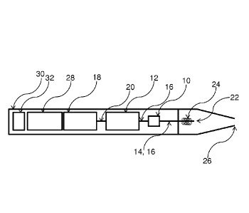
The aerosol-generating system shown in Fig. 1 comprises a fluid sensor 10. The
fluid
sensor 10 is arranged between a pump 12 and a dispensing device 14. The fluid
sensor 10 is
arranged at a fluid channel 16. The fluid sensor 10 measures the electrical
resistance of the
fluid in the fluid channel 16. Thereby, the fluid sensor 10 determines whether
liquid aerosol-
forming substrate is present in the fluid channel 16.
CA 03039746 2019-04-08
WO 2018/108430
PCT/EP2017/079408
-8-
The pump 12 is configured to pump liquid aerosol-forming substrate from a
liquid
storage portion 18 towards the fluid channel 16 and the fluid sensor 10. The
pump 12 is
fluidly connected with the liquid storage portion 18 by means of an additional
fluid channel
20.
After the liquid aerosol-forming substrate passes the fluid channel 16 and the
fluid
sensor 10, the liquid aerosol-forming substrate is delivered towards the
dispensing device
14. The dispensing device 14 is configured as a tubing segment ending in a
nozzle 22.
Around the dispensing device 14, a heater 24 is arranged. The heater 24 is
configured as a
heating coil.
The heater 24 heats the liquid aerosol-forming substrate in the dispensing
device 14
such that an aerosol is delivered from the nozzle 22 towards a mouth end 26 of
the aerosol-
generating system. The aerosol is subsequently inhaled by a user. The heater
24 is powered
by a battery 28.
The fluid sensor 10, pump 12, dispensing device 14, fluid channel 16, nozzle
22,
heater 24, mouth end 26 and battery 28 are arranged in a housing 30. The
housing 30
confines a main body of the system. The housing 30 also comprises a controller
32. The
controller 32 controls the activation of the heater 24. When the fluid sensor
10 detects that no
liquid aerosol-forming substrate is present in the fluid channel 16, the
controller 32 will
deactivate the heater 24. The controller 32 also controls the pumping action
of the pump 12.
The controller 32 is part of electric circuity which may also determine the
type of fluid in the
fluid channel 16 on basis of the electric resistance of the fluid. The
controller 32 may
deactivate the heater 24, if an undesired fluid is present in the fluid
channel 16.
In Fig. 1, the liquid storage portion 18 is also arranged in the housing 30.
However,
the liquid storage portion 18 may be configured as a separate replaceable
cartridge which
may be attachable to an inlet of the pump 12.
Fig. 2 depicts the fluid sensor 10 in more detail. In this regard, Fig. 2
shows the fluid
channel 16, wherein a first electrode 34 and a second electrode 36 of the
fluid sensor 10 are
arranged at the wall of the fluid channel 16.
The first electrode 34 is arranged at the wall of the fluid channel 16 such
that the tip
of the first electrode 34 is in direct contact with the fluid in the fluid
channel 16. The second
electrode 36 is arranged on the opposite site of the wall of the fluid channel
16 also in direct
contact with the fluid in the fluid channel 16. The first and second
electrodes 34, 36 are
arranged to measure the electrical resistance of the fluid between the
electrodes 34, 36 and
thus of the fluid in the fluid channel 16. The electrodes 34, 36 are supported
in a carrier 38
for dimensional stability. The fluid sensor 10 has a length and width of 1
millimetre to 1
centimetre and preferably around 3 millimetre. The thickness of the fluid
sensor 10 is 0,5
CA 03039746 2019-04-08
WO 2018/108430
PCT/EP2017/079408
-9-
millimetre to 3 millimetre and preferably around 1,5 millimetre. The
electrodes have a
diameter of 0,9 millimetre. The electrodes have a length of 1 to 5 millimetre
and preferably
around 3 millimetre. The distance between the electrodes should be as small as
possible
without impeding the flow of liquid, ideally 1 millimetre or the internal
diameter of the tube.
Fig. 3 shows a voltage divider circuit which is used to determine the
electrical
resistance of the fluid in the fluid channel 16.
In Fig. 3, a conventional voltage divider circuit is modified in that a
conventional first
resistor is replaced by the first and second electrode 34, 36 and the fluid in
the fluid channel
16 between the electrodes 34, 36. Apart thereof, the voltage divider circuit
consists of the
known elements of a voltage divider circuit. In more detail, a second resistor
40 is provided.
The electrical resistance of the second resistor 40 is known. The electrical
resistance of the
second resistor can be chosen as required and is chosen suitable with respect
to the
electrical resistance of the liquid aerosol-forming substrate. The electrical
resistance of the
second resistor is chosen in the range of 5 to 20 Megaohm and preferably
around 12
Megaohm or approximately equal to the resistance between the two electrodes
when liquid is
present. Different aerosol forming substrates will present different
resistances therefore this
may need to be specified during the design process. However most resistor
values in this
range will provide a significant voltage difference when liquid is present vs
when it is not. The
electrical resistance of the liquid aerosol-forming substrate is comparable
within different
liquid aerosol-forming substrates such as e-liquids. A known voltage is
applied to the circuit.
An analog-to-digital converter 42 is connected to the center tap of the
voltage divider circuit.
By using the measured voltage, the known electrical resistance of the second
resistor 40 and
the known applied voltage, the controller, which is connected with the analog-
to-digital
converter 42, computes the electrical resistance of the first resistor. Since
the electrical
resistance of the electrodes 34, 36 is also known, the controller 32 thus
computes the
electrical resistance of the fluid in the fluid channel. At the analog-to-
digital converter 42, the
measured voltage decreases if the electrical resistance of the fluid between
the electrodes
increases and vice versa.
Fig. 4 shows an exemplary measurement of the fluid sensor 10. Fig. 4 depicts
the
voltage which is measured at the analog-to-digital converter 42. The diagram
shows the
voltage over time. The electrical resistance of the second resistor 40 was set
to 12
Megaohm. At first, no liquid aerosol-forming substrate is present in the fluid
channel 16. Only
air is present in the fluid channel 16. Thus, the measured voltage is low,
corresponding to a
high electric resistance of the fluid in the fluid channel 16. The electric
resistance was
determined to be 18 Megaohm when no substrate was present in the fluid channel
16. This
measurement is denoted by reference sign 44. Before the fluid channel 16 is
fully filled with
CA 03039746 2019-04-08
WO 2018/108430
PCT/EP2017/079408
-10-
liquid aerosol-forming substrate, bubbles emerge, i.e. a mixture of liquid
aerosol-forming
substrate and air. Thus, fluctuating electrical resistance values are
determined by the fluid
sensor 10. This measurement is denoted by reference sign 46. When the fluid
channel 16 is
fully filled with liquid aerosol-forming substrate, the measured voltage is
high, corresponding
to a comparatively low electric resistance of the liquid aerosol-forming
substrate in the fluid
channel 16 (reference sign 48). The electric resistance was determined to be
10 Megaohm
when the fluid channel 16 was fully charged with liquid aerosol-forming
substrate. The same
principle applies when ¨ at first ¨ liquid aerosol-forming substrate is
present in the fluid
channel and ¨ subsequently ¨ air is present in the fluid channel. In this
case, liquid aerosol-
forming substrate will be followed by bubbles and eventually by air.
Fig. 5 is another exemplary measurement of the fluid sensor 10 with other
parameters than the parameters used in Fig. 4. In the measurement as used in
Fig. 5, the
electrical resistance of the second resistor 40 was set to 5,6 Megaohm. The
measurement
was conducted with different fluids in the fluid channel 16. The fluids used
were water 50, a
.. fluid 52 with glycerol, denoted 80PG/20VG, and a further fluid 54 with
higher glycerol
content, denoted 20PG/80VG. Between measurements of the different fluids, the
fluid
channel 16 was cleaned using isopropanol and water to prevent contamination of
the fluid
channel 16. The measurements were delayed until the respective fluids 50, 52,
54 had filed
the fluid channel 16 and a stable measurement signal could be obtained. Fig. 5
shows the
measured resistance against the time.
The measurement depicted in Fig. 5 shows that the three fluids 50, 52, 54
could
clearly be distinguished from one another based upon the measured electrical
resistance. It
has been observed that the measured electrical resistance increased over time.
Without
being bound to any theory, it is believed that this increase was a result of
polarization of the
fluids 50, 52, 54. Particularly the fluid 54 with high glycerol content was
prone to polarization,
since glycerol does not dissociate in water and so the fluid 54 contained a
low initial ion
count resulting in faster and more pronounced polarization. To avoid an
increase of the
measured electrical resistance over time, alternating current could be used
for measuring the
electrical resistance.
The exemplary embodiments described above illustrate but are not limiting. In
view of
the above discussed exemplary embodiments, other embodiments consistent with
the above
exemplary embodiments will now be apparent to one of ordinary skill in the
art.