Note: Descriptions are shown in the official language in which they were submitted.
AIRCRAFT DOOR STRUCTURE
TECHNICAL FIELD
[0001] The application relates generally to doors and, more particularly, to
aircraft door
structures.
BACKGROUND
[0002] For some conventional doors for aircraft, a door latching system
consists of a
moveable latching mechanism and a fixed catch. The moveable latching mechanism
that is actuated by the user is mounted to the door itself, with the mechanism
being
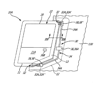
integrated inside the door structure. The area surrounding the door has the
fixed or
immoveable catch of the latching system.
[0003] This traditional design means that the structure of the door has to be
hollow to
allow cables or rods of the moveable latching mechanism to run from the door
handle to
the latching locations. These passageways need a certain depth/width to allow
proper
clearance, and may prevent the use of a more compact or weight-efficient
structure for
the door. Furthermore, the installation of the moveable latching mechanism is
complex
because it is typically inserted into the door after it has been constructed
through
multiple access cut-outs in the door that need to be covered over afterwards
to
eliminate the risk of foreign object damage (FOD) jamming the mechanism.
Furthermore, this conventional design may be more difficult to repair or
replace
because access to the moveable latching mechanism is restricted through a few
small
openings in the door.
SUMMARY
[0004] In one aspect, there is provided an aircraft, comprising: a fuselage
defining an
outer surface and an inner surface, the fuselage having a door frame
delimiting a door
opening extending through the fuselage and providing access to an interior
thereof, the
door frame having a latch housing portion defining a latch housing cavity
extending
along a length of the door frame; a door mounted to the door frame and
displaceable
1
CA 3040076 2019-04-11
between an open position and a closed position, the door having a peripheral
portion
with an outer wall and an inner wall extending from the outer wall inwardly
toward the
interior of the fuselage, the outer and inner walls delimiting a cavity of the
peripheral
portion; and a door latch assembly having a first latch member fixedly mounted
to the
door, and a door manipulator mounted to one of the door and the fuselage and
coupled
to a second latch member disposed within the latch housing cavity of the door
frame,
the door manipulator configured to be manipulated to displace the second latch
member to engage and disengage the first latch member.
[0005] There is provided a door structure, comprising: a door frame delimiting
a door
opening, the door frame having a latch housing portion defining a latch
housing cavity
extending along a length of the door frame; a door mounted to the door frame
and
displaceable between an open position and a closed position, the door having a
peripheral portion with an outer wall and an inner wall delimiting a cavity of
the
peripheral portion; and a door latch assembly having a first latch member
fixedly
mounted to the door, and a door manipulator mounted to one of the door and the
fuselage and coupled to a second latch member within the latch housing cavity
of the
door frame, the door manipulator configured to be manipulated to displace the
second
latch member to engage and disengage the first latch member.
[0006] There is provided a method of assembling a door structure, the method
comprising: providing a door frame delimiting a door opening and having a
latch
housing portion defining a latch housing cavity; mounting a door to the door
frame, the
door having a peripheral portion with an internal cavity; fixedly mounting a
first latch
member to the door; and displaceably mounting a second latch member within the
latch
housing cavity of the door frame, the second latch member being displaceable
to
engage and disengage the first latch member.
DESCRIPTION OF THE DRAWINGS
[0007] Reference is now made to the accompanying figures in which:
[0008] Fig. 1 is a schematic side view of a rotorcraft in accordance with an
embodiment
of the present disclosure;
2
CA 3040076 2019-04-11
[0009] Fig. 2A is a schematic side view of a door structure of the rotorcraft
shown in
Fig. 1; and
[0010] Fig. 2B is a cross-sectional view of part of the door structure of Fig.
2A, taken
along the line 11B-IIB in Fig. 2A.
DETAILED DESCRIPTION
[0011] Fig. 1 shows an aircraft. The aircraft shown in Fig. 1A is a rotorcraft
100,
according to one example embodiment of the aircraft disclosed herein. The
rotorcraft
100 features a rotor system 110, blades 120, a fuselage 130 defining a cabin
180, a
landing gear 140, and an empennage 150. The rotor system 110 rotates the
blades
120. The rotor system 110 includes a control system for selectively
controlling the pitch
of each blade 120 in order to selectively control direction, thrust, and lift
of the rotorcraft
100. The fuselage 130 represents the body of the rotorcraft 100 and is coupled
to rotor
system 110 such that the rotor system 110 and the blades 120 may move the
fuselage
130 through the air. The landing gear 140 supports the rotorcraft 100 when the
rotorcraft 100 is landing and/or when the rotorcraft 100 is at rest on the
ground. The
empennage 150 represents the tail section of the aircraft and features
components of a
rotor system 110' and blades 120'. The blades 120' may provide thrust in the
same
direction as the rotation of blades 120 so as to counter the torque effect
created by the
rotor system 110 and the blades 120. The fuselage 130 defines an outer surface
132
and an inner surface 134. The outer surface 132 is exposed and visible, and
forms the
outer surface of the body of the rotorcraft 100. The inner surface 134 faces
toward the
interior of the rotorcraft 100.
[0012] The fuselage 130 has multiple door structures 10 or door assemblies.
Each door
structure 10 includes a door frame 12 (see Fig. 2A) and a door 10A. The door
frame 12
forms the structure to which the door 10A is mounted or fitted. The door frame
12 is the
structure which surrounds some or all of the door 10A. In the depicted
embodiment, the
door frame 12 is a component of, or integral with, the fuselage 130. The door
frame 12
delimits a door opening 136 or doorway which extends through the fuselage 130
between the inner and outer surfaces 132,134. The door openings 136 provide
access
to the interior of the fuselage 130, to the interior of the cabin 180 for
example. Each
3
CA 3040076 2019-04-11
door opening 136 is covered by one of the doors 10A. It will be appreciated
that entry
into the fuselage 130, and exit from fuselage 130, is achieved through the
door
openings 136 by opening or closing the corresponding doors 10A.
[0013] In Fig. 1, each door 10A is a body which has a window or transparency
to admit
light. The door 10A is thus a windowed structure. The doors 10A shown in Fig.
1 are
passenger doors which open and close to allow passengers to enter and exit the
cabin
180 of the rotorcraft 100. Other doors 10A are within the scope of the present
disclosure. For example, in an alternate embodiment, the door 10A is a cargo
door that
admits no light therethrough. In another alternate embodiment, the door 10A is
a panel
that admits no light therethrough. Therefore, reference to doors 10A herein
does not
limit the door 10A to being only a light-admitting structure.
[0014] Referring to Figs. 2A and 2B, each door 10A is any suitable moveable
part or
barrier which is mounted to the door frame 12 about one of the door openings
136
using any suitable structure such as hinges. It will be appreciated that the
door 10A
may also slide with respect to the door frame 12, and thus may have suitable
mounting
structure to enable such functionality. Each door 10A is displaceable between
an open
position to provide access to the interior of the fuselage 130 via the door
opening 136,
and a closed position (shown in Fig. 2A) to block the door opening 136 and
prevent
access therethrough.
[0015] The rotorcraft 100 also has a door latch assembly 30. The door latch
assembly
30 is used to open and close the door 10A, and to latch and unlatch the door
10A to the
door frame 12. The door latch assembly 30 thus forms a latching mechanism for
the
door 10A. When the door 10A is latched, it is in a closed position and is
maintained in
that position by the door latch assembly 30. When the door 10A is unlatched,
it is in an
open position. Locks or a locking mechanism can be used with the door 10A
and/or the
door latch assembly 30 to lock and unlock the door 10A when it is latched. As
will be
described in greater detail below, some components of the door latch assembly
30 are
positioned on or within the door 10A, and other components of the door latch
assembly
30 are positioned on or within the door frame 12. The door 10A and door frame
12 have
4
CA 3040076 2019-04-11
structure, described in greater detail below, some of which may be used to
house or
position components of the door latch assembly 30.
[0016] With respect to the door 10A, and referring to Fig. 2A, the door 10A
has a door
body 11 with a peripheral portion 13. The peripheral portion 13 of the door
10A is a
structural segment of the door 10A that delimits the periphery of the door
10A. The
peripheral portion 13 gives structure to the door 10A along its periphery to
reinforce the
strength and stiffness of the door 10A along its periphery. The door body 11
also has an
interior portion 11A positioned inwardly of the peripheral portion 13 and
delimited
thereby. The peripheral portion 13 in the depicted embodiment extends along
all of the
periphery of the door body 11. In an alternate embodiment, the peripheral
portion 13
extends along less than all of the periphery of the door body 11. The door 10A
has a
window element 20 in the depicted embodiment which allows light to be admitted
through the door 10A. The window element 20 is any suitable transparency or
other
body to achieve this purpose. The window element 20 may have any suitable
shape or
size, and may be made from any suitable material such as a polymer and glass.
In the
depicted embodiment, the window element 20 is a single layer of glass. Other
configurations for the window element 20 are also possible. The window element
20
covers or occupies a window opening 22 which extends through the interior
portion 11A
of the door body 11. The window element 20 has an outer window surface 24A
which
forms the external surface of the window element 20, and an inner window
surface 24B
(see Fig. 2B). In the depicted embodiment, some of the peripheral portion 13
delimits
the window opening 22 and the window element 20. In an alternate embodiment,
the
door 10A is free of a transparency or window element.
[0017] Fig. 2B shows the peripheral portion 13 and window element 20 in cross-
section
and according to one embodiment of the present disclosure. The peripheral
portion 13
includes an outer wall 14. The outer wall 14 is the segment of the peripheral
portion 13
closest to the outer surface 132 of the fuselage 130. In the depicted
embodiment, the
outer wall 14 is an outermost wall of the peripheral portion 13. The outer
wall 14
extends between a first end 14A, sometimes referred to herein as the "window
end
14A", and a second end 14B, sometimes referred to herein as the "fuselage end
14B".
The second end 14A is the extremity of the outer wall 14 which is closest to a
center of
Date Regue/Date Received 2021-05-28
the window opening 22, and furthest from the fuselage 130. The fuselage end
14B is
the extremity of the outer wall 14 which is closest to the fuselage 130, and
furthest from
the center of the window opening 22. An inner wall 16 extends from the outer
wall 14
inwardly. When the door 10A in the depicted embodiment is in the closed
position, the
inner wall 16 extends from the outer wall 14 inwardly toward the interior of
the fuselage
130. The outer and inner walls 14,16 meet and are bonded or fastened together.
The
inner wall 16 has a V-shape in the illustrated cross-section. The inner wall
16 includes a
first segment 16A and a second segment 16B in the depicted embodiment. The
first
and second segments 16A,16B of the inner wall 16, and the outer wall 14, are
interconnected to form a triangular cross-sectional shape of the peripheral
portion 13.
The triangular cross-sectional shape of the peripheral portion 13 may or may
not be
present throughout the entire extent of the peripheral portion 13. The first
segment 16A
of the inner wall 16 extends inwardly from the outer wall 14 at the second end
14A. The
first segment 16A of the inner wall 16 extends inwardly in a direction toward
the
fuselage 130 from the outer wall 14 at the second end 14A. In other
embodiments, the
inner wall 16 might have a different shape than the triangular shape depicted
in Figure
2B.
[0018] In the embodiment shown in Fig. 2B, the inner wall 16 and the outer
wall 14
delimit a cavity 15 of the peripheral portion 13, such that the peripheral
portion 13 is
hollow along at least part of its length. Stated differently, the cavity 15
may or may not
be present throughout the entire extent of the peripheral portion 13. The
presence of
the cavity 15 results in the door 10A having some depth or thickness at least
along the
peripheral portion 13. The cavity 15 in Fig. 2B is an internal cavity of the
peripheral
portion 13 at the cross-section shown, and is closed on all sides by the outer
and inner
walls 14,16. In some embodiments, some of which are described below, the
cavity 15 of
the peripheral portion 13 is at least partially filled.
[0019] For example, and as shown in Fig. 2B, the cavity 15 is filled or bonded
with a
stiffener 15A. The stiffener 15A is any object or material which increases the
stiffness of
the peripheral portion 13, and thus its strength, to reinforce the peripheral
portion 13
against out of plane forces. The stiffener 15A may be made of any suitable
material,
and have any suitable shape or configuration to achieve such functionality.
For
6
CA 3040076 2019-04-11
example, in the depicted embodiment, the stiffener 15A has substantially the
same
cross-sectional shape as the cavity 15 (i.e. triangular). The stiffener 15A
fully occupies
the cavity 15, and abuts against the outer and inner walls 14,16 of the
peripheral portion
13. In an alternate embodiment, the stiffener 15A occupies less than the
entirety of the
cavity 15, and/or extends across the cavity 15 between the outer and inner
walls 14,16.
The stiffener 15A in the depicted embodiment is made from a composite
material. The
stiffener 15A in the depicted embodiment is a composite foam. The foam may
have a
relatively low density. Thus, in the depicted embodiment, the cavity 15 in the
door 10A
is filled with a foam stiffener 15A abutting against the inner and outer walls
16,14 along
at least some of the length of the cavity 15. In Fig. 2B, the stiffener 15A is
shown in the
cavity 15 of the peripheral portion 13 of the door 10A, and it may also be
present in
other parts of the door 10A.
[0020] The cavity 15 may have other shapes as well. In an alternate
embodiment, the
cavity 15 has a "C" shape in cross-section. In an alternate embodiment, the
cavity 15 is
partially open, and defined by the inner and outer walls 16,14 forming a "T"
shape in
cross-section.
[0021] As mentioned above, the door frame 12 may have structure used to house
or
position components of the door latch assembly 30. Referring to Fig. 2B, the
door frame
12 has a latch housing portion 17. The latch housing portion 17 is a portion
of the door
frame 12 which houses some or all of components of the door latch assembly 30.
The
latch housing portion 17 defines a latch housing cavity 17A which extends
along at least
some of the length of the door frame 12. The one or more components of the
door latch
assembly 30 are positioned in the latch housing cavity 17A, and are thus
protected by
the latch housing portion 17. The latch housing portion 17 may take any
suitable
configuration to achieve such functionality. For example, in the depicted
embodiment,
the latch housing portion 17 includes a cover 17B or trim panel. The cover 17B
is
removably mounted to one of the inner and outer surfaces 134,132 of the
fuselage 130.
As shown in Fig. 2B, the cover 17B is mounted to the inner surface 134 of the
fuselage
130, and projects inwardly from the inner surface 134 toward the cabin 180.
The cover
17B is a protector or housing that is bolted or attached to the fuselage 130,
and defines
the latch housing cavity 17A between itself and the inner surface 134. Thus,
in the
7
CA 3040076 2019-04-11
embodiment where the latch housing portion 17 includes the cover 17B, the
removability of the cover 17B makes the components of the door latch assembly
30
easy to access and install because the cover 17B is fitted onto aircraft
structure as a
"bolt-on" instead of a "build-in". In contrast to some conventional
structures, the latch or
latch components are not trapped within the structure of the aircraft, or
accessible only
thorough small cut-outs in the aircraft structure.
[0022] Other configurations for the latch housing portion 17 are possible. In
an
alternate embodiment, the latch housing portion 17 forms part of the fuselage
130 and
the latch housing cavity 17A is an internal cavity located within the fuselage
130. The
latch housing portion 17 and the latch housing cavity 17A have vertical
orientations in
the depicted embodiment, but may also have a different orientation (e.g.
horizontal or
inclined to both the horizontal and vertical).
[0023] Referring to Figs. 2A and 2B, the door latch assembly 30 is now
described in
greater detail. The door latch assembly 30 has a first latch member 32 and a
second
latch member 34. The first and second latch members 32,34 cooperate with one
another to latch the door 10A in the open or closed position, and to unlatch
the door
10A so that it is free to move relative to the door frame 12.
[0024] As shown in Fig. 2A, the first latch member 32 is fixedly mounted to
the door
10A. By "fixedly mounted", it is understood that the first latch member 32
does not
displace with respect to the door 10A. The first latch member 32 moves with
the door
10A between the open and closed positions. The first latch member 32 may be
mounted to the inner or outer surface of the door 10A, it may be positioned
within the
door 10A or exposed thereon, and may be positioned at any location on the door
10A
such as along an edge thereof. A particular configuration of the first latch
member 32 is
described below, and the present disclosure also includes other configurations
of the
first latch member 32.
[0025] The second latch member 34 is displaceable. The second latch member 34
is
displaceable with respect to the door frame 12 to engage with, and disengage
from, the
first latch member 32. The second latch member 34 is disposed in whole or in
part
8
CA 3040076 2019-04-11
within the latch housing cavity 17A of the door frame 12, and is thus shielded
by the
latch housing portion 17.
[0026] The second latch member 34 is displaced when a person manipulates a
door
manipulator 36. The door manipulator 36 is any object which is manipulated by
a user
to open and close the door 10A. The door manipulator 36 is mounted to one or
both of
the door 10A and the fuselage 130 (e.g. the door frame 12). In Fig. 2A, a
portion of the
door manipulator 36 is shown mounted to the door frame 12, and another portion
is
shown mounted to the door 10A, as described in greater detail below. The door
manipulator 36 is coupled or mechanically linked to the second latch member 34
such
that manipulation of the door manipulator 36 will cause displacement of the
second
latch member 34. The door manipulator 36, and its coupling to the second latch
member 34, may take any suitable form to achieve such functionality.
[0027] For example, in Fig. 2A, the door manipulator 36 includes, or is in the
form of, a
handle 36A mounted to the fuselage 130 in proximity to, on, or over the door
frame 12.
The handle 36A is installed on the fuselage 130 in an area easily accessible
by the
occupant. In Fig. 2A, the second latch member 34 includes a cable or rod 34A
extending along a height of the door frame 12. The handle 36A is mechanically
linked to
the rod 34A such that rotation of the handle 36A causes the rod 34A to
linearly displace
in a direction parallel to its upright or vertical orientation. The door
manipulator 36 also
includes a switch 36B positioned on the door 10A to be accessible by an
occupant. The
switch is operatively connected to the handle 36A in any suitable way, such
that the
switch 36B may be pushed or activated by the occupant to latch and unlatch,
and/or
lock and unlock, the handle 36A and prevent it from rotating. The switch 36B
in the
depicted embodiment is accessible only from outside of the fuselage 130, but
it may
also be positioned to be accessible from within the fuselage 130. In one
possible
embodiment, the switch 36B is an electro-mechanical component which is
electrically
coupled to the handle 36A.
[0028] Other configurations for the door manipulator 36 and its coupling to
the second
latch member 34 are possible. In an alternate embodiment, the door manipulator
36
includes, or is in the form of, a knob which is turned to displace a wire or
cable of the
9
CA 3040076 2019-04-11
second latch member 34. In another alternate embodiment, the door manipulator
36
includes, or is in the form of, a button which is pushed to displace the
second latch
member 34. It will therefore be appreciated that the door manipulator 36, the
manner by
which it is manipulated, and/or the manner by which it is coupled to the
second latch
member 34, may vary.
[0029] The manipulation of the door manipulator 36 displaces the second latch
member
34 within the latch housing portion 17. In Fig. 2A, the displacement of the
rod 34A is an
axial movement along the longitudinal axis of the rod 34A. At least parts of
the rod 34A
are displaceable in a direction along a height of the door 10A. Other types of
displacement of the second latch member 34 are possible. The second latch
member
34 displaces to engage and disengage the first latch member 32, so as to latch
and
unlatch the door 10A.
[0030] Therefore, in Figs. 2A and 28, the fixed first latch member 32 is
disposed on
the door 10A, and the displaceable second latch member 34 is disposed on the
structure of the fuselage 130 surrounding and supporting the door 10A, which
is the
door frame 12 in the depicted embodiment. No components of the door latch
assembly
30 are positioned within the cavity 15 of the door 10A. It will thus be
appreciated that
the moving parts of the door latch assembly 30 are not mounted to or in the
door 10A.
This configuration of the first and second latch members 32,34 allows for
positioning the
moveable second latch member 34 on the area surrounding the door 10A (e.g. the
door
frame 12), which is typically large enough to accommodate the moveable second
latch
member 34. This configuration of the first and second latch members 32,34
allows for
optimization of the stiffness of the door 10A, to minimize the depth or
thickness of the
door 10A thus providing weight savings and increased cabin space, and to
increase the
size of the window element 20 of the door 10A to provide improved visibility
because
the moveable portion of the door latch assembly 30 is not present in the door
10A.
[0031] One possible configuration of the first and second latch members 32,34
is now
described with reference to Figs. 2A and 2B. The first latch member 32
includes one or
more strikers 32A which are fixedly mounted to the door 10A. In Fig. 2A, the
first latch
member 32 includes two strikers 32A - an upper striker 32A' fixedly mounted to
an
CA 3040076 2019-04-11
upper end of the door 10A and a lower striker 32A" fixedly mounted to a lower
end of
the door 10A. Each striker 32A is any suitable object (e.g. catch, bolt,
plate, male
portion, etc.) which does not displace with respect to the door 10A, and which
is
engaged by the moveable second latch member 34. The strikers 32A in Fig. 2A
are
separate from one another, and free of any mechanical link to one another. In
an
alternate embodiment, the strikers 32A are horizontally spaced apart for a
door 10A that
opens vertically by pivoting about a horizontal axis.
[0032] Still referring to Fig. 2A, the rod 34A of the second latch member 34
is a rigid
elongated body extending between an upper end and a lower end. The rod 34A has
one or more latches 38. In Fig. 2A, the rod 34A has two latches 38 - a lower
latch 38' at
a lower end of the rod 34A and an upper latch 38" at an upper end of the rod
34A. The
latches 38 in the depicted embodiment are "female" components meant to receive
the
"male" strikers 32A. Other configurations for the latches 38 are possible and
within the
scope of the present disclosure. When the door manipulator 36 is manipulated
by the
operator, the rod 34A is displaced so that the lower latch 38' engages or
disengages
the lower striker 32A", and so that the upper latch 38" engages or disengages
the
upper striker 32A'. The latches 38 are displaceable between a first position
in which the
latches 38 are disengaged from the strikers 32A and the door 10A is unlatched,
and a
second position in which the latches 38 are engaged with the strikers 32A and
the door
10A is latched.
[0033] Reference is made to US patent application number 16/161,921 filed
October
16, 2018.
[0034] Referring to Figs. 2A and 2B, there is disclosed a method of assembling
the
door structure 10. The method includes providing the door frame 12, and
mounting the
door 10A to the door frame 12. The method also includes fixedly mounting the
first latch
member 32 to the door 10A, and displaceably mounting the second latch member
34
within the latch housing cavity 17A of the door frame 12 so that the second
latch
member 34 is displaceable to engage and disengage the first latch member 32.
[0035] In an embodiment, mounting the door 10A includes forming the door 10A
prior
to mounting it. Forming the door 10A includes forming the peripheral portion
13 of the
11
Date Regue/Date Received 2021-05-28
door 10A from a single composite laminate delimiting the internal cavity 15.
The
composite laminate is a product made by bonding together two or more layers of
composite material. It is therefore possible to make the peripheral portion 13
of the door
10A, as well as other parts of the door 10A, from a single composite laminate
or part,
thereby reducing the number of cures required to form the door 10A to a single
cure.
[0036] Forming the peripheral portion 13 may also include filling the cavity
15 at least
partially with the stiffener 15A. The composite foam of the stiffener 15A may
be
positioned between the layers of the single composite laminate or wrapped by
said
layers, so that the layers are cured and bonded together around the stiffener
15A in a
single, one-step cure. This contrasts with some conventional techniques for
making a
door which has the moveable components of the latching system. These
techniques
may involve assembling separate inner and outer composite skins to form the
cavity,
and fishing the moveable components of the latching mechanism inside the door
after
the assembly. Such a technique involves two steps, and also requires that
multiple cut-
out panels be machined in the door to access the moveable components of the
latching
mechanism inside the door. By helping to eliminate these steps, the forming
steps
described above help to make the door 10A lighter and more cost-effective to
manufacture.
[0037] The above description is meant to be exemplary only, and one skilled in
the art
will recognize that changes may be made to the embodiments described without
departing from the scope of the invention disclosed. For example, although
described
herein as an installed feature of an aircraft, the door structure 10 may be
provided as an
assembly or grouping of its constituent parts. Still other modifications which
fall within
the scope of the present invention will be apparent to those skilled in the
art, in light of a
review of this disclosure, and such modifications are intended to fall within
the
appended claims.
12
CA 3040076 2019-04-11