Note: Descriptions are shown in the official language in which they were submitted.
CA 03040976 2019-04-17
1 -
Interactively Controlling a Machine with Feedback of a
Regulating Parameter
Description
Cross reference to related applications
The present application refers to and claims the priority of the German patent
application
2016 119 853.6, which was filed on 18 October 2016, the disclosure of which is
hereby
expressly incorporated by reference into the subject matter of the present
application in
its entirety.
Field of the invention
10 The invention relates to a human-machine interface as well as to a
method of interactively
controlling a regulating function of a machine by a manual regulating input.
Prior art
Human-machine interfaces for the interactive control of machines are known for
example
for training and/or setting up an injection moulding machine wherein a series
of manual
regulating processes are necessary. To this end, the corresponding machines
can be
connected to and/or incorporate a human-machine interface. For such tasks, it
is known
to use hard-wired logic elements and/or key fields, keyboards, manipulators
and/or touch-
sensitive screens. The human-machine interface can be connected to the machine
by an
appropriate data processing unit or a machine control system and thereby
enable
complex regulating processes to be effected via this connection.
A control device for a plastics-processing machine having multi-touch
functionality in the
form of a human-machine interface is known from DE 10 2010 051 639 Al which
forms
the preamble of the independent claims. Machine operations and production
parameters
can be input by an operator and are displayable and changeable on this control
unit.
CA 03040976 2019-04-17
- 2 -
A method and a device are known from EP 1 656 245 B1 for interactively
controlling a
synthetic material injection moulding machine working, in particular,
cyclically. The
interactive controlling process is effected by means of an input unit which is
connected to
the injection moulding machine by a data processing unit. Input fields can be
assigned
virtually.
DE 10 2005 052 725 B3 depicts an operating element for an injection moulding
machine
with a screen for the representation of program data which is configured
partially as a
touch screen. Virtual function keys can be provided outside of the screen as
well as on
the screen. For this purpose, the screen protrudes the touch screen.
DE 601 13 685 T2 discloses an interface for controlling a machine having
configurable
keys, i.e. soft keys, in regions parallel to the screen.
US 2004/0021698A1 proposes a graphic interface for a multi-function device
having a
touch-sensitive display on which a hierarchy of graphical objects for the
multi-function
operation process is displayable to a user.
Object of the invention
Proceeding from this prior art, the object of the present invention is to
improve the
process of interactively controlling a complex machine in regard to the
ergonomics,
security and intuitive operability thereof.
This object is achieved by a human-machine interface incorporating the
features of
claim 1 as well as by a method incorporating the features of claim 10 and an
injection
moulding machine incorporating the features of claim 16. Advantageous further
developments form the subject matter of the dependent claims. The individual
features
specified in the claims are combinable with one another in a technologically
meaningful
way and can be supplemented by explanatory matter from the description and by
details
from the Figures wherein further variants of embodiments of the invention are
presented.
The human-machine interface comprises a regulating input unit and a parameter
input
unit that is operable independently thereof. A regulating function of a
machine can be
controlled manually by means of the regulating input unit in dependence on a
regulating
input. A regulating function can be understood, in particular, as meaning the
adjustment
of a parameter or preferably of a movement of a moveable component of the
machine
CA 03040976 2019-04-17
- 3 -
that is actually taking place. The regulating function can be controlled
manually,
simultaneously and interactively by an appropriate manual regulating input on
the
regulating input unit. This can be effected, in particular, bidirectionally,
what for example
can correspond to a forward and backward movement of the moveable component.
In
principle, such a movement can be effected at different speeds, whereby in
this case, the
speed serving as a parameter is influenceable by means of the parameter input
unit.
Thereby, comparatively high regulating speeds can be desirable in order to
enable the
corresponding regulating function to be concluded and/or achieved as fast as
possible. In
contrast thereto, however, lower regulating speeds can also be desirable
particularly in
the region of the end position in the event of an occurrence of high pressures
and/or high
forces during the regulating function process.
Insofar as parameters are mentioned in the context of this application, then
this refers not
only to the speed of a movement but also to the parameters which are entered
for
operating an injection moulding machine. These are pressure, temperature, time
points
such as, for instance, switchover times between the injecting and dwell
pressure phase,
time points for operating the ejector, partial cycle times, e.g. in the case
of multi-
component injection processes, path information for the mould closing unit,
mould height,
dosage and amount to be injected, flow rate, the quantity of addable
components and
much more besides such as are commonly within the competence of a specialist
in
injection moulding machines. The preferred field of employment of the
invention then lies
in the field in which mutually dependent parameters are to be entered.
For the purposes of controlling the regulating function, an operator of the
machine can
simultaneously manually control the regulating parameter thereof by means of
the
parameter input unit. Consequently, two functionally mutually dependent
parameters can
thereby be controlled independently. Conceivable here for example are
processes of
controlling/entering the pressure and temperature, a pressure and flowrate as
well as
preferred variables such as the path of a mould together with the path of an
ejector or
else too, the acceleration and/or speed of one or more elements of the
injection moulding
machine.
There is thus a best possible compromise especially during the process of
training the
machine for a new process, from comparatively rapid execution of the
regulating function
and avoidance of possibly arising unwanted effects in the event of regulating
speeds that
are too high or movements giving rise to collisions if, for instance, an
ejector is driven into
CA 03040976 2019-04-17
- 4 -
a self-opening mould. Due to the parameter display unit which is arranged
together with
the parameter input unit on the human-machine interface, it is possible for
the operator of
the machine to always be fully conscious of the regulating parameters. In
addition, the
manually controlled regulating parameter is capable of being fed back as a
nominal value
or as a currently occurring value actually arising in the machine by means of
the
parameter display unit. The regulating parameter is functionally dependent on
the
regulating function. In the example of the input of a speed in connection with
a correcting
variable, this means that the speed will be indicated by the parameter display
unit which
is arranged together with the parameter input unit for the input of the speed
on the
human-machine interface so that the operator will always be aware of these
parameters.
Thus, the security, ergonomics and intuitive operability of the machine can be
improved
since the operator of the machine receives a direct feedback, in particular,
precisely there
where the regulating speed can also be manually controlled, i.e. on the speed
input unit,
in order to remain with the example of speed.
Arranged together can be understood as meaning a neighbouring, one-above-the-
other,
next-to-each-other and/or superimposed arrangement and/or a spatial
association. The
feedback of the regulating parameter such as a speed can be effected in
different ways,
in particular, by highlighting a nominal value i.e. the manually entered
parameter or a
current value of the parameter actually occurring in the machine, in
particular, in the form
of a regulating parameter magnitude that is dependent thereon. The direct
feedback of
the regulating parameter such as a regulating speed can be effected optically,
in haptic
and/or tactile manner, in particular, in the form of a scale indication.
In a preferred exemplary embodiment of the human-machine interface, provision
is made
for the parameter display unit to comprise a bar graph indicator that is
aligned along a
longitudinal touch-sensitive surface of the parameter input unit. A bar graph
indicator can
be understood in the broadest sense as a laminar dial readout, in particular,
a pictorial
depiction of a bar or a bar chart. It is, however, also conceivable for the
bar graph
indicator to be variably curved and, in particular, have a rounded shape.
The bar graph indicator can be realised passively or actively with illuminated
segments
particularly in the form of pixels, as a ribbon-type indicator with a
multiplicity of illuminated
segments and/or in some other way.
Preferably, the bar graph indicator comprises a plurality of separately
controllable
illuminated segments such as light emitting diodes which are disposed linearly
one behind
CA 03040976 2019-04-17
- 5 -
the other. The touch-sensitive longitudinal surface is arranged along the bar
graph
indicator. During a setting process on the touch-sensitive surface, it is
thereby possible for
the bar graph indicator to follow an operating input that is required
therefor. In particular, a
process of stroking the touch-sensitive surface by means of a part of the body
can be
followed directly by a corresponding lengthening or shortening of a bar of the
bar graph
indicator and thus the entered or selected regulating speed can be
simultaneously fed
back visually.
In a further preferred exemplary embodiment, provision is made for a
modulatable
illuminated readout by means of which a state of the machine is displayable to
be
arranged at least laterally of or on each side of the bar graph indicator.
Modulatable can
be understood as meaning that the indicator is changeable regarding its
colour, flashing
pattern, flashing frequency, brightness and/or any other arbitrary property
for indicating
the state of the machine. Preferably, at least the colours green for in order
and red for
critical can be used and, if so required, an arbitrary number of intermediate
tones for the
purposes of symbolizing a state between in order and critical. It is
particularly preferred
that not only the illuminated readout be modulated but also additionally the
parameter
display unit, whereby, if necessary, the majority of the illuminated segments
of the bar
graph indicator can be modulated in exactly the same way as the illuminated
readout.
This results in the advantage that even in the case of a parameter value of
zero in the
event of which for example none of the illuminated segments of the bar graph
indicator is
illuminated, the state of the machine can still be indicated. Because the
illuminated
readout is arranged laterally of or on each side of the bar graph indicator,
feedback is
likewise provided at the point where the parameter such as the regulating
speed is
arranged to be input. Consequently, intuitive readout of the state and
improvement in
operational security are possible.
In a further exemplary embodiment, the bar graph indicator and/or the
illuminated readout
are conical, whereby the illuminated readout preferably extends in the shape
of a Y over
the human-machine interface. Extension of the illuminated readout in the shape
of a Y
can be understood as meaning that, commencing from a corner of the human-
machine
interface, it extends on each side of the bar graph indicator and then runs
off at an angle
parallel to two of the sides of the human-machine interface commencing from
said corner.
Consequently, the illuminated readout is always visible from any viewpoint of
a display
area of the human-machine interface. Moreover, the illuminated readout cannot
therefore
be completely covered by any possible activities of parts of the body of an
operator such
CA 03040976 2019-04-17
- 6 -
as a hand or an arm for example, i.e. even then it is always visible.
Detection of the state
can thus be improved, and security of operation can be increased.
A further alternative of the human-machine interface envisages that it
comprises an
independently operable selection input unit. The regulating function can be
selected by a
manual control action by means of the selection input unit. Due to the
independent
operability of the selection input unit, the operator of the machine is always
aware of
which regulating functions he has selected from a plurality of regulating
functions. It is
particularly preferred and conceivable that the selection of the regulating
function be
likewise fed back. In particular, directly at the selection input unit and/or
additionally as
well as at the regulating input unit.
Preferably, the parameter display unit and/or the parameter input unit are
arranged
between an input unit especially for permanently assigned keys and the
regulating input
unit. The regulating parameter can be entered in a particularly simple manner
and its
feedback be observed due to this central arrangement.
In a further exemplary embodiment of the human-machine interface, the input
unit and/or
the parameter input unit can comprise glass cylinders in the form of
haptically perceptible
operating elements which are let into and are flush with the surface. Glass
can be
understood as meaning any kind of transparent material, i.e. acrylic glass as
well. Due to
the surface-flush arrangement, a surface of the human-machine interface can
easily be
cleaned whereby tactile feedback is nevertheless still possible due, in
particular, to the
palpability of the glass cylinders. In particular, the operating elements may
exhibit a
customary or conventional force-path characteristic that is typical of a key
or push-button.
Preferably, the let-in glass cylinders can be part of a multi-touch type of
input equipment
similar to a protective glass on a touch-sensitive screen, i.e. be in the form
of sensor keys
which nevertheless enable the desirable haptic or tactile feedback process to
occur.
Moreover, it is conceivable for the physically present operating elements to
be optically
assigned, in particular, by static and especially imprinted symbols so that
they are
identifiable with a static function. This likewise enables a secure operation
of the human-
machine interface since system-critical operations and, in particular,
selection processes
at the input unit are always to be found again in the same place. In
consequence,
inadvertent faulty operations i.e. inadvertent placement of a component part
of the
machine can be avoided.
CA 03040976 2019-04-17
- 7 -
Furthermore, however, operating elements of the regulating input unit can be
assigned
dynamically, in particular in dependence on the need, characterised according
to a
particular selection at the selection input unit or else, if necessary, the
input unit as well.
For example, they can be illustrated in the form of an appropriate symbol on
an additional
display. An optimum compromise between a static and dynamic use of the
operating
elements can thereby be found. An operation is effected consciously and by
means of
statically located and statically assigned operating elements. The actual
process of
controlling the regulating function taking place thereafter can in fact be
effected by
means, in particular, of likewise statically arranged operating elements,
although they
could be assigned dynamically to the respective regulating function.
Furthermore, it is
additionally possible for the parameter setting unit to also be arranged
statically on the
human-machine interface i.e. to always be associated with the same location.
Thus, the
further critical magnitude too, namely the regulating parameter such as a
regulating
speed can always be manually controlled in a secure and consciously aware
manner.
In accordance with a further alternative, the human-machine interface can be
equipped
with a touch-sensitive screen which is operable independently of the input
units described
hereinabove. Preferably, the previously described input units are arranged at
the edge of
the screen. It is particularly preferred that a touch-sensitive surface of the
screen should
not only cover its display unit but also the rest of the input units. In one
design of the
touch-sensitive screen in the form of a so-called multi-touch display, it is
possible to
simultaneously process a plurality of inputs in the form of contacts at
different points of
the screen. Further functions of the human-machine interface can be realised
by means
of the touch-sensitive screen, in particular, a graphical representation of a
process, such
as e.g. a training process by the manual control system, the display of a
keyboard for the
input of data and/or the like. Due to the independently operable input units
in combination
with the touch-sensitive screen, a secure intuitive operation can be effected
without
having to thereby forego the flexibility offered by the touch-sensitive
screen.
Furthermore, the regulating input unit, the parameter input unit and/or the
input unit can
be directly connected to a machine control system of the machine by means of a
serial
real-time interface, in particular. Manual control of the machine can thereby
be carried out
without time delay or at least without any time delay worth mentioning.
Possible
programming processes and/or computer-intensive training processes can be
carried out,
if necessary, by means of the touch-sensitive screen and/or by means of a
suitable
computer unit such as in the machine control system and/or at the human-
machine
CA 03040976 2019-04-17
- 8 -
interface. Independently thereof, manual control can be effected directly and
without time
delay by means of the real-time interface. This makes it possible for a
parameterisation
process in real time.
The method of interactively controlling a regulating parameter of a machine is
carried out
.. in particular by means of a human-machine interface that is described
above. To that
extent, the advantages described hereinabove then result. Firstly, the
regulating input unit
is provided. This comprises, in particular, the haptically perceptible
operating elements, in
particular, with permanently associated pictograms and/or symbols, for
example, in the
form of arrows and/or plus, minus signs. In the case of a bidirectional
control system, the
.. operating elements can be provided in pairs. Detection of a manual entry
for manually
controlling the regulating function of the machine is effected by means of the
regulating
input unit. Also provided, moreover, is the parameter input unit by means of
which
simultaneous detection of a further manual parameter input is effected for
manually
controlling a parameter that is functionally dependent on the regulating
function. A
.. parameter such as e.g. a speed of the regulating function can thereby be
manually
controlled. Finally, a parameter indicator is provided with the aid of the
human-machine
interface so that by means thereof control of the regulating function and the
regulating
parameter is effected directly i.e. simultaneously and feedback of a nominal
value or of a
current value actually occurring in the machine of the regulating parameters
of the
.. regulating function is effected thereby by means of the provided parameter
display unit.
Thus, in particular, the set regulating parameter or a regulating parameter of
the
regulating function that is actually occurring in the machine can be fed back.
The
simultaneous or direct feedback of an e.g. regulating speed or some other
parameter
makes intuitive operation possible and increases operational security by for
example
preventing a regulating parameter inadvertently selected too high.
Preferably, in the method, the regulating input unit and/or the input unit are
connected to
a machine control system of the machine by means of a real-time interface in
such a way
that a direct feedback between the control system and the input unit in regard
to the
nominal value and the actual values is possible. In consequence, the intuitive
operation of
.. the control process and thus of the machine can be facilitated not only by
the
parameterisation process but also by the process of operating the machine.
Preferably, in the method, there follows the provision of a selection input
unit by means of
which detection of a manual selection input for the purposes of selecting the
regulating
CA 03040976 2019-04-17
- 9 -
function is effected. It is only after the occurrence of a manual selection
input, that the
process of enabling the regulating input unit is effected, in particular, of
one or of a pair of
operating elements of the regulating input unit for the purposes of detecting
the manual
regulating input. Thus, the regulating input is detected in dependence on the
detected
selection input, namely, when and only when the regulating function has also
been
selected beforehand from a plurality of regulating functions. Preferably, the
input unit or
individual operating elements of the input unit can be blocked so that blocked
unavailable
regulating functions are also not selected and in consequence cannot be set.
Likewise,
the regulating functions can be provided with an end switch-off function so
that over
running an end stop despite an appropriate input at the regulating input unit
is
preventable in a secure manner. Unwanted damage to the machine can thereby be
prevented. An appropriate warning for example can be displayed on the human-
machine
interface at the same time.
Preferably, feedback of the enabling process and/or of the selected regulating
function is
effected at the regulating input unit and/or at the input unit. Intuitive
operation of the
human-machine interface is thereby possible. The feedback of the enabling
process can
be effected for example by backlighting the correspondingly operated operating
element
of the input unit to a greater level of luminous intensity. As an alternative
or in addition
thereto, this can also be effected at the regulating input unit, in
particular, at the operating
element of the regulating input unit that is dynamically assigned to or is
then available for
this purpose. Moreover, it is possible for the regulating function to be
symbolized at or on
the operating element of the regulating input unit e.g. by means of an
appropriate function
pictogram or symbol.
Preferably, a touch-sensitive screen is provided at the human-machine
interface. It is
possible that the process of visualizing the selected regulating function is
effected by
means of the screen, in particular, in a spatial relationship or at close
range to the
physical operating element of the regulating input unit. It is thereby
possible to
dynamically assign the latter i.e. in dependence on the selection input. Due
to the
visualization of the selected regulating function, the operator of the human-
machine
.. interface or of the machine can check at any time as to which regulating
function he is
currently implementing. Accordingly, detection of the manual regulating input
is effected
by means of the operating element on which the regulating function is
visualized. The
visualization process can be effected for example directly beside the
corresponding
operating element on the screen.
CA 03040976 2019-04-17
- 10 -
It is particularly preferred that dynamic assignment of the physical operating
element of
the regulating input unit is effected in dependence on the manual selection
input and
detection of the manual regulating input by means of the physical operating
element of
the regulating input unit. It is thereby possible to make a comparatively
large number of
regulating functions manually controllable with good intuitive operability and
a high degree
of security using a comparatively small number of physical operating elements
of the
regulating input unit. Symbolizing the selected regulating functions is
preferably effected
on or besides the dynamically assigned operating element of the regulating
input unit, in
particular, only in the case where a corresponding selection input has also
been effected
at the selection input unit beforehand. In particular, the dynamic assignment
of the
operating element of the regulating input unit can be withdrawn i.e. blocked
again, by
repeated operation of the selection input unit.
Moreover, the object is achieved by a machine and, in particular, an injection
moulding
machine having a previously described human-machine interface and/or equipped,
configured and/or programmed to carry out a method as described hereinabove.
The
advantages described above result.
Further advantages will be apparent from the appended claims and the following
description of a preferred exemplary embodiment.
Short description of the Figures
In the following, the invention is described in more detail with reference to
an exemplary
embodiment. There is shown:
Figs. la, lb respective three-dimensional views from the inclined front and
the rear of a
human-machine interface for interactively controlling a machine;
Fig. 2 a plan view of a control surface of the human-machine
interface illustrated
in Figs. la and lb;
Fig. 3 a side view of the human-machine interface illustrated in
Figs. 1 and 2; and
Figs. 4a, 4b respective plan views from above of the human-machine interface
illustrated in Figs. Ito 3, wherein Fig. 4b shows a detail of the human-
machine interface symbolized in Fig. 4a by means of a dash-dotted circle.
CA 03040976 2019-04-17
-11 -
Detailed description of preferred exemplary embodiments
The invention will now be described exemplarily in more detail with reference
to the
accompanying drawings. Nevertheless, the exemplary embodiments merely relate
to
examples which are not intended to restrict the inventive concept to a certain
arrangement. Before the invention is described in detail, it should be pointed
out that it is
not restricted to the particular components of the device and the particular
method steps
since these components and methods can vary. The expressions used herein are
only
intended to describe special embodiments and are not used restrictively. If,
in addition,
the singular or indefinite articles are used in the description or in the
claims, then this also
refers to a plurality of these elements insofar as the general context does
not make it
unambiguously clear that something else is intended.
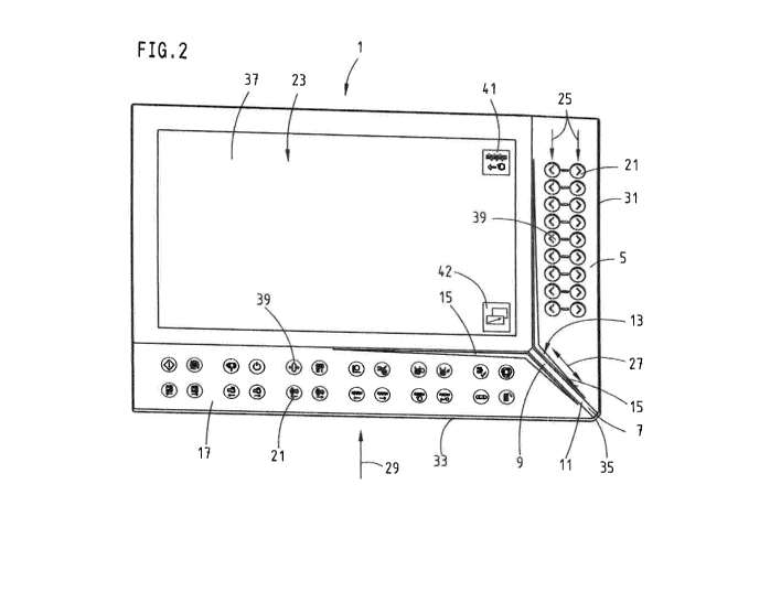
The Figures show a human-machine interface 1 in the form of different views.
In the
following, reference is made to the Figures equally unless something to the
contrary is
mentioned.
The human-machine interface 1 serves for the interactive control of a machine
that is not
illustrated in detail but is merely symbolized by means of the reference
symbol 3. In the
case of the machine 3, this is, in particular, an injection moulding machine
for the
processing of synthetic materials and other plasticizable materials such as
for instance
powdery or ceramic masses. In particular, the injection moulding machine
comprises at
least one plasticizing unit and a mould closure unit and preferably a
plurality of moveable
and adjustable components the location of which can be controlled manually or
adjusted
by appropriate operator input at the human-machine interface 1. To this end,
the human-
machine interface 1 comprises a regulating input unit 5 that is arranged on a
right-hand
edge 31 as well as an input unit 17 that is arranged on a lower edge 33. A
selection input
unit 42 is formed by assignable keys on the screen itself. The regulating
input unit 5 and
the input unit 17 are arranged above a corner 35 along the edges 31 and 33 of
the
human-machine interface 1. Hereby, they are arranged adjacent to each other at
the
corner 35 in the manner of a mitre joint, whereby a free space is left between
them.
A parameter input unit 7 is arranged in the free space remaining between the
regulating
input unit 5 and the input unit 17. The parameter input unit 7 comprises a
surface 11
which fills up the free space remaining between the input unit 17 and the
regulating input
unit 5. The surface 11 is in the form of a touch-sensitive surface, i.e. it
reacts to contacts
made by an operator of the human-machine interface 1. The surface 11 is
therefore part
CA 03040976 2019-04-17
- 12 -
of the parameter input unit 7, whereby, in like manner to the process of
adjusting a slider,
stroking the strip-like surface 11 makes for an intuitive adjustment process
for regulating
the speed of a regulating function of the machine 3.
Herein, a parameter is to be understood as meaning the parameters which can be
.. entered for operating an injection moulding machine. These are pressure,
the speed of a
movement, temperature, time points such as for instance switchover time points
between
the injection and dwell pressure phase, the time points for operating the
ejector, partial
cycle times e.g. in the case of multi-component injection processes, path-
information for
the mould closing unit, mould height, dosage and injection amount, flow rate,
the quantity
of addable components and much more besides, i.e. the usual factors relevant
to a
specialist in injection moulding machines. The preferred field of employment
of the
invention thus lies in those areas in which mutually dependent parameters are
to be
entered.
The human-machine interface 1 likewise comprises in the free space a
longitudinally
extending or strip-like parameter display unit 9. The parameter input unit 7
and the
parameter display unit 9 are arranged together, predominantly one above the
other
between the regulating input unit 5 and the input unit 17. The e.g. speed of
movement of
the components of an injection moulding machine can be entered and indicated
thereby.
The parameter display unit 9 comprises a bar graph indicator 13, preferably
incorporating
a plurality of light segments which are depicted exemplarily in Fig. 2. A
higher or lower
regulating speed of the regulating function can be symbolized in dependence on
the
number of segments of the bar graph indicator 13 that are illuminated. The bar
graph
indicator 13 preferably follows a process of stroking the surface 11 of the
parameter input
unit 7. As an alternative, however, it is also conceivable that a regulating
parameter
actually occurring in the machine 3 be reported back by means of the bar graph
indicator
13. The feedback of the regulating parameters is advantageously effected
simultaneously
with the touching of the surface 11 and/or the actually occurring regulating
parameter, i.e.
the actual process of adjusting a regulating speed serving as a regulating
parameter, for
example.
As can be perceived in Figs. la and 2, an illuminated readout 15 is arranged
on each side
of the parameter display unit 9, in particular on each side of the bar graph
indicator 13.
Starting from the corner 35, the illuminated readout 15 extends along the
longitudinal
extent of the free space or of the parameter display unit 9 arranged therein
and spreads
CA 03040976 2019-04-17
- 13 -
out in the shape of a Y at an internal end of the parameter display unit 9. It
extends, in
particular, in the shape of a Y in parallel along the input unit 17 and the
regulating input
unit 5.
Feedback of a state of the machine 3 can be effected simultaneously with the
interactive
.. process of controlling the machine 3 by means of the illuminated readout
15. This can be
effected by modulating the illuminated readout, in particular by altering a
colour of the
illuminated readout 15. An operator of the human-machine interface 1 can thus
always be
kept informed about the state of the machine 3, in particular in regard to the
currently
occurring manually controlled regulating function.
.. Moreover, the human-machine interface 1 comprises a touch-sensitive screen
23 that is
visible in Figs. 1a and 2. The regulating input unit 5 and the input unit 17
are arranged on
two adjoining sides of the screen 23 neighbouring the screen 23 or along the
sides. The
screen 23 can be implemented as a so-called touch screen, in particular, one
having
multiple-touch capability, i.e. where a plurality of points is activated at
the same time.
Preferably, a touch-sensitive surface 37 of the screen 23 extends over the
regulating
input unit 5 and the input unit 17. Thus, for example, the surface 11 can be
provided for
the operation of the parameter input unit 7. In accordance with an
alternative, however,
the surface 11 could also comprise a separate device for detecting contacts
and the
regulating input unit 5 and/or the input unit 17 can be conventional or
separate keys.
Both the input unit 17 and the regulating input unit 5 comprise a plurality of
operating
elements 21 that are provided physically fixed. Preferably, these comprise
transparent
cylinders, preferably glass cylinders 19. The glass cylinders can be formed
from any
transparent material such as glass, acrylic glass, another transparent
synthetic material
and/or the like. Preferably, the surface 37 and the glass cylinders 19
comprise identical
materials.
The operating elements 21 of the input unit 17 have different pictograms 39
for
symbolizing a regulating function of the machine 3 that is selectable thereby
and are
preferably permanently assigned to these functions. For example, there is a
pictogram for
symbolizing a screw movement of a plasticising unit of the machine 3. Pressing
or
actuating the appropriate operating element 21 leads to two adjacently located
operating
elements 21 of the regulating input unit 5 being enabled for the corresponding
regulating
function, i.e. adjustment of the screw. Certain regulating inputs or operating
elements 21
of the regulating input unit 5 can be selected for the further operation by at
least one
CA 03040976 2019-04-17
- 14 -
selection input unit 42 that is representable on the screen 23 - only one
symbol for this is
illustrated in the exemplary embodiment but there could be more.
In a preferred alternative, a symbol 41 such as e.g. a split symbol which
signifies a
functional assignment of the operating elements 21 such as, for example, the
directions of
the screw movement, appears on the touch-sensitive screen beside the operating
elements 21 of the regulating input unit 5. The description of the screw
movement is
exemplary and can be used in analogous manner for every possible regulating
function of
the machine 3, an injection moulding machine in the exemplary embodiment.
It is apparent that the input unit 17 and/or the selection input unit 42 also
comprise
significantly more operating elements 21 than regulating functions that can be
manually
controlled at the same time by means of the regulating input unit 5.
Nevertheless, in order
to enable all the regulating functions to be controlled, the operating
elements 21 of the
regulating input unit 5 are dynamically assigned as described above, i.e. are
characterised by one of the symbols 41 as necessary, or are re-enabled for
assignment to
.. a further regulating function after being re-actuated and/or after the
passage of a certain
period of time and/or in accordance with some other condition.
Thus, for the purposes of controlling a regulating function of the machine 3,
a selection
input 29 is firstly effected at one of the operating elements 21 of the
selection input unit
42. In like manner, however, an input can be effected by means of one of the
operating
elements 21 of the input unit 17 that is permanently assigned to a function.
As a reaction
thereto, two operating elements 21 of the regulating input unit 5 are enabled,
i.e. they are
dynamically assigned and are characterised by the symbol 41 for the selected
regulating
function on the touch-sensitive screen 23. After the selection of the
regulating function
has been effected, it can be manually controlled by a regulating input 25 at
the two
operating elements 21 of the regulating input unit 5, in particular,
bidirectionally, as is
preferably symbolized by the arrow symbols on the operating elements 21.
During the process of operating the regulating input unit 5, e.g. the
regulating speed of
the correspondingly selected regulating function, i.e. the screw movement for
example,
can be simultaneously adjusted by a process of stroking the surface 11 on the
parameter
input unit 7. The description of the speed of the screw movement as a
parameter is
exemplary and can be utilised in analogous manner for every possible
regulating function
of the parameters of the machine 3. Moreover, the display of the regulating
speed that
CA 03040976 2019-04-17
- 15 -
has been entered or selected is likewise effected simultaneously by means of
the
parameter display unit 9. The process of entering the regulating speed is
effected by
means of a parameter input 27, in particular, a bidirectional process of
stroking the
surface 11. The inputs 25 to 29 are symbolized by means of arrows in Fig. 2.
As can be perceived in Figs. 1 b, 3 and 4a, the human-machine interface 1
comprises a
mounting console 43. The mounting console 43 comprises a mounting surface 45
which
is arranged at an acute angle to the surface 37 of the screen 23. It is
thereby possible to
attach the human-machine interface 1 to a vertical wall of the machine 3 or to
a stand on
the machine in such a way that the screen 23 is inclined relative to the
vertical. The
ergonomics and, in particular, the processes of reading from and/or making an
entry on
the human-machine interface 1 can thus be improved. In particular, observation
and
reading off the human-machine interface 1 at an angle from above can be
facilitated. As
can be perceived in Figs. lb and 4a, the mounting surface 45 comprises borings
47 for
mounting purposes and a through hole 49 for making contact with the machine 3.
Moreover, for the purposes of improving the ergonomics, the regulating input
unit 5 and/or
the input unit 17 are inclined at least slightly with respect to the surface
37 of the screen
23, as can be perceived particularly well from the detail depicted in Fig. 4b.
The surface
37 and the input units 17 and/or 5 are arranged at an obtuse angle 51 to each
other. As
seen in one direction of observation 53, which is symbolized in Figs. 4a and
4b by means
of an arrow, the input units 5 and/or 17 are inclined away from the operator
of the human-
machine interface 1. In relation to an operator, the regulating input unit 5
and/or the input
unit 17 are inclined away therefrom, in particular, at an obtuse angle of e.g.
between 180
and 150 degrees, preferably, about 179 to 175 degrees. Due to this
inclination, on the
one hand, comfortable handling is made possible when operating the laterally
arranged
input units. Moreover, any possible faulty operations occurring thereby when
using the
touch-sensitive screen, by an arm of the operator for example, can be avoided
since it is
inclined away from the arm of the operator and cannot therefore be
inadvertently touched
thereby.
In the following, a method of interactively controlling the machine 3 by means
of the
human-machine interface us described in more detail with reference to Fig. 2:
CA 03040976 2019-04-17
- 16 -
The regulating input unit 5, the parameter input unit 7 and the parameter
display unit 9
are provided by the human-machine interface 1. The manual regulating input 25
for
manually controlling the regulating function of the machine 3 is then
detected. The
parameter input 27 is detected simultaneously whereby, likewise
simultaneously, the
regulating parameter such as a regulating speed that is optically perceptible
to the
operator of the human-machine interface 1 by means of the parameter display
unit 9 is
fed back. Preferably, the process of detecting the manual selection input 29
for selecting
the regulating function at the provided selection input unit 42 has been
effected
beforehand. As a reaction to or in dependence on the selection input 29, the
regulating
input unit 5 is enabled. It is only then that detection of the manual
regulating input 25 can
be effected. In accordance with a preferred alternative, it is conceivable for
the selection
input 29 to likewise be fed back or acknowledged. This is conceivable, in
particular, by
backlighting the relevant operating element 21 to different levels of
brightness. For
example, after being operated, the operating element 21 of the input unit 17
or the
selection input unit 42 can be backlit at maximum brightness. Selectable
operating
elements 21 or regulating functions controllable thereby can be backlit at
medium
brightness. Non-selectable regulating functions i.e. regulating functions that
are not
available in the machine 3 cannot be backlit or can only be backlit to a
weaker level of
backlighting e.g. at the input unit 17.
.. In accordance with a further alternative, feedback of the enabling process
and/or the
selected regulating function is also effected at the regulating input unit 5.
This is likewise
effected, if necessary, by means of backlighting, in particular, raising the
brightness of the
relevant operating elements 21 and/or by means of the symbol 41 illustrated on
the
screen 23. The selected regulating function can be visualized by means of the
symbol 41.
Detection of the manual regulating input by means of the corresponding
operating
elements 21 of the regulating input unit 5 can be effected in corresponding
manner. The
operating elements 21 of the regulating input unit 5 are thus dynamically
assigned in
dependence on the selection input 29 at the regulating input unit 5.
The illuminated readout 15 and/or the parameter display unit 9 have a Y-shape
which
tapers in the direction of corner 35, whereby an intuitive operation and/or
setting of the
regulating parameters is assisted or becomes possible. The parameter input
unit 7 forms
a slider for adjusting parameters such as pressure, temperature, time points
such as e.g.
switching times between an injection process and a dwell pressure phase, time
points for
operating the ejector, partial cycle times e.g. in the case of multi-component
injection
CA 03040976 2019-04-17
- 17 -
processes, path information for the mould closing unit, the mould height,
dosage and
injection amount, the flow rate, the quantity of mixable components and much
more
besides, in particular, for adjusting and/or reducing the axle speeds of the
regulating
function or the machine 3. Advantageously, a parameter value that is to be
adjusted can
.. be effected almost steplessly or in a plurality of individual steps by
simply pushing or
sliding a finger over the surface 11 that is preferably implemented as a glass
surface. In
particular, the actually set parameter value i.e. the currently set regulating
speed for
example is visualized by means of the bar graph indicator 13 which comprises
in
particular a plurality of individual LEDs, in particular, in the form of a
distinctive arrow in
order to aid intuitive detection of the regulating parameter. The current
state of the
machine 3 can always be represented by modulating the illuminated readout 15
and/or
the bar graph indicator 13, in particular, by means of appropriate colours.
The operating elements 21 are advantageously implemented such as to be
discoverable
in tactile manner, in particular, by means of glass cylinders 19. For example,
the
regulating functions ejector-forwards and ejector-back can thereby be realized
immediately after a corresponding selection input 29 has been enabled. The
corresponding triggering device or push-button is the glass cylinder 19 which
is preferably
fitted closely into and flush with a panel of the human-machine interface 1,
whereby both
the stroke-length and force-path characteristic of a typical key or a push-
button are
capable of being simulated by an actuation process. Due to the flush, close-
fitting
installation and the choice of material, the glass of the key cylinder i.e.
the glass cylinder
19, simple cleaning of the regulating input unit 5, the input unit 17 and/or
the entire
human-machine interface 1 is possible. The operating elements 21 and in
particular their
glass cylinders 19 preferably contain one of the pictograms 39 and are
preferably backlit
at a plurality of brightness levels, e.g. for symbolizing a selection state
and/or that it is
available for operation. In particular, operating elements 21 that are
operable for a user
prompting system can be illuminated, whereas not currently operable ones are
darkened.
The input unit 17 which is implemented as a keyboard strip for example
preferably
comprises all of the essential functions for the operation of an injection
moulding machine
and also a corresponding plurality of pictograms 39 which are arranged in
fixed locations
on the human-machine interface 1, i.e. are re-findable at any time in an
optimal way.
Operating elements 21 or keys having a switching function such as drives-
on/off, can
symbolize their state of actuation, in particular, by a backlight system
incorporating
different levels of brightness.
CA 03040976 2019-04-17
- 18 -
The regulating input unit 5 which is likewise preferably implemented as a
keyboard strip
comprises freely assignable operating elements 21 or keys. In particular, the
operating
elements 21 exhibit arrow symbols which can symbolize a direction of the
regulating
parameters that are manually controllable thereby. In addition, the symbols 41
for
indicating the respective function of the operating elements 21 which are
arranged
alongside them to the right as viewed in the direction of Fig. 2 are
illustrated on the
screen 23. In particular, the touch-sensitive screen 23 is implemented as a
high-resolution
multi-touch screen. The respective symbol 41 may be split as necessary in
order to
additionally symbolize the directions of the regulating function.
It is particularly preferred that the regulating input unit 5 and/or input
unit 17 be connected
directly to a control system of the machine 3 by means of a real-time
interface which is
not illustrated in more detail in the Figures. They are thereby independent of
a computing
or data processing device of the human-machine interface 1. The regulating
input unit
and/or the input unit is thereby not effective on the HMI PC, but is
operatively connected
directly to the machine control system by a synchronous serial interface. It
is thus
possible to have a direct feedback between the nominal value and the actual
value via the
parameter display unit 9 and a parameterisation process in real time.
As is perceivable in Fig. 3, the entire human-machine interface 1 or the
surface 37 of the
screen 23 can be inclined to the machine 3 or can be attached to a pictorially
not
illustrated stand, in particular, at an angle of between 10 and 20 degrees and
especially
15 degrees to the vertical. The ergonomics for the workstations can thereby be
optimized.
Furthermore, the human-machine interface 1 can be adaptable to operators of
differing
heights by a vertical adjustment process. Moreover, as is apparent from Fig.
4b, the
regulating input unit 5 and/or the input unit 17 are slightly inclined to the
rear and together
with the contra-directional inclination of a housing of the human-machine
interface 1
facilitate the operation of the individual operating elements 21 or keys and
the surface 11
of the parameter input unit 7.
In the concrete preferred exemplary embodiment, a function for driving an axle
can be
implemented directly by actuating a permanently assigned operating element 21
in the
input field 17 e.g. the key "screw forwards". Hereby, some of these keys are
direct driving
keys, i.e. a direct (manually operated) movement is effected upon the
actuation thereof. In
the automatic cycle state, however, actuation of this key is blocked since an
actuating
action is not plausible, this being visualized by the absence of backlighting.
In the manual
CA 03040976 2019-04-17
- 19 -
operational state, the operating elements 21 are unblocked, backlit, and are
backlit yet
more brightly upon actuation. In the input field 17, the essential keys for
the injection
moulding machine are permanently assigned so that operation without on-screen
navigation is possible.
It is self-evident that this description can be subjected to the most diverse
modifications,
changes and adaptations which fall within the range of equivalents to the
accompanying
claims.
CA 03040976 2019-04-17
- 20 -
List of reference numerals
1 human-machine interface
3 machine
regulating input unit
5 7 parameter input unit
9 parameter display unit
11 surface
13 bar graph indicator
illuminated readout
10 17 input unit
19 glass cylinder
21 operating element
23 screen
regulating input
15 27 parameter input
29 selection input
31 right-hand edge
33 lower edge
corner
20 37 surface
39 pictograms
41 symbol
42 selection input unit
43 mounting console
25 45 mounting surface
47 boring
49 through hole
51 angle
53 direction of view