Note: Descriptions are shown in the official language in which they were submitted.
Catheter arrangement and method for producing such a
catheter arrangement
[0001] The invention relates to a catheter arrangement
comprising a catheter tube with at least one lumen,
wherein the lumen has a proximal end and a distal end,
and at least one supply line, wherein the supply line
has a distal end and a proximal end, and wherein the
distal end of the supply line is connected in a fluid-
conducting manner to the proximal end of the lumen.
[0002] The invention also relates to a method for
producing such a catheter arrangement.
[0003] A catheter arrangement of this type is
generally known in the sphere of medical technology and
is provided in the form of a multi-lumen venous
catheter for use in infusion and/or transfusion
therapy. The known catheter arrangement has a catheter
tube, through which a first lumen and a second lumen,
which each have a distal end and a proximal end, are
extended. The distal ends of the lumina are arranged in
a portion of the catheter tube that, in a correctly
applied state of the catheter arrangement, is
introduced into, for example, a patient's vein. By
contrast, in the applied state of the catheter
arrangement, the proximal ends of the lumina are
arranged outside the patient's body. Furthermore, a
first supply line and a second supply line each having
a proximal end and a distal end are provided. The first
supply line is assigned to the first lumen. The second
supply line is assigned to the second lumen. The
proximal ends of the supply lines can each be provided
in a basically known manner with a connection element
CA 3040990 2019-04-24
- 2 -
for the fluid-conducting connection to an infusion
container or the like. The distal ends of the supply
lines are connected in a fluid-conducting manner to the
proximal end of the respectively assigned lumen. Two
channels which are separate from each other are thereby
formed. Said channels extend from the proximal end of
the respective supply line as far as the distal end of
the lumen assigned to the respective supply line. The
channels of the catheter arrangement that are separated
from each other in such a manner permit, for example,
simultaneous administration of incompatible medical
fluids, with mixing of the fluids within the catheter
arrangement being avoided.
[0004] In addition, the known catheter arrangement has
a connecting unit, which is manufactured as a plastics
injection-moulded component, for the fluid-conducting
connection of the supply lines to the respective lumen.
Said connecting unit is also referred to as a channel
separator. The connecting unit is arranged between the
distal ends of the supply lines and the proximal ends
of the lumina and is injection moulded both onto the
supply lines and onto the catheter tube. The connecting
unit has two connecting channels which are arranged
next to each other and are extended separately from
each other. The distal ends of the supply lines and the
proximal ends of the lumina lead on opposite end sides
of the connecting unit into the connecting channels.
The connecting channels to this extent each form a
fluid-guiding portion of the channels, which are
separate from each other, of the catheter arrangement.
[0005] In order to produce the known catheter
arrangement, a supporting element in the form of what
is referred to as an insert-moulding needle is in each
CA 3040990 2019-04-24
- 3 -
case introduced into the proximal end of the first
lumen and into the proximal end of the second lumen.
Furthermore, the supply lines are pushed at their
respective distal end onto the insert-moulding needle
of the respectively assigned lumen, wherein the distal
ends of the supply lines and the proximal ends of the
lumina are spaced apart from one another. Furthermore,
the arrangement in such a way is placed into an
injection mould and insert moulded in the region of the
insert-moulding needles with a thermoplastic. The
insert-moulding needles are subsequently removed and
the connecting unit formed in such a manner is removed
from the injection mould. The insert-moulding needles
serve firstly for supporting the lumina and the supply
lines since they would otherwise collapse during the
plastics injection moulding because of pressure.
Secondly, the insert-moulding needles form negative
shapes for the respective connecting channel which
extends between the distal end of the supply line and
the proximal end of the assigned lumen.
[0006] During the production of the connecting unit by
means of plastics injection moulding, manufacturing
errors, for example shrinkage cavities, stress cracks
or an incomplete formation, can occur. As a result,
leakages in the fluid-conducting connections between
the distal ends of the supply lines and the proximal
ends of the lumina or an undesirable fluid-conducting
transverse connection between the connection channels
of the connecting unit can occur.
[0007] It is the object of the invention to provide a
catheter arrangement of the type mentioned at the
beginning and a method for producing such a catheter
arrangement, the catheter arrangement and method having
CA 3040990 2019-04-24
- 4 -
improved properties in relation to the prior art.
[0008] This object is achieved for the catheter
arrangement in that the fluid-conducting connection
between the supply line and the lumen is brought about
by means of a fluid-tight joining connection between
the distal end of the supply line and the proximal end
of the lumen. By means of the solution according to the
invention, a direct fluid-conducting connection between
the supply line and the lumen is achieved. Accordingly,
an otherwise customary, additional connecting unit can
be dispensed with. The disadvantages and risks
associated with such a connecting unit, in particular
the formation of leakages or transverse connections
between the connecting channels due to defective
manufacturing, can to this extent be avoided. The
fluid-tight joining connection can be designed in
particular as a press connection, plug-in connection,
screw connection, adhesive connection and/or welded
connection between the distal end of the supply line
and the proximal end of the lumen. For example, the
distal end of the supply line can be plugged, pressed
or screwed into the proximal end of the assigned lumen,
or vice versa. Alternatively or additionally, the
distal end of the supply line can be adhesively bonded
and/or welded to the proximal end of the lumen. The
fluid-tight joining connection is
preferably
nondetachable. Within the context of the invention,
"proximal" denotes a position facing away from a
catheter tip of the catheter arrangement. By contrast,
"distal" refers to a position facing the catheter tip.
[0009] The solution according to the invention is
suitable in a particularly preferred manner for a
multi-lumen catheter arrangement having two or more
CA 3040990 2019-04-24
- 5 -
lumina and accordingly two or more supply lines which
are each assigned to one of the lumina. However, the
solution according to the invention is not restricted
to such multi-lumen catheter arrangements, but can also
be used in a single-lumen catheter arrangement having
just one lumen and one supply line.
[0010] In a refinement of the invention, the distal
end of the supply line is plugged, in particular in a
fluid-tight manner, into the proximal end of the lumen.
If two lumina and two supply lines are provided, a
first plug-in connection is formed between the first
supply line and the first lumen and/or a second plug-in
connection is formed between the second supply line and
the second lumen. Said plug-in connections can be
designed as such in a fluid-tight manner, for example
by means of a corresponding adaptation of the outer
diameters of the supply lines to the inner diameters of
the lumina, thus resulting in each case in a fluid-
tight press fit. Alternatively, the plug-in connections
can be formed in a fluid-tight manner only to a limited
extent, if at all, with it being possible for the
distal ends of the supply lines to be welded and/or
adhesively bonded in a fluid-tight manner to the
proximal end of the respective lumen in order to form
the fluid-tightness of the joining connection. The same
applies if just one plug-in connection is provided in a
single-lumen catheter arrangement.
[0011] In a further refinement of the invention, the
distal end of the supply line has an introducing
portion which is integrally formed on the end side and
is formed in a complementary manner with respect to a
receiving portion, which is integrally formed on the
end side, of the proximal end of the lumen. The
CA 3040990 2019-04-24
- 6 -
introducing portion of the supply line is integrally
formed on the end side of the distal end and can be
designed in particular as a pin, collar or nipple. The
receiving portion is integrally formed at the proximal
end of the lumen and can be designed in particular in
the manner of a sleeve or by means of a radial
expansion of the lumen. The introducing portion is
preferably integrally formed in one piece on the supply
line. Accordingly, it is advantageous if the receiving
portion is integrally formed in one piece on the
catheter tube or on the lumen.
[0012] In a further refinement of the invention, the
receiving portion is expanded, in particular thermally,
in relation to a flow cross section of the lumen. A
flow cross section of the lumen should be understood as
meaning a cross section which is provided for guiding
fluid. The flow cross section can be in particular
round, oval, circular, semi-circular or sickle-shaped.
The receiving portion can be formed in particular by
means of pressing a suitable tool into the proximal
ends of the lumen. If a multi-lumen catheter
arrangement having at least two lumina and at least two
supply lines is provided, the flow cross sections and
therefore the receiving portions can be formed
differently.
[0013] In a further refinement of the invention, the
joining connection is welded, in particular in a fluid-
tight manner. Accordingly, the joining connection
between the distal end of the supply line and the
proximal end of the lumen has a welded connection. The
welded connection can be designed as such in a fluid-
tight manner. For example, the distal end of the supply
lines can be "butt-welded" to the proximal end of the
CA 3040990 2019-04-24
- 7 -
lumen. Alternatively, the fluid-tight joining
connection can have a plug-in connection in accordance
with the statements above, with the welded connection
additionally being provided. Both the supply line and
the catheter tube are preferably manufactured from
plastic at least in the region of the joining
connection. The plastics composition of the supply
lines here is coordinated with the plastics composition
of the catheter tube in such a manner that they can be
joined together by means of basically known plastics
welding methods.
[0014] In a further refinement of the invention, a
capsule unit is provided which is manufactured as a
low-pressure injection moulded component made from
plastic and is configured and/or arranged in such a
manner that the region of the fluid-tight joining
connection between the supply line and the lumen is
encapsulated by means of the capsule unit. Manufactured
as a low-pressure injection moulded component means
that the capsule unit is produced using a manufacturing
method primarily known up to now in the field of
electrical engineering and which is also referred to as
low-pressure moulding. The capsule unit surrounds the
fluid-tight joining connection between the supply line
and the lumen in the manner of a covering, a sheathing
or a housing. The capsule unit preferably has at one
end a conically formed contact portion which, in a
correctly applied state of the catheter arrangement, is
provided for contact with an entry point of the
catheter tube on the patient. In addition, it is
advantageous if the capsule unit has fixing portions by
means of which the capsule unit and therefore the
catheter arrangement can be fastened on the patient in
CA 3040990 2019-04-24
- 8 -
a basically known manner.
[0015] In a further refinement of the invention, the
capsule unit brings about an additional fluid sealing
and/or tensile force relief of the fluid-tight joining
connection. The fluid sealing brought about by means of
the capsule unit is to this extent redundant.
Accordingly, a leakage of the catheter arrangement can
be avoided in the event of an unintentional detaching
of the fluid-tight joining connection between the
distal end of the supply line and the proximal end of
the lumen. By means of this refinement of the
invention, a particularly reliable sealing of the
connection between the supply line and the catheter
tube is accordingly achieved. If the capsule unit is
manufactured as a low-pressure injection moulded
component, said capsule unit is connected fixedly, in
particular in an integrally bonded manner, to the
supply line and to the catheter tube. A tensile force
relief of the fluid-tight joining connection is thereby
achieved. Accordingly, an undesirable detaching of the
fluid-tight joining connection can be counteracted by
means of the capsule unit. This is a particularly
robust and patient-safe configuration of the invention.
[0016] In a further refinement of the invention, the
capsule unit is manufactured from hot-melt adhesive, in
particular from polyamide or polyolefin. Hot-melt
adhesives are basically known as such and have a
thermoplastic composition. Hot-melt adhesives are
preferably suitable for processing by means of low-
pressure injection moulding since they have a
comparatively low viscosity in the molten state. This
makes it possible for processing to take place at low
pressures - in comparison to conventional plastics
CA 3040990 2019-04-24
- 9 -
injection moulding. A pressure-induced deformation of
the fluid-tight joining connection during the formation
of the capsule unit can thereby be avoided.
[0017] In a further refinement of the invention, the
catheter arrangement is a central venous catheter
arrangement or a peripherally inserted catheter
arrangement or a midline catheter arrangement.
[0018] The object on which the invention is based is
achieved for a method of the type mentioned at the
beginning in that a step is provided: joining the
distal end of the supply line together with the
proximal end of the lumen in a fluid-tight manner. By
means of the solution according to the invention, a
complicated and potentially error-prone production of
the fluid-tight connection by means of an otherwise
customary connecting unit can be dispensed with.
Instead, the distal end of the supply line is joined,
preferably directly, together with the proximal end of
the lumen, for example by means of a press connection,
plug-in connection, screw connection, adhesively
bonding connection and/or welded
connection.
Accordingly, for the production of a multi-lumen
catheter arrangement, the distal end of the respective
supply line is joined together with the proximal end of
the respective lumen in a fluid-tight manner.
[0019] In a further refinement of the invention, the
method has a step: integrally forming an end-side
introducing portion on the distal end of the supply
line. The integral forming of the introducing portion
preferably takes place by means of deformation of the
distal end of the supply line. The introducing portion
is preferably integrally formed here in a complementary
CA 3040990 2019-04-24
- 10 -
manner to a cross-sectional shape of the lumen, for
example in a round, oval, circular or semi-circular,
crescent-shaped or sickle-shaped manner. Such integral
forming of the introducing portion permits a simple and
accurately fitting joining of the supply line together
with the lumen.
[0020] In a further refinement of the invention, the
method has a step: integrally forming an end-side
receiving portion on the proximal end of the lumen by
means of radial expansion of the lumen. The receiving
portion is preferably integrally formed on the proximal
end of the lumen by means of deformation. For example,
a correspondingly configured tool in the form of a
mandrel, a pin or the like can be pressed into the
proximal end of the lumen such that the latter is
plastically radially expanded. The receiving portion is
preferably shaped substantially conically. If the
supply line is provided with a corresponding
introducing portion, it is advantageous if the
configuration of the receiving portion is coordinated
with the configuration of the introducing portion in
such a manner that a transition fit or press fit arises
therebetween.
[002].] In a further refinement of the invention, the
integral forming of the introducing portion and/or of
the receiving portion takes place by means of
deformation under the action of pressure and/or heat.
Both the supply line and the catheter tube are
preferably manufactured from thermoplastic.
Thermoplastics soften under the action of heat and, in
a softened state, are deformable by application of
comparatively small pressure or deformation forces.
This configuration of the invention permits the
CA 3040990 2019-04-24
- 11 -
introducing and/or receiving portions to be able to be
produced particularly simply and cost-effectively.
[0022] In a further refinement of the invention,
during the joining together in a fluid-tight manner the
introducing portion of the supply line is plugged into
the receiving portion of the lumen. Accordingly, a
direct force- and/or form-fitting connection is
produced between the distal ends of the supply line and
the proximal end of the lumen. The fluid tightness of
the joining connection can already be brought about
here by plugging of the introducing portion into the
receiving portion as such. For example, by the outer
contour of the introducing portion being coordinated
with the inner contour of the receiving portion in such
a manner that a press fit between the supply line and
the respective lumen, and therefore fluid tightness,
results. Alternatively, or additionally, after the
introducing portion is plugged into the receiving
portion, the fluid tightness of the joining connection
can be brought about by means of further method steps,
for example adhesive bonding, welding or the like.
[0023] In a further refinement of the invention,
during the joining together in a fluid-tight manner,
the distal end of the supply line is welded to the
proximal end of the lumen, in particular the
introducing portion is welded to the receiving portion.
If the supply line and the catheter tube are
manufactured from thermoplastic, the distal end of the
supply line can be connected to the proximal end of the
lumen by means of basically known plastics welding
methods, for example by means of circular welding,
laser transmission welding, induction welding or
ultrasonic welding.
CA 3040990 2019-04-24
- 12 -
[0024] In a further refinement of the invention, the
method has a step: testing, in particular by means of
computer-aided image recognition and image processing,
an assignment of the introducing portion to the
receiving portion and/or an assignment of the distal
end of the supply line to the proximal ends of the
lumen. In order to be able to ensure detection and/or
identification of the respective portions and/or ends
by means of computer-aided image processing, it is
advantageous if the portions and/or the ends are
provided with corresponding marking elements, for
example a coloured and/or graphical marking. Testing by
means of computer-aided image processing means that, in
order to avoid a defective assignment of the portions
and/or ends and therefore for quality assurance, use is
made of a method which is basically known as such in
the sphere of automation technology and which is also
referred to as machine vision or image understanding.
Such testing of the assignment of the portions and/or
of the ends can take place in particular during the
production of a multi-lumen catheter arrangement, for
example before the introducing portions are plugged
into the respective receiving portion. Alternatively or
additionally, the testing of the assignment can take
place before the welding of the supply lines to the
catheter tube or of the introducing portions to the
respective receiving portion. In addition, it is
advantageous if, during the testing, the tightness of
the joining connection between the distal end of the
respective supply line and the proximal end of the
respective lumen is also checked. For this purpose, the
computer-aided image recognition and image processing
can be configured in such a manner that a defect at the
joining connection, for example an incompletely formed
CA 3040990 2019-04-24
- 13 -
welded connection, can be detected.
[0025] In a further refinement of the invention, the
method has a step: encapsulating the fluid-tight
joining connection between the supply line and the
lumen by means of low-pressure plastics injection
moulding, with a capsule unit being formed. Low-
pressure plastics injection moulding is basically known
in particular in the sphere of producing electric
and/or electronic components. It is also referred to as
low-pressure moulding. In this method, a thermoplastic
hot-melt adhesive, for example polyamide or polyolefin,
is liquefied under the action of heat. For example, the
hot-melt adhesive is heated to a temperature of 180 C
to 240 C, preferably 210 C. The hot-melt adhesive
liquefied in such a manner is pressed into a
corresponding injection mould at a comparatively low
pressure, preferably within the range of 3.5 bar to 14
bar. On account of such low injection pressures, low-
pressure moulding is preferably suitable for
encapsulating sensitive components which could be
deformed and/or damaged under the action of relatively
high pressures, such as prevail, for example, during
conventional plastics injection moulding. Accordingly,
an otherwise customary supporting of the lumen and of
the supply line by means of what is referred to as an
insert-moulding needle can be dispensed with. This
refinement of the invention makes it possible in
particular to achieve improved sealing of the fluid-
tight joining connection and tensile force relief
between the supply line and the catheter tube.
[0026] Further advantages and features of the
invention emerge from the claims and from the
description below of preferred exemplary embodiments of
CA 3040990 2019-04-24
- 14 -
the invention that are illustrated with reference to
the drawings.
Figure 1 shows, in a schematic illustration, an
embodiment of a catheter arrangement
according to the invention comprising a
catheter tube and two catheter supply lines,
Figure 2 shows, in a schematic cross-
sectional
illustration, the catheter tube of the
catheter arrangement along an intersecting
line A-A according to Figure 1,
Figure 3 shows, in a schematic longitudinal sectional
illustration, the catheter
arrangement
according to Figures 1 and 2 in the region of
a fluid-tight joining connection between the
supply lines and the lumen of the catheter
tube,
Figure 4 shows, in a schematic
perspective
illustration, a proximal region of the
catheter tube of the catheter arrangement
according to Figures 1 to 3,
Figure 5 shows, in a schematic
perspective
illustration, a distal region of one of the
supply lines of the catheter arrangement
according to Figures 1 to 4,
Figure 6 shows, in a schematic flow illustration, an
embodiment of a method according to the
invention for producing the catheter
arrangement according to Figures 1 to 5,
Figure 7 shows, in a schematic flow illustration,
CA 3040990 2019-04-24
- 15 -
details of a method step of the method
according to Figure 6,
Figure 8 shows, in a schematic flow illustration,
details of a further method step of the
method according to Figure 6, and
Figure 9 shows, in a schematic flow illustration,
details of a further method step of the
method according to Figure 6.
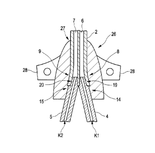
[0027] A catheter arrangement 1 according to Figure 1
is provided for use in infusion therapy. The catheter
arrangement 1 is designed in the form of a two-lumen
central venous catheter arrangement. Irrespective
thereof, the solution according to the invention can,
of course, also be used in the case of single-lumen,
three-lumen or multi-lumen catheter arrangements and is
not restricted to central venous catheter arrangements,
but rather in particular can also be used in a
peripherally inserted catheter arrangement or a midline
catheter arrangement.
[0028] The catheter arrangement 1 has a catheter tube
2 with a catheter tip 3 and two catheter supply lines
4, 5 which are referred to below as first supply line 4
and second supply line 5. Both the catheter tube 2 and
the supply lines 4, 5 are manufactured from plastic and
are flexurally flexible. As is apparent in particular
with reference to Figure 2, the catheter tube 2 has a
first lumen 6 and a second lumen 7. The lumina 6, 7
extend separated from each other through the catheter
tube 2 and each have a proximal end 8, 9 (Figure 3) and
a distal end 10, 11. The distal end 10 of the first
lumen 6 leads into an outlet opening 12 of the catheter
CA 3040990 2019-04-24
- 16 -
tip 3. The distal end 11 of the second lumen 7 leads
into a radial opening 13 of the catheter tube 2.
Furthermore, the supply lines 4, 5 each have a distal
end 14, 15 (Figure 3) and a proximal end 16, 17. Both
the proximal end 16 of the first supply line 4 and the
proximal end 17 of the second supply line 5 are
provided with a respective connection element 18. The
connection elements 18 are each provided for the fluid-
conducting connection of the supply lines 4, 5 to an
infusion system (not specifically apparent), in
particular an infusion container or the like. For this
purpose, the connection elements 18 can each be
provided with a Luer connection which is known as such.
As is apparent with reference to Figure 3, the distal
end 14 of the first supply line 4 is connected in a
fluid-conducting manner to the proximal end 8 of the
first lumen 6 and the distal end 15 of the second
supply line 5 is connected in a fluid-conducting manner
to the proximal end 9 of the second lumen 7. Two
channels Kl, K2 which are separate from each other are
thereby formed. The channels Kl, K2 extend from the
proximal end 16, 17 of the respective supply line 4, 5
as far as the distal end 10, 11 of the lumen 6, 7
assigned to the respective supply line 4, 5. This
permits, for example, a simultaneous administration of
incompatible medicinal fluids by means of the catheter
arrangement 1, with mixing of the fluids within the
catheter arrangement 1 being avoided.
[0029] As is furthermore apparent in particular with
reference to Figure 3, the fluid-conducting connections
between the supply lines 4, 5 and the lumina 6, 7 are
brought about by means of a respective fluid-tight
joining connection 19, 20 between the distal end 14, 15
CA 3040990 2019-04-24
- 17 -
of the respective supply line 4, 5 and the proximal end
8, 9 of the respective lumen 6, 7. For this purpose,
the distal end 14 of the first supply line 4 is plugged
into the proximal end 8 of the first lumen 6, and the
distal end 15 of the second supply line 5 is plugged
into the proximal end 9 of the second lumen 7. The
plug-in connections between the supply lines 4, 5 and
the respective lumen 6, 7 are configured here in such a
manner that the joining connections 19, 20 are fluid-
tight. For this purpose, a press fit is in each case
provided between the distal ends 14, 15 of the supply
lines 4, 5 and the respective proximal end 8, 9 of the
lumina 6, 7.
[0030] Further details of the fluid-tight joining
connections 19, 20 are apparent in particular with
reference to Figures 4 and 5. As is apparent with
reference to Figure 4, a receiving portion 21, 22 is in
each case integrally formed on the end side of the
proximal ends 8, 9 of the lumina 6, 7. In comparison to
Figure 2, it is apparent that the receiving portions
21, 22 are radially expanded in relation to a flow
cross section D1, D2 of the respective lumen 6, 7. In
addition, the distal ends 14, 15 of the supply lines 4,
5 are each provided with an introducing portion.
Figure 5 shows the first supply line 4 provided with an
introducing portion 23. The second supply line 5 is
configured in a corresponding manner in the region of
its distal end 15, and therefore only the introducing
portion 23 of the first supply line 4 will be described
in detail with reference to Figure 5 in order to avoid
repetitions. The introducing portion 23 is integrally
formed on the end side of the distal end 14 of the
first supply line 4 and is configured in a
CA 3040990 2019-04-24
- 18 -
complementary manner with respect to the receiving
portion 21 of the proximal end 8 of the first lumen 6.
In this respect, the introducing portion 23 has a
conical outer contour and, in addition, is offset
radially in relation to a circumferential surface 24 of
the first supply line 4 such that a radial collar 25 is
arranged between the introducing portion 23 and the
further axial profile of the first supply line 4.
However, said radial collar 25 does not absolutely have
to be present. Instead, the region can be configured,
for example, conically or cylindrically. It can be seen
with reference to Figure 3 that the distal end 14 of
the first supply line 4 is plugged into the proximal
end 9 of the first lumen 6 in such a manner that the
radial collar 25 comes into contact on the end side of
the catheter tube 2, and therefore the supply line 4 is
fixed in the axial direction in relation to the
catheter tube 2. The same applies here to the plug-in
connection between the second supply line 5 and the
second lumen 7, but this does not necessarily have to
be the case.
[0031] The receiving portions 21, 22 are designed here
in the form of an inner cone in each case, wherein the
cross sections of the receiving portions 21, 22
correspond in their basic shape to the flow cross
sections D1, D2 and in this respect are of circular
design. Of course, it is also possible for a differing
configuration of the flow cross sections and of the
receiving portions to be provided. For example, the
flow cross sections of the lumina can be configured in
an oval, semi-circular, crescent-shaped or sickle-
shaped manner. In such a case, the receiving portions
have an accordingly designed shape. In such a case, the
CA 3040990 2019-04-24
- 19 -
introducing portions of the supply lines are
accordingly also adapted in their shape.
[0032] The above-described plug-in connections between
the supply lines 4, 5 and the respective lumen 6, 7 are
designed here in a fluid-tight manner as such, and
therefore the fluid tightness of the joining
connections 19, 20 is already produced by the
configuration of said plug-in connections. The joining
connections 19, 20 are additionally welded. Should the
plug-in connections between the supply lines 4, 5 and
the respective lumen 6, 7 not already be designed in a
fluid-tight manner as such, the fluid tightness of the
joining connections 19, 20 can also be brought about
solely by welding of the distal ends 14, 15 of the
supply lines 4, 5 to the proximal end 8, 9 of the
respective lumen 6, 7.
[0033] As is furthermore apparent with reference to
Figure 1, the catheter arrangement 1 also has a capsule
unit 26. The capsule unit 26 is manufactured as a low-
pressure injection moulded component made from plastic
and is configured and/or arranged in such a manner that
the region of the fluid-tight joining connections 19,
20 between the supply lines 4, 5 and the lumina 6, 7 is
encapsulated by means of the capsule unit 26. This is
also apparent with reference to Figure 3. The capsule
unit 26 as such does not form a fluid-guiding portion
of the channels Kl, K2. Instead, the capsule unit 26
brings about an additional fluid sealing of the fluid-
tight joining connections 19, 20. In addition, a
tensile force relief of the fluid-tight joining
connections 19, 20 is brought about by means of the
capsule unit 26, by the capsule unit 26 firstly being
fixedly connected to the supply lines 4, 5 and secondly
CA 3040990 2019-04-24
- 20 -
being fixedly connected to the catheter tube 2. The
capsule unit 26 is manufactured from a hot-melt
adhesive. Hot-melt adhesives which can be processed by
means of low-pressure injection moulding are basically
known. For example, polyamide or polyolefin can be used
as the hot-melt adhesive. As is furthermore apparent
with reference to Figure 1 and Figure 3, the capsule
unit 26 has a contact portion 27 which has a
substantially conical basic shape. In a correctly
applied state of the catheter arrangement 1, the
contact portion 27 is provided to enter into contact
with an entry point of the catheter tube 2 on the
patient. As a result of the conical configuration of
the contact portion 27, bleeding at the above-described
entry point of the catheter tube 2 can be counteracted.
In addition, the capsule unit 26 has two fixing
portions 28. The fixing portions 28 are arranged on
opposite sides of the capsule unit 26. The capsule unit
and therefore the catheter arrangement 1 can be fixed
on the patient in a basically known manner by means of
the fixing portions 28.
[0034] An embodiment of a method according to the
invention according to Figures 6 to 9 is provided for
producing a catheter arrangement 1 according to
Figures 1 to 5. The method is based here on the fact
that both the supply lines 4, 5 and the catheter tube 2
are present in the form of basically known plastics
semi-finished products.
[0035] The method first of all provides a step: (A)
integrally forming an end-side introducing portion (23,
cf. Figure 5) in each case on the distal end 14 of the
first supply line 4 and on the distal end 15 of the
second supply line 5.
CA 3040990 2019-04-24
- 21 -
[0036] The method then provides a further step: (B)
integrally forming an end-side receiving portion (21,
22, cf. Figure 4) in each case on the proximal end 8 of
the first lumen 6 and on the proximal end 9 of the
second lumen 7 by means of radial expansion of the
first lumen 6 and of the second lumen 7.
[0037] The method then provides a further step: (C)
joining the distal ends 14, 15 of the supply lines 4, 5
together with the proximal end 8, 9 of the respective
lumen 6, 7 in a fluid-tight manner. In this step, the
distal end 14 of the first supply line 4 is joined
together with the proximal end 8 of the first lumen in
a fluid-tight manner and the distal end 15 of the
second supply line 5 is joined together with the
proximal end 9 of the second lumen 7 in a fluid-tight
manner. If the lumina 6, 7 are provided at their
proximal ends 8, 9 with a respective receiving portion
21, 22 and the supply lines 4, 5 are each provided at
their distal ends 14, 15 with an introducing portion -
but this is not absolutely necessary - in this step the
receiving portions 21, 22 are joined together with the
introducing portion of the respective lumen 6, 7 in a
fluid-tight manner.
[0038] Furthermore, temporally before and/or after the
fluid-tight joining together (C), the method provides a
step: (P) testing an assignment of the introducing
portions (23, cf. Figure 5) to the receiving portions
21, 22 and/or an assignment of the distal ends 14, 15
of the supply lines 4, 5 to the proximal ends 8, 9 of
the lumina 6, 7. It is tested in this step whether the
first supply line 4 is assigned to the first lumen 6
and the second supply line 5 to the second lumen 7. An
erroneous assignment which may lead, for example, to an
CA 3040990 2019-04-24
- 22 -
impairment of the function of the catheter arrangement
1 or to leakiness of the fluid-tight joining
connections 19, 20 is thereby avoided. The testing step
(P) provides the use of a basically known method of
computer-aided image recognition and image processing,
which is also referred to as mechanical vision or image
understanding.
[0039] After the fluid-tight joining together (C) or
optionally the testing (P), the method provides a
further step: (V) encapsulating the fluid-tight joining
connections 19, 20 between the supply lines 4, 5 and
the lumina 6, 7 by means of low-pressure plastics
injection moulding, with a capsule unit (26, cf.
Figures 1, 3) being formed.
[0040] Further details of the method according to
Figure 6 are apparent with reference to Figures 7 to 9.
Said figures refer to details of the above-described
steps (A), (B), (C) and (V) of the method and also
clarify said details illustratively with reference to a
further embodiment of a catheter arrangement according
to the invention. This catheter
arrangement
substantially corresponds to the embodiment described
previously with reference to Figures 1 to 5. The
catheter arrangement which is apparent at any rate in
regions with reference to Figures 7 to 9 essentially
differs from the catheter arrangement 1 according to
Figures 1 to 5 in that this catheter arrangement has
three lumina and in this respect is provided with three
supply lines and three lumina instead of with two
supply lines and two lumina (cf. Figure 1). In order to
avoid repetitions, reference is therefore made to the
disclosure with regard to the embodiment according to
Figures 1 to 5. Functionally identical and/or
CA 3040990 2019-04-24
- 23 -
structurally identical portions and parts of the
catheter arrangement apparent at any rate in regions
with reference to Figures 7 to 9 are provided with the
same reference signs with the addition of the letter a.
[0041] Details of the integrally forming method step
(A) are apparent with reference to Figure 7. In a first
partial step (Al), a supply line 4a is pressed with its
distal end 14a into a mould 40 under the action of
pressure - which is intended to be clarified by means
of the arrow F. The mould 40 has a conical mould
contour and is heated, which is intended to be
clarified with reference to the arrows W. The distal
end 14a is supported on its inner diameter by means of
a mandrel 50. The mandrel 50 prevents the supply line
4a from being closed on the end side as it is being
pressed into the mould 40.
[0042] In a further partial step (A2), the distal end
14a of the supply line 4a is pressed into the mould 40
in such a manner that it comes into contact on the end
side with the bottom region of the mould 40. In
addition, the supply line 4a is rotated about its
longitudinal axis and the action of heat W is
maintained. An introducing portion 23a is thereby
formed at the distal end 14a of the supply line 4a.
[0043] In a further partial step (A3), the supply line
4a is demoulded in the axial direction from the mould
40. This is clarified with reference to the arrow F'.
[0044] Depending on the number of provided supply
lines, the above-described partial steps (Al - A3) are
repeated for each of the provided supply lines.
[0045] Further details of the integrally forming step
CA 3040990 2019-04-24
- 24 -
(B) of the method according to Figure 6 are clarified
with reference to Figure 8. A first partial step (B1)
makes provision for the proximal end of a catheter tube
2a, which is configured with three lumina, to be
clamped in a mould 60 having two partial halves. The
clamping movement of the two partial halves of the
mould 60 is intended to be clarified with reference to
the arrows S. In addition, the mould 60 is under the
action of heat W. The catheter tube 2a is thereby
softened in the region of clamping between the two
partial halves. In an upper region with respect to the
plane of the drawing of Figure 8, the mould 60 has a
conical expansion, and therefore the catheter tube 2a
is first of all spaced apart from the mould 60 in this
region. Furthermore, the partial step (B1) makes
provision for a punching tool 70 to be pressed in the
axial direction into the proximal ends of the lumina
(not denoted specifically) of the catheter tube 2a. The
punching tool 70 is provided on the end sides with
conically configured pins which, during the axial
movement of the punching tool 70, enter the proximal
ends of the lumina and thereby expand the latter in the
radial direction.
[0046] In a further partial step (B2), the punching
tool 70 is completely moved downward in the axial
direction, with the end-side pins of the punching tool
70 completely entering the proximal ends of the lumina
of the catheter tube 2a. Receiving portions which are
not apparent specifically (cf. Figures 4, 21, 22) are
thereby formed at the proximal ends of the lumina.
[0047] In a further partial step which is not apparent
specifically, the punching tool 70 is moved upward in
the axial direction and the catheter tube 2a is
CA 3040990 2019-04-24
- 25 -
unclamped from the two partial halves of the mould 60
and removed from the mould 60 for further handling.
[0048] During the fluid-tight joining together (C),
the introducing portions formed in such a manner are
then plugged into the receiving portions of the lumina
(Cl) and welded to one another (C2), which is clarified
schematically with reference to Figure 6.
[0049] Further details of the encapsulating step (V)
of the method according to Figure 6 are apparent with
reference to Figure 9. In a first partial step (V1),
the catheter tube 2a is placed together with the first
supply line 4a, a second supply line 5a and a further
third supply line (not denoted specifically) into a
lower partial half 80 of a low-pressure injection
mould. In this state, fluid-tight joining connections
19a, 20a between the distal ends of the respective
supply lines 4a, 5a and the proximal end of the
respective lumen of the catheter tube 2a are already
formed. The same applies to the third supply line (not
denoted specifically) which is joined together with the
proximal end of the lumen, assigned thereto, of the
catheter tube 2a in a likewise fluid-tight manner. As
is apparent with reference to Figure 6, in order to
form the fluid-tight joining connections 19a, 20a, the
supply lines 4a, 5a are plugged into the respective
lumen of the catheter tube 2a (Cl) and/or are welded to
said lumen (C2). The position of the catheter tube 2a
and of the supply lines 4a, 5a and of the further
supply line (not denoted specifically) is fixed in
relation to the lower partial half 80 of the low-
pressure injection mould by means of clamping jaws 90.
This is clarified with reference to the arrows L.
CA 3040990 2019-04-24
- 26 -
[0050] In a further partial step (V2), it is provided
that an upper partial half 81 of the low-pressure
injection mould is lowered onto the lower partial half
80, which is clarified with reference to the arrow M,
with the low-pressure injection mould being completely
closed. The partial halves 80, 81 here form a negative
shape N of a capsule unit, which is not apparent
specifically (cf. Figures 1, 26). After the complete
closing of the two partial halves 80, 81, the negative
shape N is filled in a basically known manner with
molten hot-melt adhesive under pressurization within a
range of approximately 3.5 bar - 14 bar. A capsule unit
encapsulating the fluid-tight joining connections 19a,
20a between the supply lines 4a, 5a and the lumina of
the catheter tube 2a is thereby formed.
[0051] In a further partial step (V3) (cf. Figure 6),
the capsule unit formed in such a manner is demoulded
in a basically known manner from between the partial
halves 80, 81 of the low-pressure injection mould, and
the catheter arrangement is removed.
CA 3040990 2019-04-24