Note: Descriptions are shown in the official language in which they were submitted.
1
GREENHOUSE DESICCANT DEHUMIDIFIER AND CARBON DIOXIDE GENERATOR
TECHNICAL FIELD
This invention relates generally to greenhouses and more particularly to a
greenhouse
desiccant dehumidifier and carbon dioxide generator.
BACKGROUND OF THE INVENTION
Greenhouses are utilized in many geographical locations to grow crops and
plants year-
round and in climates that may not otherwise provide hospitable growing
conditions.
Greenhouses typically consist of structures that enable environmental
conditions inside the
structure to be regulated and controlled. For example, it is usually desirable
to have higher carbon
dioxide (CO2) levels within a greenhouse to increase yield. Maintaining high
carbon dioxide
levels within a greenhouse, however, typically causes excessive amounts of
heat and moisture
within the greenhouse.
SUMMARY OF THE INVENTION
According to embodiments of the present disclosure, disadvantages and problems
associated with previous greenhouse systems may be reduced or eliminated.
Certain exemplary embodiments can provide a dehumidification system,
comprising: an
enclosure comprising: a process airflow inlet and a process airflow outlet; a
reactivation airflow
inlet and a reactivation airflow outlet; a carbon dioxide airflow inlet and a
carbon dioxide airflow
outlet, wherein each of the process airflow inlet, the process airflow outlet,
and the carbon dioxide
airflow outlet is configured to be separately coupled to a greenhouse via one
of a plurality of
ducts; a desiccant; a primary heat exchanger; a secondary heat exchanger
coupled to the primary
heat exchanger; a first fan configured to generate a carbon dioxide airflow
through the primary
heat exchanger and the secondary heat exchanger, the carbon dioxide airflow
entering the
enclosure through the carbon dioxide airflow inlet and exiting the enclosure
through the carbon
dioxide airflow outlet; a burner configured to generate a flame into one end
of the primary heat
exchanger, the flame configured to increase an amount of carbon dioxide within
the carbon
dioxide airflow; a second fan configured to generate a reactivation airflow
that flows over a
CA 3040998 2019-04-24
2
portion of the secondary heat exchanger, a portion of the primary heat
exchanger, and then
through a first portion of the desiccant in order to dry the desiccant, the
reactivation airflow
entering the enclosure through the reactivation airflow inlet and exiting the
enclosure through the
reactivation airflow outlet a third fan configured to generate a process
airflow that flows through
.. a second portion of the desiccant in order to provide dehumidification to
the process airflow, the
process airflow entering the enclosure through the process airflow inlet and
exiting the enclosure
through the process airflow outlet.
Certain exemplary embodiments can provide a dehumidification system,
comprising: a
desiccant; a primary heat exchanger; a secondary heat exchanger; a first fan
configured to
.. generate a carbon dioxide airflow through the primary heat exchanger and
the secondary heat
exchanger; a burner configured to generate a flame into one end of the primary
heat exchanger,
the flame configured to increase an amount of carbon dioxide within the carbon
dioxide airflow;
a second fan configured to generate a reactivation airflow that flows over a
portion of the
secondary heat exchanger, a portion of the primary heat exchanger, and then
through a first
portion of the desiccant in order to dry the desiccant; and a third fan
configured to generate a
process airflow that flows through a second portion of the desiccant in order
to provide
dehumidification to the process airflow.
Certain exemplary embodiments can provide a system, comprising: a desiccant; a
heat
exchanger; a first fan configured to generate a first airflow through the heat
exchanger; a burner
.. configured to generate a flame into one end of the heat exchanger, the
flame configured to
increase an amount of carbon dioxide within the first airflow; and a second
fan configured to
generate a reactivation airflow that flows over a portion of the heat
exchanger and then through
a first portion of the desiccant in order to dry the desiccant; wherein the
first fan is further
configured to pass the first airflow through a second portion of the desiccant
after the first airflow
exits the heat exchanger in order to provide dehumidification to the first
airflow.
In some embodiments, a dehumidification system includes a desiccant, a primary
heat
exchanger, a secondary heat exchanger, three fans, and a burner. The first fan
generates a carbon
dioxide airflow through the primary heat exchanger and the secondary heat
exchanger. The
burner generates a flame into one end of the primary heat exchanger. The flame
increases an
amount of carbon dioxide within the carbon dioxide airflow. The second fan
generates a
CA 3040998 2019-04-24
3
reactivation airflow that flows over a portion of the secondary heat
exchanger, a portion of the
primary heat exchanger, and then through a first portion of the desiccant in
order to dry the
desiccant. The third fan generates a process airflow that flows through a
second portion of the
desiccant in order to provide dehumidification to the process airflow.
Certain embodiments of the present disclosure may provide one or more
technical
advantages. Some embodiments provide a greenhouse desiccant dehumidifier and
carbon
dioxide generator that may be used by greenhouses to increase the amount of
carbon dioxide
within the greenhouse while simultaneously providing dehumidification and
cooling to the
greenhouse. To accomplish this, embodiments of the disclosure include one or
more heat
exchangers, a fuel burner, and a desiccant. A first heated airflow from the
fuel burner is directed
through the one or more heat exchangers to transfer heat to a second airflow
flowing over the one
or more heat exchangers. This cools the first airflow and condenses water
vapor within the first
airflow into liquid water, but does not affect the carbon dioxide content of
the first airflow. The
cooled, less moist first airflow with its increased carbon dioxide content may
then be introduced
into a greenhouse. This allows the greenhouse to have increased carbon dioxide
levels while
maintaining desired humidity and temperature levels within the greenhouse. The
second airflow,
after being heated by the one or more heat exchangers, is then passed through
a portion of the
desiccant to regenerate the desiccant. After passing through the desiccant,
the second airflow
may be directed outdoors. A third airflow is taken from the interior of the
greenhouse, passed
through another portion of the desiccant, and then returned to the greenhouse.
The desiccant
absorbs water vapor from the third airflow, thereby further dehumidifying the
greenhouse.
Certain embodiments of the present disclosure may include some, all, or none
of the above
advantages. One or more other technical advantages may be readily apparent to
those skilled in
the art from the figures, descriptions, and claims included herein.
BRIEF DESCRIPTION OF THE DRAWINGS
To provide a more complete understanding of the present invention and the
features and
advantages thereof, reference is made to the following description taken in
conjunction with the
accompanying drawings, in which:
FIGURE 1 illustrates a greenhouse system, according to certain embodiments;
CA 3040998 2019-04-24
4
FIGURE 2 illustrates a desiccant dehumidifier and carbon dioxide generator
that may be
utilized by the greenhouse system of FIGURE 1, according to certain
embodiments; and
FIGURE 3 illustrates another configuration of a desiccant dehumidifier and
carbon
dioxide generator that may be utilized by the greenhouse system of FIGURE 1,
according to
certain embodiments.
DETAILED DESCRIPTION OF THE DRAWINGS
Greenhouses are utilized in many geographical locations to grow crops and
plants year-
round and in climates that may not otherwise provide hospitable growing
conditions.
Greenhouses typically consist of structures that enable environmental
conditions inside the
structure to be regulated and controlled. For example, it is usually desirable
to have higher carbon
dioxide (CO2) levels within a greenhouse to increase yield. Maintaining high
carbon dioxide
levels within a greenhouse, however, typically causes excessive amounts of
heat and moisture
within the greenhouse. For example, some greenhouses utilize fuel burners to
generate and
introduce additional carbon dioxide into the greenhouse. The carbon dioxide is
consumed by
plants within the greenhouse and helps to increase yield. In addition to
carbon dioxide, fuel
burners introduce additional heat and water vapor, which may be undesirable in
greenhouses.
The additional heat may cause the greenhouse to overheat and the additional
water vapor may
increase the humidity within the greenhouse to levels that cause damage to the
plants and/or the
greenhouse itself.
To address these and other problems and inefficiencies of existing greenhouse
systems,
the disclosed embodiments provide a greenhouse desiccant dehumidifier and
carbon dioxide
generator that may be used by greenhouses to increase the amount of carbon
dioxide within the
greenhouse while simultaneously providing dehumidification and cooling to the
greenhouse. To
accomplish this, embodiments of the disclosure include one or more heat
exchangers, a fuel
burner, and a desiccant. A first heated airflow from the fuel burner is
directed through the one
or more heat exchangers to transfer heat to a second airflow flowing over the
one or more heat
exchangers. This cools the first airflow and condenses water vapor within the
first airflow into
liquid water, but does not affect the carbon dioxide content of the first
airflow. The cooled, less
moist first airflow with its increased carbon dioxide content may then be
introduced into a
CA 3040998 2019-04-24
_
greenhouse. This allows the greenhouse to have increased carbon dioxide levels
while
maintaining desired humidity and temperature levels within the greenhouse. The
second airflow,
after being heated by the one or more heat exchangers, is then passed through
a portion of the
desiccant to regenerate the desiccant. After passing through the desiccant,
the second airflow
5 may be directed outdoors. A third airflow is taken from the interior of
the greenhouse, passed
through another portion of the desiccant, and then returned to the greenhouse.
The desiccant
absorbs water vapor from the third airflow, thereby further dehumidifying the
greenhouse.
The advantages and features of certain embodiments are discussed in more
detail below
in reference to FIGURES 1-3. FIGURE 1 illustrates a greenhouse system, FIGURE
2 illustrates
a desiccant dehumidifier and carbon dioxide generator that may be utilized by
the greenhouse
system of FIGURE 1, and FIGURE 3 illustrates another configuration of a
desiccant dehumidifier
and carbon dioxide generator that may be utilized by the greenhouse system of
FIGURE 1,
according to certain embodiments.
FIGURE 1 illustrates a greenhouse system 100, according to certain
embodiments. As
illustrated in FIGURE 1, greenhouse system 100 may include a greenhouse 120
and a desiccant
dehumidifier and carbon dioxide generator 110. In some embodiments, desiccant
dehumidifier
and carbon dioxide generator 110 may be located in an outdoor environment 160
(i.e., outside of
greenhouse 120). In other embodiments, desiccant dehumidifier and carbon
dioxide generator
110 may be installed within greenhouse 120 (e.g., within a wall of greenhouse
120). In some
embodiments, desiccant dehumidifier and carbon dioxide generator 110 may be
physically
connected to greenhouse 120 via one or more ducts 130. Ducts 130 may be used
to circulate a
process airflow 140 through desiccant dehumidifier and carbon dioxide
generator 110 and back
into greenhouse 120. In addition, a duct 130 may be used to transport a carbon
dioxide airflow
170 from desiccant dehumidifier and carbon dioxide generator 110 into
greenhouse 120. In
embodiments where desiccant dehumidifier and carbon dioxide generator 110 is
installed within
greenhouse 120, process airflow 140 and reactivation airflow 150 may flow
directly between
desiccant dehumidifier and carbon dioxide generator 110 and greenhouse 120
without any ducts
130.
In general, desiccant dehumidifier and carbon dioxide generator 110 provides
beneficial
carbon dioxide to greenhouse 120 while simultaneously providing
dehumidification and cooling
CA 3040998 2019-04-24
6
to greenhouse 120. To accomplish this, desiccant dehumidifier and carbon
dioxide generator 110
includes three airflows: process airflow 140, reactivation airflow 150, and
carbon dioxide airflow
170. A first airflow, carbon dioxide airflow 170, flows from outdoor
environment 160 and into
a fuel burner where it is heated and its carbon dioxide content is increased.
Carbon dioxide
airflow 170 then flows through one or more heat exchangers in order to
transfer heat to a second
airflow, reactivation airflow 150, that is flowing over the one or more heat
exchangers. This
cools carbon dioxide airflow 170 and condenses water vapor within carbon
dioxide airflow 170
into liquid water but does not affect the carbon dioxide content of carbon
dioxide airflow 170.
The cooled, drier carbon dioxide airflow 170 with its increased carbon dioxide
content may then
be introduced into greenhouse 120. This allows greenhouse 120 to have
increased carbon dioxide
levels while maintaining desired humidity and temperature levels within the
greenhouse.
Reactivation airflow 150, after being heated by the one or more heat
exchangers, is then passed
through a portion of a desiccant within desiccant dehumidifier and carbon
dioxide generator 110
in order to dry and regenerate the desiccant. After passing through the
desiccant, reactivation
airflow 150 may then be directed back into outdoor environment 160. A third
airflow, process
airflow 140, is taken from the interior of greenhouse 120, passed through
another portion of the
desiccant, and then returned to greenhouse 120. The desiccant absorbs water
vapor from process
airflow 140, thereby further dehumidifying greenhouse 120. As a result, the
operation and
maintenance of greenhouse 120 may be more cost and energy efficient while the
yield of
greenhouse 120 may be increased.
The heating portion of desiccant dehumidifier and carbon dioxide generator 110
generally
has a different goal than a typical condensing furnace or boiler. Desiccant
dehumidifier and
carbon dioxide generator 110 converts a flow of atmospheric air (e.g., carbon
dioxide airflow
170) into a flow with higher concentration of carbon dioxide using a
combustion burner (e.g.,
burner 240). A goal of desiccant dehumidifier and carbon dioxide generator 110
is to cool this
airflow in order to condense and remove as much water vapor from it as
possible as well as
reducing the amount of combustion heat added to the greenhouse. In addition,
desiccant
dehumidifier and carbon dioxide generator 110 may be configured to provide a
very hot airflow
(e.g., reactivation airflow 150) to a desiccant media (e.g., desiccant 210) in
order to regenerate
the desiccant.
CA 3040998 2019-04-24
7
Greenhouse 120 is any enclosure that is used to grow plants. In general,
greenhouse 120
is used to maintain certain environmental conditions to support plant growth.
For example, the
temperature, humidity, and levels of carbon dioxide within greenhouse 120 may
be maintained
to certain levels to provide essential conditions to support plant growth. In
some embodiments,
greenhouse 120 may be ventilated to outside environment 160. For example, some
greenhouses
120 may utilize an exhaust fan to ventilate excess heat and moisture from the
greenhouse to
outside environment 160 via greenhouse ventilation airflow 180.
While some embodiments have been described as being utilized by greenhouse
120, the
disclosed embodiments may be utilized by any other enclosed space. The
disclosed embodiments
are not limited to being used only with greenhouses such as greenhouse 120.
Any space that
needs increased carbon dioxide levels along with lower humidity and cooler
temperatures may
benefit from desiccant dehumidifier and carbon dioxide generator 110.
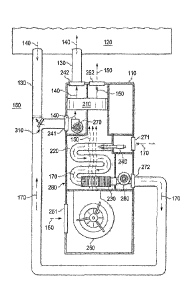
FIGURE 2 illustrates a desiccant dehumidifier and carbon dioxide generator 110
that may
be utilized with greenhouse system 100, according to certain embodiments. In
some
embodiments, desiccant dehumidifier and carbon dioxide generator 110 includes
a desiccant 210,
a primary heat exchanger 220, a secondary heat exchanger 230, a burner 240,
and three fans:
reactivation fan 250, combustion fan 260, and process airflow fan 270. In some
embodiments,
desiccant dehumidifier and carbon dioxide generator 110 may be packaged within
an enclosure
280, which may be any appropriate shape or size. In some embodiments,
enclosure 280 includes
a process airflow inlet 241, a process airflow outlet 242, a reactivation
airflow inlet 251, a
reactivation airflow outlet 252, a carbon dioxide airflow inlet 271, and a
carbon dioxide airflow
outlet 272. Inlets 241, 251, and 271 and outlets 242, 252, and 272 may be any
appropriate shape
and size and may be in any appropriate location on enclosure 280. In some
embodiments, inlets
241, 251, and 271 and outlets 242, 252, and 272 are suitably shaped and sized
to accommodate
ducts 130. In some embodiments, reactivation airflow inlet 251 and carbon
dioxide airflow inlet
271 may be combined into a single inlet of desiccant dehumidifier and carbon
dioxide generator
110 since they are both inlets for airflows from outdoor environment 160.
In general, desiccant 210 is made of any appropriate solid or liquid material
(e.g.,
activated alumina, silica gel, molecular sieve, etc.) that is capable of
absorbing water vapor from
process airflow 140, thereby providing dehumidification to process airflow
140. In some
CA 3040998 2019-04-24
8
embodiments, desiccant 210 is wheel-shaped and rotates in either a clockwise
or counter-
clockwise motion when viewed from above. In embodiments that rotate, an
electric motor (not
illustrated) may be provided within desiccant dehumidifier and carbon dioxide
generator 110 to
cause desiccant 210 to rotate. This shape allows one portion of desiccant 210
(e.g., one side of
the desiccant wheel) to be within process airflow 140 and another portion
(e.g., the opposite side
of the desiccant wheel) to be within reactivation airflow 150 at the same
time. In some
embodiments, for example, half of desiccant 210 may be within process airflow
140 while the
other half is within reactivation airflow 150. The rotation of desiccant 210
permits desiccant 210
to provide continuous dehumidification to process airflow 140 since portions
that absorb moisture
.. are then rotated to reactivation airflow 150 where they are dried and then
returned to process
airflow 140.
Primary heat exchanger 220 and secondary heat exchanger 230 are each devices
that
transfer heat between carbon dioxide airflow 170 and reactivation airflow 150.
Primary heat
exchanger 220 and secondary heat exchanger 230 may be any type of heat
exchanger such as a
shell and tube heat exchanger, a plate heat exchanger, a plate and shell heat
exchanger, a plate
fin heat exchanger, a direct contact heat exchanger, a microchannel heat
exchanger, and the like.
In some embodiments, one end of primary heat exchanger 220 is coupled to
burner 240 and the
other end of primary heat exchanger 220 is coupled to secondary heat exchanger
230 as illustrated
in FIGURE 2. In these embodiments, burner 240 introduces a flame into one end
of primary heat
exchanger 220, which heats carbon dioxide airflow 170 as it travels into
primary heat exchanger
220. Carbon dioxide airflow 170 flows through primary heat exchanger 220, into
secondary heat
exchanger 230, and then ultimately out of desiccant dehumidifier and carbon
dioxide generator
110 via carbon dioxide airflow outlet 272. In other embodiments, however, only
a single heat
exchanger may be utilized by desiccant dehumidifier and carbon dioxide
generator 110. In these
embodiments, burner 240 introduces a flame into one end of the single heat
exchanger (e.g.,
primary heat exchanger 220), which heats carbon dioxide airflow 170 as it
travels into the single
heat exchanger. Carbon dioxide airflow 170 flows through the single heat
exchanger and then
ultimately out of desiccant dehumidifier and carbon dioxide generator 110 via
carbon dioxide
airflow outlet 272.
CA 3040998 2019-04-24
9
Burner 240 is any appropriate device that introduces a flame into carbon
dioxide airflow
170. In some embodiments, burner 240 is a fuel burner that burns propane,
natural gas, diesel,
kerosene, or any other appropriate fuel. In some embodiments, burner 240 is an
indirect-fired
burner. In general, burner 240 heats carbon dioxide airflow 170 as it enters
primary heat
exchanger 220 and increases the carbon dioxide content of carbon dioxide
airflow 170.
Fans 250, 260, and 270 may be any type of air mover (e.g., axial fan, forward
inclined
impeller, backward inclined impeller, etc.) that is configured to generate
reactivation airflow 150,
carbon dioxide airflow 170, and process airflow 140, respectively. In some
embodiments, fans
250, 260, and 270 are variable-speed fans.
Fans 250, 260, and 270 may be located in any appropriate location within
desiccant
dehumidifier and carbon dioxide generator 110. In some embodiments, fans 250,
260, and 270
may be located proximate to inlets 251, 271, and 241, respectively, either
inside or outside of
desiccant dehumidifier and carbon dioxide generator 110. In other embodiments,
fans 250, 260,
and 270 may be located proximate to outlets 252, 272, and 242, respectively,
either inside or
outside of desiccant dehumidifier and carbon dioxide generator 110. In some
embodiments, fans
250, 260, and 270 may not be included within or coupled to desiccant
dehumidifier and carbon
dioxide generator 110 at all. For example, process airflow fan 270 may be
external to desiccant
dehumidifier and carbon dioxide generator 110 (e.g., within a duct 130 or
greenhouse 120).
Furthermore, fans 250, 260, and 270 may be configured to generate airflows
150, 170, and 140,
respectively, in any appropriate direction through desiccant dehumidifier and
carbon dioxide
generator 110. For example, process airflow 140 and reactivation airflow 150
may be in a
counterflow arrangement in some embodiments.
In operation, desiccant dehumidifier and carbon dioxide generator 110 provides
beneficial
carbon dioxide to greenhouse 120 while simultaneously providing
dehumidification and cooling
to greenhouse 120. In some embodiments, carbon dioxide airflow 170 is drawn
from outdoor
environment 160 (or from greenhouse 120 in some embodiments) into desiccant
dehumidifier
and carbon dioxide generator 110 by combustion fan 260 through carbon dioxide
airflow inlet
271 where it first flows into burner 240. Burner 240 heats carbon dioxide
airflow 170 and
increases the carbon dioxide content of carbon dioxide airflow 170. Carbon
dioxide airflow 170
then flows through primary heat exchanger 220 and secondary heat exchanger 230
(or
CA 3040998 2019-04-24
10
alternatively a single heat exchanger) in order to transfer heat from carbon
dioxide airflow 170
to reactivation airflow 150 that is flowing over primary heat exchanger 220
and secondary heat
exchanger 230. This cools carbon dioxide airflow 170 and condenses water vapor
within carbon
dioxide airflow 170 into liquid water but does not affect the carbon dioxide
content of carbon
dioxide airflow 170. The condensed water from carbon dioxide airflow 170 may
then be drained
out of desiccant dehumidifier and carbon dioxide generator 110. The cooled,
drier carbon dioxide
airflow 170 with its increased carbon dioxide content may then exit desiccant
dehumidifier and
carbon dioxide generator 110 via carbon dioxide airflow outlet 272 and be
directed into
greenhouse 120 via, for example, duct 130. This allows greenhouse 120 to have
increased carbon
dioxide levels while maintaining desired humidity and temperature levels
within the greenhouse.
Reactivation airflow 150, which is drawn into desiccant dehumidifier and
carbon dioxide
generator 110 via reactivation fan 250 through reactivation airflow inlet 251,
flows over and is
heated by secondary heat exchanger 230 and primary heat exchanger 220. After
being heated by
secondary heat exchanger 230 and primary heat exchanger 220, reactivation
airflow 150 flows
through a portion of desiccant 210 in order to regenerate desiccant 210. After
passing through
desiccant 210, reactivation airflow 150 may then be directed back into outdoor
environment 160
via reactivation airflow outlet 252.
Process airflow 140 is drawn from the interior of greenhouse 120 and into
desiccant
dehumidifier and carbon dioxide generator 110 through process airflow inlet
241 via process
airflow fan 270. Process airflow 140 passes through a different portion of
desiccant 210 from
reactivation airflow 150, exits desiccant dehumidifier and carbon dioxide
generator 110 via
process airflow outlet 242, and is directed back to greenhouse 120 via, for
example, a duct 130.
Desiccant 210 absorbs water vapor from process airflow 140, thereby further
dehumidifying
greenhouse 120. As a result, the operation and maintenance of greenhouse 120
may be more cost
and energy efficient while the yield of greenhouse 120 may be increased.
In some embodiments, fans 250, 260, and 270 may be automatically
enabled/disabled
based on conditions within greenhouse 120. For example, when the humidity
within greenhouse
120 reaches or exceeds a predetermined amount (e.g., 90% humidity as detected
by a humidistat
within greenhouse 120 or desiccant dehumidifier and carbon dioxide generator
110), fans 250,
260, and 270 may be enabled to generate airflows 140, 150, and 170 in order to
transfer moisture
CA 3040998 2019-04-24
11
out of greenhouse 120 to outside environment 160. When the humidity within
greenhouse 120
is below the predetermined amount, fans 250, 260, and 270 may be disabled to
conserve energy.
As another example, when the temperature within greenhouse 120 reaches or
exceeds a
predetermined amount (e.g., 100 degrees F as detected by a thermostat within
greenhouse 120 or
desiccant dehumidifier and carbon dioxide generator 110), fans 250, 260, and
270 may be enabled
to generate greenhouse airflows 140, 150, and 170 in order to transfer heat
out of greenhouse 120
to outside environment 160. When the temperature within greenhouse 120 is
below the
predetermined amount, fans 250, 260, and 270 may be disabled to conserve
energy. As another
example, when the carbon dioxide level within greenhouse 120 reaches or falls
below a
predetermined amount as detected by a sensor within greenhouse 120 or
desiccant dehumidifier
and carbon dioxide generator 110, fans 250, 260, and 270 may be enabled to
generate greenhouse
airflows 140, 150, and 170 in order to increase the carbon dioxide level
within greenhouse 120.
When the carbon dioxide level within greenhouse 120 exceeds the predetermined
amount, fans
250, 260, and 270 may be disabled to conserve energy.
In some embodiments, the balance of airflows and component sizes of desiccant
dehumidifier and carbon dioxide generator 110 may be rearranged compared to a
typical
condensing furnace. For example, reactivation airflow 150 might be very high
over secondary
heat exchanger 230 (i.e., to cool and condense water vapor from carbon dioxide
airflow 170), but
then a certain portion of reactivation airflow 150 could be shunted out of the
stream and out of
desiccant dehumidifier and carbon dioxide generator 110 (e.g., into outside
environment 160)
before or during primary heat exchanger 220. This may provide a lower volume
but much higher
temperature airflow to regenerate desiccant 210. This may minimize the
temperature and amount
of water vapor remaining in the carbon dioxide airflow 170 while
simultaneously providing
maximum regeneration temperature of desiccant 210.
In some embodiments, carbon dioxide airflow inlet 271 may receive air directly
from
outside environment 160 or from greenhouse 120 via a duct 130. In embodiments
where carbon
dioxide airflow 170 enters desiccant dehumidifier and carbon dioxide generator
110 directly from
outside environment 160, combustion fan 260 may be used with or without
engaging burner 240
in order to ventilate greenhouse 120.
CA 3040998 2019-04-24
12
In cold climates, reactivation airflow 150 may be configured to operate as a
condensing
furnace. For example, reactivation airflow 150 may be directed out of
desiccant dehumidifier
and carbon dioxide generator 110 and into greenhouse 120 (e.g. via a duct 130)
in order to provide
heat to greenhouse 130. In such embodiments, desiccant 210 and process airflow
fan 270 may
be deactivated if dehumidification of greenhouse 120 is not required. In
addition, carbon dioxide
airflow outlet 272 may be connected to outside environment 160.
Typically, desiccant dehumidifier and carbon dioxide generator 110 adds heat
to
greenhouse 120 in many climates due to the heat from combustion in carbon
dioxide airflow 170
and the carryover regeneration heat transferred from reactivation airflow 150
to process airflow
140 by desiccant 210. However, when outside environment 160 is significantly
colder than the
interior of greenhouse 120, normal operation of desiccant dehumidifier and
carbon dioxide
generator 110 may provide some cooling to greenhouse 120.
FIGURE 3 illustrates another configuration of desiccant dehumidifier and
carbon dioxide
generator 110, according to certain embodiments. In this configuration, carbon
dioxide airflow
170 replaces process airflow 140 or is combined with process airflow 140 such
that carbon
dioxide airflow 170 passes thru desiccant 210 once and is dried before it
enters greenhouse 120.
In some embodiments, carbon dioxide airflow 170 may be externally ducted from
carbon dioxide
airflow outlet 272 into process airflow inlet 241 (i.e., replacing process
airflow 140 from
greenhouse 120). Alternatively, the internal components of desiccant
dehumidifier and carbon
dioxide generator 110 may be rearranged such that carbon dioxide airflow 170
flows directly into
desiccant 210 after passing over secondary heat exchanger 230. In embodiments
where carbon
dioxide airflow 170 completely replaces process airflow 140, process airflow
fan 270 may be
eliminated from desiccant dehumidifier and carbon dioxide generator 110. In
some
embodiments, a duct 130 carrying carbon dioxide airflow 170 may be coupled to
a duct 130
carrying process airflow 140 as illustrated. In such an embodiment, a damper
310 may be
included in order to control the amount of mixture of carbon dioxide airflow
170 with process
airflow 140.
Although a particular implementation of desiccant dehumidifier and carbon
dioxide
generator 110 is illustrated and primarily described, the present disclosure
contemplates any
suitable implementation of desiccant dehumidifier and carbon dioxide generator
110 according
CA 3040998 2019-04-24
Ii
to particular needs. Moreover, although various components of desiccant
dehumidifier and
carbon dioxide generator 110 have been depicted as being located at particular
positions, the
present disclosure contemplates those components being positioned at any
suitable location,
according to particular needs.
Herein, "or" is inclusive and not exclusive, unless expressly indicated
otherwise or
indicated otherwise by context. Therefore, herein, "A or B" means "A, B, or
both," unless
expressly indicated otherwise or indicated otherwise by context. Moreover,
"and" is both joint
and several, unless expressly indicated otherwise or indicated otherwise by
context. Therefore,
herein, "A and B" means "A and B, jointly or severally," unless expressly
indicated otherwise or
indicated otherwise by context.
The scope of this disclosure encompasses all changes, substitutions,
variations,
alterations, and modifications to the example embodiments described or
illustrated herein that a
person having ordinary skill in the art would comprehend. The scope of this
disclosure is not
limited to the example embodiments described or illustrated herein. Moreover,
although this
disclosure describes and illustrates respective embodiments herein as
including particular
components, elements, feature, functions, operations, or steps, any of these
embodiments may
include any combination or permutation of any of the components, elements,
features, functions,
operations, or steps described or illustrated anywhere herein that a person
having ordinary skill
in the art would comprehend. Furthermore, reference in the appended claims to
an apparatus or
system or a component of an apparatus or system being adapted to, arranged to,
capable of,
configured to, enabled to, operable to, or operative to perform a particular
function encompasses
that apparatus, system, component, whether or not it or that particular
function is activated, turned
on, or unlocked, as long as that apparatus, system, or component is so
adapted, arranged, capable,
configured, enabled, operable, or operative. Additionally, although this
disclosure describes or
illustrates particular embodiments as providing particular advantages,
particular embodiments
may provide none, some, or all of these advantages.
CA 3040998 2019-04-24