Note: Descriptions are shown in the official language in which they were submitted.
CA 03041004 2019-04-17
WO 2018/073376 1 PCT/EP2017/076771
Inductive Heating Arrangement
Technical Field
The present invention relates to an inductive heating arrangement.
Background
Articles such as cigarettes, cigars and the like burn tobacco during use to
create tobacco
smoke. Attempts have been made to provide alternatives to these articles,
which articles burn
tobacco, by creating products that release compounds without burning. Examples
of such
products are so-called heat-not-burn products, also known as tobacco heating
products or
tobacco heating devices, which release compounds by heating, but not burning,
the material.
The material may be for example tobacco or other non-tobacco products or a
combination, such
as a blended mix, which may or may not contain nicotine.
Summary
According to a first aspect of the present invention there is provided an
inductive
heating arrangement for use with a device for heating smokable material to
volatilise at least
one component of said smokable material, the inductive heating arrangement
comprising; a
susceptor arrangement that is heatable by penetration with a varying magnetic
field to heat the
smokable material; at least a first inductor coil and a second inductor coil,
the first inductor
coil for generating a first varying magnetic field for heating a first section
of the susceptor
arrangement and the second inductor coil for generating a second varying
magnetic field for
heating a second section of the susceptor arrangement; a control circuit for
controlling the first
inductor coil and the second inductor coil, wherein, the control circuit is
configured so that
when one of the first and second coils is actively being driven to generate a
varying magnetic
field the other of the first and second inductor coils is inactive and wherein
the control circuit
is configured so that the inactive one of the first and second inductor coils
is prevented from
carrying a current induced by the active one of the first and second inductor
coils sufficient to
cause significant heating of the susceptor arrangement.
CA 03041004 2019-04-17
WO 2018/073376 2 PCT/EP2017/076771
According to a second aspect of the present invention there is provided an
aerosol
provision device for providing an inhalable aerosol, the device comprising:
the heating
arrangement according to the first aspect.
Brief Description of the Drawings
Embodiments of the invention will now be described, by way of example only,
with
reference to the accompanying drawings, in which:
Figure 1 illustrates schematically an apparatus arranged to heat smokable
material;
Figure 2 illustrates a cross sectional view of a heating arrangement for the
apparatus of
Figure 1;
Figure 3 is a diagram of a first circuit for controlling the heating
arrangement of Figure
2;
Figure 4 is a trace of voltage as a function of time across a component of the
first circuit
of Figure 3;
Figure 5 is a diagram of a second alternative circuit for controlling the
heating
arrangement of Figure 2;
Figure 6 is a diagram of the first circuit shown in Figure 3 schematically
shown
connected to additional circuitry;
Detailed Description
CA 03041004 2019-04-17
3
WO 2018/073376 PCT/EP2017/076771
As used herein, the term "smokable material" includes materials that provide
volatilised
components upon heating, typically in the form of an aerosol. "Smokable
material" includes
any tobacco-containing material and may, for example, include one or more of
tobacco,
tobacco derivatives, expanded tobacco, reconstituted tobacco or tobacco
substitutes.
"Smokable material" also may include other, non-tobacco, products, which,
depending on the
product, may or may not contain nicotine. "Smokable material" may for example
be in the
form of a solid, a liquid, a gel or a wax or the like. "Smokable material" may
for example also
be a combination or a blend of materials.
Apparatus is known that heats smokable material to volatilise at least one
component
of the smokable material, typically to form an aerosol which can be inhaled,
without burning
or combusting the smokable material. Such apparatus is sometimes described as
a "heat-not-
burn" apparatus or a "tobacco heating product" or "tobacco heating device" or
similar.
Similarly, there are also so-called e-cigarette devices, which typically
vaporise a smokable
material in the form of a liquid, which may or may not contain nicotine. The
smokable material
may be in the form of or be provided as part of a rod, cartridge or cassette
or the like which can
be inserted into the apparatus. A heater for heating and volatilising the
smokable material may
be provided as a "permanent" part of the apparatus or may be provided as part
of the smoking
article or consumable which is discarded and replaced after use. A "smoking
article" in this
context is a device or article or other component that includes or contains in
use the smokable
material, which is heated to volatilise the smokable material, and optionally
other components
in use.
Referring to Figure 1, an apparatus 100 arranged to heat smokable material is
shown.
The apparatus 100 can be used to heat smokable material (not shown in Figure
1) to volatilise
at least one component of the smokable material. In this example, the
apparatus 100 comprises
an elongate outer housing 101. The apparatus 100 may comprise any suitable
material or
materials, for example, the outer housing 101 may comprise plastic or metal.
The apparatus
100 has a mouthpiece 101a through which a user can draw a material that has
been volatilised
in the apparatus 100.
The apparatus 100 has a heating chamber 102 that contains a heating
arrangement 103
for heating the smokable material (not shown). The heating chamber 102 is in
fluid flow
communication with the mouthpiece 101a.
CA 03041004 2019-04-17
4
WO 2018/073376 PCT/EP2017/076771
The apparatus 100 further comprises a controller 106 and a DC power source
108. The
controller 106 may comprise control circuitry and a micro-processor
arrangement configured
and arranged to control the heating arrangement 103 as discussed further
below.
The power source 108 may be a battery, which may be a rechargeable battery or
a non-
rechargeable battery. Examples include nickel cadmium batteries, although any
suitable
batteries may be used. The power source 108 is electrically coupled to the
heating arrangement
103 to supply electrical power when required and under control of the
controller 106 to heat
the smokable material (as discussed, to volatize the aerosol generating
material without causing
it to combust or undergo pyrolysis).
The apparatus 100 may further comprise an actuator 110, for example, a user
operable
push button 110 on the exterior of the housing 101 and coupled to the
controller 106.
The apparatus 100 may further comprise one or more air inlets 112 formed
through the
housing 101 and into the heating chamber 102.
In use, heat produced by the heating arrangement 103 heats the smokable
material in
the heating chamber 102 to generate aerosol and/or a gas or vapour. As a user
inhales on the
mouthpiece 101a air is drawn into the heating chamber 102 through the one or
more air inlets
112 and the combination of the drawn air and aerosol and/or gas vapour passes
into the
mouthpiece 101a for inhalation by a user.
Referring now to Figure 2, there will be described an example of the heating
arrangement 103 in which example the heating arrangement 103 is an inductive
heating
arrangement that provides heat by inductive heating.
The heating arrangement 103 comprises a susceptor 202. The susceptor 202
comprises
a first susceptor region 202a and a second susceptor region 202b. In this
example, the susceptor
202 is a single tubular member made from a material that can be inductively
heated, (i.e. the
susceptor 202 generates heat when in the vicinity of a varying magnetic
field). In some
examples, the susceptor 202 may have a cross-sectional shape other than
circular, for example,
square, rectangular, triangular or any other suitable shape. In some examples,
the susceptor
202 may not be tubular and could be a blade susceptor. In some examples, the
susceptor 202
may comprise a magnetically permeable material. A varying magnetic field
generates eddy
currents in the susceptor 202, which eddy currents flow against the electrical
resistance of the
CA 03041004 2019-04-17
WO 2018/073376 PCT/EP2017/076771
susceptor 202 to generate heat. In some examples, the susceptor 202 may be
made from iron,
steel, aluminium or the like.
In examples in which the susceptor 202 is composed of a magnetic material, a
varying
magnetic field additionally causes heating due to the well-known hysteresis
effect.
The heating arrangement 103 also comprises first and second inductor coils
204,206,
respectively. The first and second inductor coils 204,206 are made from an
electrically
conducting material. In one example, the first and second inductor coils
204,206 are made
from copper. In another example, the first and second inductor coils 204,206
are made from
copper Litz wire, specifically. In this example, the first and second inductor
coils 204,206 are
wound in a helical fashion around a central longitudinal axis of the susceptor
202. The first
and second inductor coils 204,206, in this example, are wound co-axially
around the susceptor
202, that is, the central longitudinal axes of the wound first and second
inductor coils 204,206
and the central longitudinal axis of the susceptor 202 coincide. In this
example, the first and
second inductor coils 204,206 wound around the tubular susceptor 202 also have
a tubular
shape. In other examples, where the susceptor 202 is of a different cross-
sectional shape, the
first and second inductor coils 204,206 wound around the susceptor 202 may
have the same
cross-sectional shape as the susceptor 202. The first inductor coil 204
comprises a first end
204a and a second end 204b and the second inductor coil 206 comprises a first
end 206a and a
second end 206b. The first end 204a of the first inductor coil 204 is closer
to an end of the
susceptor 202 corresponding to the first susceptor region 202a than it is to
the centre of the
susceptor 202, and the second end 204b of the first inductor coil 204 is
closer to the centre of
the susceptor 202 than it is to the end of the susceptor 202 corresponding to
the first susceptor
region 202a. On the other hand, the first end 206a of the second inductor coil
206 is closer to
an end of the susceptor 202 corresponding to the second susceptor region 202b
than it is to the
centre of the susceptor 202, and the second end 206b of the second inductor
coil 206 is closer
to the centre of the susceptor 202 than it is to the end of the susceptor 202
corresponding to the
second susceptor region 202b.
In the example of Figure 2, the first and second inductor coils 204,206
generate a
varying magnetic field when a varying electrical current flows through them.
In this example,
when a varying current flows through the first inductor coil 204, it generates
a corresponding
varying magnetic field, which field causes only the part of the susceptor 202
substantially
closest to the first inductor coil 204 to generate heat. In other words, the
varying magnetic
CA 03041004 2019-04-17
WO 2018/073376 6 PCT/EP2017/076771
field generated by the first inductor coil 204 causes substantially localized
heating in the first
susceptor region 202a of the susceptor 202. Similarly, when a varying current
flows through
the second inductor coil 206, it generates a corresponding varying magnetic
field, which field
causes only the part of the susceptor 202 substantially closest to the second
inductor coil 206
to generate heat. In other words, the varying magnetic field generated by the
second inductor
coil 206 causes substantially localized heating in the second susceptor region
202b of the
susceptor 202. Thus, the first and second inductor coils 204,206 can be
operated to heat
substantially the entire length of the susceptor 202. More specifically, the
first inductor coil
204 can be operated to heat the first susceptor region 202a and the second
inductor coil 206
can be operated to heat the second susceptor region 202b.
In one example, one of the inductor coils may be operated for an extended
period of
time in order to substantially locally heat its respective susceptor region.
In some examples,
the inductor coils 204,206 may be operated alternatively, each inductor coil
being operated for
a respective given interval of time while the other inductor coil is not
operated. The given
intervals of time for each inductor coil may be such that substantially the
entire length of the
susceptor 202 is evenly heated, or they may be such that the susceptor 202 is
un-evenly heated.
In examples of the apparatus 100, smokable material can be placed in the
volume within the
tubular susceptor 202. In some examples, the smokable material may be
contained in a
smokable material wrapper or container (not shown), which container can be
inserted into the
volume within the tubular susceptor 202. The smokable material container may
be composed
of a material that allows a desired amount of heat from the susceptor 202 to
reach the smokable
material in order to heat it. In another example, the smokable material may be
formed into a
long string or a rope like element, which can be inserted into the volume
within the tubular
susceptor 202. In another example, the smokable material may be in the form of
pellets or
tablets of smokable material that can be inserted into the volume within the
tubular susceptor
202. In examples of the apparatus 100, suitable means for directing air
through the tubular
susceptor 202 may be included.
In examples of the heating arrangement 103, the heat generated by the
susceptor 202
heats the smokable material to volatilise at least one component of the
smokable material.
Since the heating of the susceptor 202 can be localised, the smokable material
can be heated in
a localised fashion. For example, if the first susceptor region 202a is
heated, only the smokable
material within the volume of the first susceptor region 202a can be expected
to be heated.
CA 03041004 2019-04-17
7
WO 2018/073376 PCT/EP2017/076771
Similarly, if the second susceptor region 202b is heated, only the smokable
material within the
volume of the second susceptor region 202b can be expected to be heated.
In this example, the heating arrangement 103 further comprises first and
second
temperature sensing elements 208,210, respectively. The first temperature
sensing element
208 is placed in contact with the susceptor 202 at a position substantially
near the middle of
the first inductor coil 204, that is, in the middle of the first susceptor
region 202a as shown in
Figure 2. Similarly, the second temperature sensing element 210 is placed in
contact with the
susceptor 202 at a position substantially near the middle of the second
inductor coil 206, that
is, in the middle of the second susceptor region 202b as shown in Figure 2.
Accordingly, the
temperature sensing element 208 detects the temperature of the susceptor 202
in the middle of
the first susceptor region 202a, and the temperature sensing element 210
detects the
temperature of the susceptor 202 in the middle of the second susceptor region
202b. In other
examples, a number of temperature sensing elements other than two may be used.
In other
examples, temperature sensing elements may be positioned differently.
In the example of Figure 2, the heating arrangement 103 also comprises a
magnetic
conductor 212 surrounding the first and second inductor coils 204,206. In this
example, the
magnetic conductor 212 is a tubular member arranged co-axially with respect to
the first and
second inductor coils 204,206. The magnetic conductor 212 is made from a high
permeability
and low-loss material, and acts to substantially confine the magnetic field
generated by the first
and second inductor coils 204,206 within the volume enclosed by the magnetic
conductor 212.
In some examples, a magnetic conductor may surround only one of the first and
second inductor
coils 204,206, for example the coil nearest the mouth end of the apparatus
100. In some
examples, a first magnetic conductor may surround the first inductor coil 204
and a second
magnetic conductor may surround the second inductor coil 206, with the first
and second
magnetic conductors having a gap between them. In other examples, the heating
arrangement
103 may not comprise any such magnetic conductor.
In this example, the controller 106 is configured to control the heating
arrangement 103.
The controller 106 comprises circuitry that controls the operation of the
first and second
inductor coils 204,206 in order to control the heating arrangement 103.
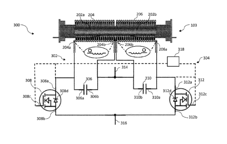
Referring now to Figure 3, there is illustrated an example of a circuit
comprised in the
controller 106. In this example, the circuit 300 is configured to control
current flow through
the first and second inductor coils 204,206 which are connected in the circuit
300 as shown in
CA 03041004 2019-04-17
WO 2018/073376 8 PCT/EP2017/076771
Figure 3. The circuit 300 is configured to control both the first and second
inductor coils
204,206 such that only one of the first and second inductor coils 204,206
operates to
significantly heat its respective susceptor region 202a, 202b at a given time.
In other words,
the topology of circuit 300 allows the same circuitry to be used to operate
two separate inductor
coils at different times to heat the susceptor 202.
It will be understood that when the first inductor coil 204 is being
controlled to generate
a varying magnetic field, a voltage will be induced in the second inductor
coil 206 and vice
versa. However in this example, the topology of the circuit 300 is such that
when one of the
inductor coils is controlled to generate a varying magnetic field, that is, to
heat the susceptor
202, an induced current sufficient to cause significant heating of the
susceptor 202 is prevented
from flowing in the other inductor coil. More specifically, when the first
inductor coil 204 is
being operated, current sufficient to cause significant heating of the
susceptor 202 is prevented
from flowing in the second inductor coil 206, and when the second inductor
coil 206 is being
operated, current sufficient to cause significant heating of the susceptor 202
is prevented from
flowing in the first inductor coil 204. In general, in examples of the
apparatus 100, the
controller 106 comprises circuitry arranged such that when one of the inductor
coils 204, 206
is being operated to heat the susceptor 202, a current sufficient to cause
significant heating of
the susceptor 202 is prevented from flowing in the other inductor coil 204,
206. Thus, when
one of the inductor coils is being operated to heat the susceptor 202, the
other inductor coil is
prevented from significantly heating the susceptor 202. As a result, since the
first and second
inductor coils 204 and 206 operate to substantially locally heat susceptor
regions 202a and
202b respectively, localised heating of the susceptor 202 can be achieved.
In the example of Figure 3, the circuit 300 includes first and second
resonator sections
302 and 304. The first inductor coil 204 is arranged to form part of the first
resonator section
302 of the circuit 300, and the second inductor coil 206 is arranged to form
part of the second
resonator section 304 of the circuit 300. The first resonator section 302 also
comprises a first
capacitor 306 comprising a first terminal 306a and a second terminal 306b, and
a first switch
308. Similarly, the second resonator section 304 further comprises a second
capacitor 310
comprising a first terminal 310a and a second terminal 310b, and a second
switch 312. The
first switch 308 is arranged to turn the first resonator section 302 on and
off, and the second
switch 312 is arranged to turn the second resonator section 304 on and off. In
some examples,
the components of circuit 300 may be arranged differently (in a different
topography) to as
shown in Figure 3. In some examples, additional or alternative components may
be included.
CA 03041004 2019-04-17
9
WO 2018/073376 PCT/EP2017/076771
In this example, the first and second switches 308 and 312 of the circuit 300
are field
effect transistors (FETs). More specifically, in this particular example, the
first and second
FETs 308 and 312 are N-channel FETs. As will be appreciated by those skilled
in the art, the
first FET 308 comprises a drain terminal 308a, a source terminal 308b and a
gate terminal 308c
and the second FET 312 comprises a drain terminal 312a, a source terminal 312b
and a gate
terminal 312c.
The first and second resonator sections 302 and 304, in this particular
example, are LC
(inductor/capacitor) resonator sections. In other words, each resonator
section 302, 304 is
equivalent to an LC resonator circuit.
A power supply connection 314 connects the second end 204b of the first coil
204, the
second terminal 306b of the first capacitor 306, the second end 206b of the
second coil 206 and
the second terminal 310b o f the second capacitor 310 to the positive terminal
o f the (DC) power
source 108 (not illustrated in Figure 3). The first end 204a of the first
inductor coil 204 and
the first terminal 306a of the first capacitor 306a are connected to the drain
terminal 308a of
the first FET 308 and, likewise, the first end 206a of the second inductor
coil 206 and the first
terminal 310a of the second capacitor 310 are connected to the drain terminal
312a of the
second FET 312. A negative terminal connection 316 connects the source
terminal 308b of the
first FET 308 and the source terminal 312b of the second FET 312 to the
negative terminal of
the power source 108.
As will be well understood by those skilled in the art, an N¨channel FET is in
an 'ON'
state when an appropriate control voltage is applied to its gate so that a
conductive path exists
between its drain and source. However, as will also be well understood by
those skilled in the
art, when an N¨channel FET is in an 'OFF' state (i.e. when the appropriate
control voltage is
not applied to its gate) it effectively acts as a diode. In Figure 3, the
diode functionality that
the first FET 308 exhibits when in its OFF state is represented by a first
diode 308d and the
diode functionality that the second FET 312 exhibits when in its OFF state is
represented by a
second diode 312d. The first diode 308d has its cathode connected to the first
end 204a of the
first inductor coil 204 and the first terminal 306a of the first capacitor
306, and its anode
connected to the negative terminal connection 316, and the second diode 312d
has its cathode
connected to the first end 206a of the second inductor coil 206 and the first
terminal 310a of
the first capacitor 310, and its anode connected to the negative terminal
connection 316.
CA 03041004 2019-04-17
WO 2018/073376 10 PCT/EP2017/076771
In this example, having regard to the first and second FETs 308 and 312, and
the
topology of the circuit 300, the phasing of the first and second inductor
coils 204 and 206 with
respect to each other is chosen such that when the first inductor coil 204 is
being operated,
current sufficient to cause significant heating of the susceptor 202 is
prevented from flowing
in the second inductor coil 206, and when the second inductor coil 206 is
being operated,
current sufficient to cause significant heating of the susceptor 202 is
prevented from flowing
in the first inductor coil 204.
In this example, one of the first 204 and second 206 inductor coils is
controlled to heat
the susceptor by having its corresponding first 308 or second 312 switch (as
the case may be)
being repeatedly turned on and off at a fast switching rate while the other
one of the first 204
and second 206 inductor coils remains inactive and its corresponding first 308
or second 312
switch (as the case may be) remains off More specifically, the first inductor
coil 204 is
controlled to heat the susceptor 202 when the first switch 308 is turned on
and off at a first
switching rate while the second switch 312 remains off, and the second
inductor coil 206 is
controlled to heat the susceptor 202 when the second switch 312 is turned on
and off at a second
switching rate while the first switch 308 remains off. A controller 318 is
provided in the circuit
300 to control the switching on and off of whichever of the first 308 and
second 312 FETs is
being operated. The first and second switching rates may be different or the
same.
The operation of the first 204 and second 206 inductor coils during this fast
switching
is explained in more detail below.
The functioning of the example circuit 300 will now be described in more
detail in the
context of the first inductor coil 204 being operated to heat the susceptor
202 when the first
FET 308 is being rapidly turned on and off by the controller 318.
When the first FET 308 is on, a DC current flows between the power supply
connection
314 and the negative terminal connection 316, and through the first inductor
coil 204. This DC
current is driven by the power supply 108. It will be understood that when a
current flows
through the first inductor coil 204, the first inductor coil 204 generates a
magnetic field as a
result of the current. The first inductor coil 204 stores energy in the
magnetic field it generates.
When the first FET 308 is on, the voltage across the first FET 308 is zero.
The first capacitor
306 is short circuited by the first FET 308 being on. In other words, when the
first FET 308 is
on, current between the power supply connection 314 and the negative terminal
connection 316
flows through the first FET 308.
CA 03041004 2019-04-17
WO 2018/073376 11 PCT/EP2017/076771
After the first inductor 204 has been allowed to generate a magnetic field due
to the
first FET 308 being on for a given amount of time and the first FET 308 is
subsequently turned
off, the current driven by the power supply 108 through the first inductor
coil 204 begins to
drop off. The first inductor coil 204 resists this change in current and
generates an induced
voltage using the energy that was stored in the magnetic field generated by
the first inductor
coil 204 when the first FET 308 was on and a direct current was flowing
through the first
inductor coil 204. Accordingly, when the first FET 308 is turned off after
being on, the first
capacitor 306 and the first inductor coil 204 resonate with each other.
Figure 4 shows the voltage across the first FET 308, as indicated by a voltage
trace 400,
when the first FET 308 is turned off and on twice during a time period that
the first inductor
204 is being operated to heat the susceptor 202.
The voltage trace 400 comprises a first section 400a when the first FET 308 is
on, a
second section 400b to 400d when the first FET 308 is switched off, a third
section 400f when
the first FET 308 is switched on again, a fourth section 400g when the first
FET 308 is switched
off again and a fifth section 400h when the first FET 308 is subsequently
switched on again.
The voltage across the first FET 308 is zero when the first FET 308 is on in
sections
400a, 400f and 400h.
When the first FET 308 is turned off as indicated by section 400b to 400d and
also by
section 400g, the first inductor coil 204 uses the energy stored in its
magnetic field (which
magnetic field was the result of a current flow when the first FET 308 was on)
to induce a
voltage that resists a drop in the current flowing through the first inductor
coil 204 as a result
of the first FET 308 being off. The voltage induced in the first inductor coil
204 causes a
corresponding variation in voltage across the first FET 308. During this
variation in voltage,
the first inductor coil 204 and the first capacitor 306 resonate with each
other. The voltage 400
initially increases (see for example 400b) as the induced voltage in the first
inductor coil 204
increases to oppose a drop in current due to the first FET 308 being off,
reaches a peak (see for
example 400c) and then, as the energy stored in the magnetic field of the
first inductor coil 204
diminishes, decreases back to zero (see for example 400d).
The varying voltage 400b to 400d and 400g produces a corresponding varying
current
and, since during the off time of the first FET 308, the first capacitor 306
and the first inductor
204 act as a resonant LC circuit, the total impedance of the first resonant
section 302 is at a
CA 03041004 2019-04-17
WO 2018/073376 12 PCT/EP2017/076771
minimum during this time. It will therefore be understood that the maximum
magnitude of the
varying current flowing through the first resonant section 302 will be
relatively large.
This relatively large varying current accordingly causes a relatively large
varying
magnetic field in the first inductor 204 which causes the susceptor 202 to
generate heat. The
time period over which the voltage across the first FET 308 varies as
indicated by section 400b
to d and by section 400g in this example depends on the resonant frequency of
the first resonant
section 302. As will be appreciated by those skilled in the art, the resonant
frequency of the
first resonant section 302 depends on the inductance of the first inductor
coil 204 and the
capacitance of the first capacitor 306.
Referring again to Figure 4, when the first FET 308 is off and the voltage
across the
first FET 308 subsequently decreases back towards OV (e.g. the voltage is
substantially at level
402 at point 400e), the controller 318 turns the first FET 308 back on so that
a dc current driven
by the power supply 108 flows again through the first inductor coil 204, and
the first inductor
coil 204 can store energy in the form of a magnetic field for the next time
the first FET 308 is
switched off to turn the resonant section 302 on as indicated by section 400g.
The time for which the controller 318 keeps the first FET 308 on (e.g. part
400f) may
be selected in accordance with the amount of energy that is desired to be
stored in the first
inductor coil 204, a part of which energy will be used to heat the susceptor
202 during the next
off time of the first FET 308 as indicated by 400g (on time of the resonant
part 202). The
amount of energy that may be stored in the first inductor coil 204 for a given
on time 400f of
the first FET 308 will depend on such factors as the voltage provided by the
power supply 108
and the number of turns on the first inductor coil 204, for example. It will
be understood that
in this example, when the voltage across the first FET 308 reaches OV, the
voltage at the drain
308a of the first FET 308 also reaches OV.
As the controller 318 repeatedly switches first FET 308 on and off in this way
at a
switching rate, the above described process is continuously repeated to heat
the susceptor 202.
Although the above description of the functioning of the circuit 300 is
presented in the
context of the first inductor coil 204 being operated to heat the susceptor
202, it will be
understood that the second inductor coil 206 forming part of the second
resonator section 304
will be operated in substantially the same way, with the second FET 312
performing functions
equivalent to the first FET 308 and the second capacitor 310 performing
functions equivalent
to the first capacitor 306.
CA 03041004 2019-04-17
WO 2018/073376 13 PCT/EP2017/076771
As previously mentioned above, the circuit 300 allows the first and second
inductor
coils 204,206 to be operated such that only one of the first and second coils
204 and 206
operates to significantly heat the susceptor 202 at a given time. This is
achieved firstly by
switching, at a given switching rate, one of the first or second FETs 308 or
312 while the other
FET remains off.
Secondly, when one of the first 204 and second 206 inductor coils is being
operated to
heat the susceptor 202 (as is described above with respect to the first coil
204), the circuit 300
is specifically configured so that a voltage that is induced in the other non-
operating coil by the
varying magnetic field of the operating coil does not cause a significant
current to flow through
the non-operating coil which itself would cause a varying magnetic field which
could heat the
susceptor. More specifically, when the first inductor coil 204 is being
operated to heat the
susceptor 202, a current sufficient to cause significant heating of the
susceptor 202 is prevented
from flowing through the second inductor coil 206, and when the second
inductor coil 206 is
being operated to heat the susceptor 202, a current sufficient to cause
significant heating of the
susceptor 202 is prevented from flowing through the first inductor coil 204.
This is necessary because, as mentioned above, the first 308 and second 312
FETs
effectively act as diodes when switched off and so may conduct a current if
they are forward
biased (i.e. the FETs are not perfect switches). Accordingly, it is important
that the circuit 300
is configured so that when one of the first 204 and 206 inductor coils is
being operated to heat
the susceptor 202, the voltage induced across the other non-operative inductor
coil does not
forward bias the intrinsic diode of the FET associated with that non-operative
inductor coil but
instead reverse biases it.
It will be understood by those skilled in the art that when considering two
inductors
which are magnetically coupled, their winding relative to each other
determines in which
direction the varying magnetic field generated by one inductor drives a
current/induces a
voltage in the other inductor.
The direction in which current is driven/voltage is induced in a coil can be
determined
by applying the well-known "right hand rule" relating direction of current to
the direction of a
magnetic field. The relative winding of the first and second inductor coils
204 and 206 may
be referred to as the phasing of the first and second inductor coils 204 and
206.
In the topology of the circuit 300 in Figure 3 the first inductor coil 204 and
the second
inductor coil 206 are wound in opposite senses as indicated by the dots which
appears at the
CA 03041004 2019-04-17
WO 2018/073376 14 PCT/EP2017/076771
first end 204a of the first inductor coil 204 and at the first end 206a of the
second coil 206. An
example of the heating arrangement 103 is also shown connected to the circuit
300 to illustrate
that the first and second inductor coils 204,206 are physically wound in
opposite directions in
this example.
Accordingly, when, for example, the controller 318 is repeatedly switching on
and off
the first FET 308 (as described above) in order to cause the first inductor
coil 204 to heat the
susceptor 202, each time the first FET 308 is switched off, a positive voltage
is generated at
the first end 204a of the first inductor coil 204 and a corresponding smaller
positive voltage is
induced at the first end 206a of the second inductor coil 206 due to magnetic
coupling. This
results in the intrinsic diode of the second FET 312 being reverse biased and
hence current is
substantially prevented from flowing through the second FET 312. Although some
current
may flow between the second inductor coil 206 and second capacitor 310, a
current sufficient
to generate a varying magnetic field strong enough to significantly heat the
susceptor 202 is
prevented from flowing through the second inductor coil 206 due to the second
FET 312 being
reverse biased. Also, as a result of the second FET 312 being reverse biased
and a current
being prevented from flowing through it when the first FET 308 is repeatedly
being switched
on and off and the second FET 312 remains off, a significant amount of energy
is prevented
from building up in the second inductor coil 206 so that a significant amount
of energy is not
drawn away from the first inductor coil 204 being operated to heat the
susceptor 202.
Similarly, when, for example, the controller 318 is repeatedly switching on
and off the
second FET 312 in order to cause the second inductor coil 206 to heat the
susceptor 202, each
time the second FET 312 is switched off, a positive voltage is generated at
the first end 206a
of the second inductor coil 206 and a corresponding smaller positive voltage
is induced at the
first end 204a of the first inductor coil 204 due to magnetic coupling. This
results in the
intrinsic diode of the first FET 308 being reverse biased and hence current is
substantially
prevented from flowing in the first FET 308. Although some current may flow
between the
first inductor coil 204 and first capacitor 306, a current sufficient to
generate a varying magnetic
field strong enough to significantly heat the susceptor 202 is prevented from
flowing through
the first inductor coil 204 due to the first FET 308 being reverse biased.
Also, as a result of the
first FET 308 being reverse biased and a current being prevented from flowing
through it when
the second FET 312 is repeatedly being switched on and off and the first FET
308 remains off,
a significant amount of energy is prevented from building up in the first
inductor coil 204 50
CA 03041004 2019-04-17
WO 2018/073376 15 PCT/EP2017/076771
that a significant amount of energy is not drawn away from the second inductor
coil 206 being
operated to heat the susceptor 202..
Thus, preventing a current sufficient to significantly heat the susceptor from
flowing in
the non-operating inductor coil in this way provides the additional advantage
of preventing the
non-operating inductor coil from taking a significant amount of energy away
from the operating
coil in order to generate its own magnetic field, which energy is used to
generate a varying
current and therefore magnetic field by the operating coil in order to heat
the susceptor 202.
Referring now to Figure 5, there is illustrated a second circuit 500
configured to control
the first and second inductor coils 204 and 206 comprised in the controller
106.
Many of the components of the circuit 500 are identical to corresponding
components
in the circuit 300 and function in an identical way. These components have
been given the
same reference numerals as they have in Figure 3 and in the interests of
brevity will not be
described in detail again. In some examples, the components of circuit 500 may
be arranged
differently (in a different topography) to as shown in Figure 5. In some
examples, additional
or alternative components may be included.
In this example, the circuit 500 is used to control a heating arrangement in
which both
the first and second inductor coils 204,206 are wound in the same direction
relative to each
other (have the same phasing) as indicated by the dots which appears at the
first end 204a of
the first inductor coil 204 and at the second end 206b of the second coil 206.
An example of
the heating arrangement 103 is shown connected to the circuit 500 to
illustrate that the first and
second inductor coils 204,206 are physically wound in the same direction in
this example. One
difference in the circuit topology of the circuit 500 compared with the
circuit 300 is the
configuration of the wiring connecting the second inductor coil 206 to the
rest of the circuit.
As mentioned above, in circuit 300, the second end 206b of the second coil 206
connects to the
positive terminal of the power source 108 via the power supply connection 314,
and the first
end 206a of the second coil 206 connects to the drain terminal 312a of the
second FET 312. In
contrast, in circuit 500, the first end 206a of the second coil 206 connects
to the positive
terminal of the power source 108 via the power supply connection 314, and the
second end
206b of the second coil 206 connects to the drain terminal 312a of the second
FET 312.
Although, in this example, the inductor coils 204,206 are wound in the same
direction,
the topology of circuit 500 is such that when the first inductor coil 204 is
being operated, each
time the first FET 308 is switched off, the voltage induced across the second
inductor coil 206
CA 03041004 2019-04-17
WO 2018/073376 16 PCT/EP2017/076771
reverse biases the intrinsic diode 312d of the second FET 312, and that when
the second
inductor coil 206 is being operated, each time the second FET 312 is switched
off, the voltage
induced across the first inductor coil 204 reverse biases the intrinsic diode
308d of the first
FET 308. As in the case of the circuit 300, in the example of the controller
318 repeatedly
switching the first FET 308 on and off to cause the first inductor coil 204 to
heat the susceptor
202, each time the first FET 308 is switched off, a positive voltage is
generated at the first end
204a of the first inductor coil 204. However, in contrast to circuit 300, in
circuit 500 a
corresponding smaller positive voltage is induced at the second end 206b
(instead of the first
end 206a as is the case for circuit 300) of the second inductor coil 206 due
to magnetic coupling.
Since in circuit 500, the second end 206b of the second inductor coil 206
connects to the drain
terminal 312 of the second FET 312, each time the first FET 308 is switched
off, the second
FET 312 is reverse biased. Hence current is substantially prevented from
flowing through the
second FET 312. Conversely, when the controller 318 repeatedly switches the
second FET
312 on and off to cause the second inductor coil 206 to heat the susceptor
202, each time the
second FET 312 is switched off, the first FET 308 becomes reverse biased in a
similar manner,
and hence current is substantially prevented from flowing through the first
FET 308. Thus,
although in circuit 500 the inductor coils 204,206 are physically wound in the
same sense, the
circuit 500 provides the advantages mentioned above with respect to the
circuit 300 by having
the inductor coils 204,206 connected to the circuit in a way such that a
substantial current is
prevented from flowing in the inactive inductor coil.
However, the topology of the circuit 500 may require a more difficult printed
circuit
board layout with high current traces. In some examples, the simpler topology
of the circuit
300 may be preferred.
Referring now to Figure 6, an example controller 318a, 318b for controlling
the circuit
300 of Figure 3 will be described. In Figure 6, the circuit 300 of Figure 3 is
reproduced except
that the controller 318 is represented as two different sections, namely, a
zero voltage detector
section 318a and a switching section 318b, and that an example heater
arrangement 103 is not
shown connected to the circuit.
When one of the first 308 and second 312 FETs is being repeatedly switched on
and
off, as described above with respect to Figure 3, to operate a respective one
of the first 204 and
second 206 inductor coils, the zero voltage detector section 318a detects
when, after the
respective FET has been switched off, the voltage across that FET has returned
to zero (e.g.
CA 03041004 2019-04-17
WO 2018/073376 17 PCT/EP2017/076771
point 400e in Figure 4) or, is close to zero, and in response to the zero
voltage detector section
318a making this detection, the switching section 318b switches the respective
FET on again.
The switch controller section 318a is a zero voltage detection circuit
comprising first
600 and second 602 small signal diodes, a pull up resistor 604, and a logic
power source 606.
Taking the example of the second inductor coil 206 being operated to heat the
susceptor 202,
the functioning of the switch controller section 318a, will now be described.
When the second inductor coil 206 is being operated to heat the susceptor 202,
the first
FET 308 remains off When the first FET 308 remains off, the first small signal
diode 600 has
either no bias or is reverse biased depending on the voltages at the logic
power source 606 and
the power supply connection 314, that is, the voltage at the cathode end of
the first small signal
diode 600 is either substantially the same as or higher than the voltage at
the anode end of the
first small signal diode 600.
During the switching at the switching rate of the second FET 312, when the
second
FET 312 is off and the voltage across it varies as indicated by 4b-d of figure
4, the second small
signal diode 602 is reversed biased. At the end of this variation in voltage,
when the voltage
reaches OV as indicated by 400e, or is close to OV, the second small signal
diode 602 becomes
forward biased. The second switch controller section 318b, in this example,
includes one or
more flip-flop means (not shown) that can be set to switch the first and
second FETs 308 and
318 on or off. Accordingly, when the second small signal diode 602 is forward
biased at 400e,
the signal from the second small signal diode 602 is provided to a flip-flop
means (not shown)
included in the second switch controller section 318b in order to set it to
switch the second FET
312 on. When the second FET 312 is on, the second small signal diode 602 is
reverse biased.
As already described above with reference to the Figure 3 circuit, the second
FET 312
remains on until a required amount of energy is stored in the associated
inductor coil 206. In
this example, the magnitude of the current flowing in the second inductor coil
206 may be
measured by suitable current measuring means (not shown) that may be included
in the second
switch controller means 318b. Once the magnitude of the current in the second
inductor coil
206 is at a level corresponding to the desired amount of energy being stored
in the second
inductor 206, the flip-flop is reset in order to switch the second FET 312 off
and initiate another
variation of the voltage 400g across the first capacitor 310.
In one particular example, the logic power source 606 provides a voltage of
2.5V, and
the signal from the second small signal diode 602 is provided to the flip-flop
means mentioned
CA 03041004 2019-04-17
WO 2018/073376 18 PCT/EP2017/076771
above included in the second switch controller section 318b. The flip-flop
means switches at
half of the voltage of the logic power source 606, that is, at 1.25V in this
example. This means
that the forward bias voltage of the second small signal diode 602 and the
voltage at the second
FET 312 drain must sum to 1.25V in order that the digital logic circuit turns
the second FET
312 on. In this example therefore, the second FET 312 is switched on when its
drain 312a is
at 0.55V rather than at OV as referenced above. It should be noted that
ideally, switching should
occur at OV across the FET 312 for maximum efficiency. This zero voltage
switching
advantageously prevents the second FET 312 from discharging the second
capacitor and
thereby wasting energy stored in the second capacitor 310.
However, the loss in efficiency due to the use of this digital logic circuit
as opposed to,
for example, an analogue comparator circuit can be thought to be offset by the
advantageous
saving in circuit parts and cost. In this example 0.55V is an acceptable
voltage across the
second FET 312 at which to switch the second FET 312 back on.
It should be noted that in this example, the zero voltage switching as
described above
occurs in steady state conditions, that is, when the repeated switching of the
second FET 312
is ongoing. In order to commence operation of the second inductor coil 206 by
commencing
the repeated switching of the second FET 312, an additional signal may be
provided to the
second FET 312.
Although in the above description the functioning of the zero voltage
detection circuit
318a is described in relation to controlling switching of the second FET 312,
it will be
understood that the zero voltage detection circuit 318a functions in the same
way, using the
first small signal diode 600 instead of the second small signal diode 602, to
control the first
FET 308.
It will be appreciated that the first and second inductor coils 204,206, in
some examples,
may have at least one characteristic different from each other. For example,
the first inductor
204 may have at least one characteristic different from the second inductor
coil 206. More
specifically, in one example, the first inductor coil 204 may have a different
value of inductance
than the second inductor coil 206. In another example, the first and second
inductor coils be
different lengths such that the first inductor coil 204 is wound over a larger
section of the
susceptor 202 or vice versa. In another example, the first inductor coil 204
may comprise a
different number of turns than the second inductor coil 206. In yet another
example, the first
inductor coil 204 may be composed of a different material to the second
inductor coil 206. It
CA 03041004 2019-04-17
WO 2018/073376 19 PCT/EP2017/076771
is envisaged that the first inductor coil 204 may have one or more different
characteristics to
the second inductor coil 206 based on, for example, how the smokable material
within the
volume of the susceptor is desired to be heated. In some examples, the first
and second inductor
coils 204 and 206 may be substantially identical.
The above examples have been described with the circuits 300 and 500
comprising N-
channel FETs. However, in some examples, circuits comprising P-channel FETs
may be used
instead. For example, P-channel FETs may be used in circuit 300 if the
connection 314 shown
in Figure 3 is instead connected to the negative terminal of the power source
108, and the
connection 316 is instead connected to the positive terminal of the power
source 108.
The various embodiments described herein are presented only to assist in
understanding
and teaching the claimed features. These embodiments are provided as a
representative sample
of embodiments only, and are not exhaustive and/or exclusive. It is to be
understood that
advantages, embodiments, examples, functions, features, structures, and/or
other aspects
described herein are not to be considered limitations on the scope of the
invention as defined
by the claims or limitations on equivalents to the claims, and that other
embodiments may be
utilised and modifications may be made without departing from the scope of the
claimed
invention. Various embodiments of the invention may suitably comprise, consist
of, or consist
essentially of, appropriate combinations of the disclosed elements,
components, features, parts,
steps, means, etc., other than those specifically described herein. In
addition, this disclosure
may include other inventions not presently claimed, but which may be claimed
in future.