Note: Descriptions are shown in the official language in which they were submitted.
CA 03041075 2019-04-17
WO 2018/083107
PCT/EP2017/077943
- 1 -
METHODANDAPPARATUS FOR MEASURINGA CONCENTRATION OFA GAS
The invention addressed herein relates to a method for
measuring a concentration of a gas in a container having a
wall with at least one deformable portion. Under further
aspects, the invention relates to a method of producing a
sealed container containing a filling gas volume having a
concentration of a monitored gas lying in a predetermined
concentration range and to an apparatus for performing the
methods.
In several applications there are specific requirements to
the composition of a gas present in a container for
packaging sensitive contents, such as medicals or food.
E.g. for process control or quality control there is a need
to determine a concentration of a gas in a container before
packaging, during packaging or after packaging. The
relevant gas concentration may e.g. be the concentration of
oxygen in case the content of the container may be oxidized
and thereby undergo a degradation. Low oxygen concentration
may suppress bacterial or fungal activity, as well.
As an example, infrared absorption spectroscopy is a known
method, which is suitable to determine the concentration of
specific monitored gases in a container and which allows
determining a concentration of a gas in a non-invasive way,
i.e. without the need of entering with a part of the
measuring apparatus into the container. It is only infrared
CA 03041075 2019-134-17
WO 2018/083107
PCT/EP2017/077943
- 2 -
radiation that passes through the walls of the container
and through the gas to be analyzed. The radiation intensity
of the infrared radiation is reduced in absorption bands
specific for different species of gas.
It is not uncommon to use containers having flexible or
deformable walls for packaging sensitive products such as
pharmaceuticals or food. Such containers may be bags, trays
with a covering foil or containers being semi-rigid, e.g.
containers having walls comprising plastic or cardboard. As
the resulting absorption depends on the gas concentration
and on the travelling distance of the radiation in the gas,
the precise measurement of gas concentration in containers
having deformable walls is difficult. Such containers may
have a large variability between individual containers. In
particular, if the process of filling content into such a
container with deformable walls is not yet finished, the
contents volume and with it several dimensions of the
container may change from measurement to measurement or
even during a single measurement, thus influencing the
travelling distance of the radiation in the gas and
therewith the absorbed amount of radiation.
The object of the present invention is to provide a method
for measuring a concentration of a gas in a container
having a wall with at least one deformable portion that
eliminates some difficulties of the known methods.
This object is achieved by a method according to claim 1.
CA 03041075 2019-134-17
WO 2018/083107
PCT/EP2017/077943
- 3 -
The method according to the invention is a method for
measuring a concentration of a gas in a container having a
wall with at least one deformable portion, the monitored
gas absorbing electromagnetic radiation at least in a
specific spectral range. The method comprises the steps of:
- biasing the deformable portion and a further portion of
the wall opposite said deformable portion between opposite
positioning surfaces, thereby forming a biased volume of
the container between said opposite positioning surfaces,
- during a measuring time, transmitting electromagnetic
radiation into the biased volume and receiving transmitted
or reflected radiation of the transmitted radiation from
the biased volume along respective radiation paths,
- relatively moving, during the measuring time, at least
one of the deformable portion and of the further portion ,
and at least one of the radiation paths, and
- determining the concentration of the gas from the
radiation received
The inventor has recognized that with this method gas
concentrations of the gas can be measured with high
precision. In particular, low concentrations of the
monitored gas, leading only to weak absorption of the
intensity can be determined with small error. By the
relative movement of at least one of the deformable portion
of the wall of the container or the further portion of the
wall of the container relative to at least one of the
radiation paths, disturbing effects that have their origin
CA 03041075 2019-134-17
WO 2018/083107
PCT/EP2017/077943
- 4 -
in reflections and scattering on material of portions of
the wall that is traversed by the electromagnetic
radiation, are averaged out. Successive measurements on the
same container are more reproducible. Small variation in
the exact form or surface structure of different containers
of the same type have less influence on the gas
concentration determined. The inventor has recognized that
interference effects between various possible radiation
paths may erroneously interpreted as absorption in a gas.
This type of error becomes relevant when measuring low
concentrations of a gas or when measuring with short
radiation path length inside the gas. Interference effects
may become severe when highly coherent electromagnetic
radiation is applied, such as laser light. The method
according to the invention effectively reduces this type of
error.
With the step of biasing the deformable portion and a
further portion of the wall opposite the deformable portion
between opposite positioning surfaces, the contact to the
positioning surfaces is established at two portions of the
wall that lie opposite to each other with respect to the
content volume of the container. With this, the length of
the radiation path inside the content volume can be
properly defined even for a container having highly
flexible walls, as e.g. a bag for storing a liquid.
The step of biasing the deformable portion and a further
portion of the wall opposite the deformable portion between
opposite positioning surfaces may be performed in various
CA 03041075 2019-134-17
WO 2018/083107
PCT/EP2017/077943
- 5 -
ways. E.g. filling liquid into the container is a possible
way to achieve the biasing.
It is of course assumed that the walls the container is at
least partially transparent or translucent for the
electromagnetic radiation in the specific spectral range
used in the method.
In one embodiment of the method according to the invention,
which may be combined with any of the embodiments still to
be addressed unless in contradiction, the relatively moving
is performed in a cyclic movement having a repetition time
corresponding to the measuring time or to a fraction of the
measuring time.
In a cyclic movement the positions of the moving objects
are the same again after a repetition time or integer
multiples of the repetition time. With this embodiment, all
positions of the section of the wall in movement that are
reached during a cycle of the movement contribute to the
measurement. Effective averaging out of effects depending
on the exact position of sections of the wall is achieved
by this embodiment.
In one embodiment of the method according to the invention,
which may be combined with any of the preaddressed
embodiments and any of the embodiments still to be
addressed unless in contradiction, the relatively moving is
induced by acting on the wall of the container by means of
a manipulating element.
CA 03041075 2019-134-17
WO 2018/083107
PCT/EP2017/077943
- 6 -
The manipulating element may e.g. be used to push against
the wall of the container or to pull some part of the wall
of the container to induce a movement of at least one of
the deformable portion or the further portion of the wall.
The manipulating element may be a manipulating element used
for handling the container in an automated way, e.g. for
transporting the container between different stations of an
automated filling system. The manipulating element may be
configured to manipulate at least a part the wall of a
container, once the container is inserted between the
opposite positioning surfaces.
In one embodiment of the method according to the invention,
which may be combined with any of the preaddressed
embodiments and any of the embodiments still to be
addressed unless in contradiction, the relatively moving is
induced by moving a first positioning surface of the
opposite positioning surfaces with respect to a second
positioning surface of the opposite positioning surfaces,
thereby holding the length of the radiation path
substantially constant.
In this embodiment, the movement of the first positioning
surface is effectively transmitted to a movement of at
least one of the opposing portions of the wall. As the two
positioning surfaces are moved relative to each other,
different portions of the wall of the container may
rearrange themselves in various positions relative to each
other during the movement, leading to various
configurations regarding to possible scattering ways of the
CA 03041075 2019-134-17
WO 2018/083107
PCT/EP2017/077943
- 7 -
radiation path across the container. The length of the
radiation path is held substantially constant, thus only
the unwanted effects are varied while holding the decisive
path length of the radiation path constant. Possible
movements holding the length of the radiation path
substantially constant are for example a translation
perpendicular to the radiation path, a rotation around an
axis along the radiation path, or a tilting around a point
defining the radiation path, such as a point on a
reflector. Alternatively, microscopic translations parallel
to the radiation hold the decisive path length of the
radiation path substantially constant as well.
The relative movement of the positioning surfaces may be
continuous or step-wise, e.g. with a time span without
movement in each step.
In one embodiment of the method according to the invention,
which may be combined with any of the preaddressed
embodiments and any of the embodiments still to be
addressed unless in contradiction, the step of determining
the concentration is based on radiation received at points
in time corresponding to different positions of at least
one of the deformable portion and the further portion of
the wall reached during the movement.
According to this embodiment, signal received, e.g.
received by a detector in operative connection with an
analog to digital converter, may be accumulated over time
and the accumulated signal may be evaluated at the end of
the measurement time. An alternative possibility is
CA 03041075 2019-134-17
WO 2018/083107
PCT/EP2017/077943
- 8 -
evaluating a series of measurements to produce a series of
corresponding preliminary concentrations and calculating
e.g. a mean value from the series of preliminary
concentrations. The way of processing the signal according
to this embodiment may be seen as a low pass filtering of
signals received at the detector, whereby the signals
having a frequency corresponding to the relatively moving
is filtered out.
Depending on the embodiment in discussion, the position of
at least one of the portions of the wall may be dependent
on the position of the manipulating element or the position
of the opposite positioning surfaces.
In one embodiment of the method according to the invention,
which may be combined with any of the preaddressed
embodiments and any of the embodiments still to be
addressed unless in contradiction, the transmitting is
performed by an electromagnetic radiation source, in
particular a laser, having a spectral bandwidth narrower
than the specific spectral range and with a tunable
transmitter frequency and wherein the transmitter frequency
is periodically swept over the specific spectral range.
A narrow band radiation source that may be applied in this
embodiment of the method may e.g. be tunable diode laser.
The sweeping of the frequency may in this case be performed
by varying the driving current of the diode laser.
Wavelength modulation techniques can be applied this way.
The periodical sweeping may be performed with a repetition
rate in the Hertz range. Superimposed to the periodical
CA 03041075 2019-134-17
WO 2018/083107
PCT/EP2017/077943
- 9 -
sweeping, a modulation of higher frequency, e.g. in the
kilo Hertz range, may be applied. In the second case,
signals having the modulation frequency and/or higher order
sidebands of the modulation frequency may be accurately
detected in the received signal, e.g. by means of a lock-in
amplifier. By means of such wavelength modulation method,
signals in the specific spectral range received, but
stemming from disturbing sources, may be filtered out based
on their frequency characteristic. Analysis of e.g. the
intensity ratio between first order and second order
sidebands may provide a possible way of measuring
absorption related to a gas without knowing the absolute
fraction of the radiation arriving at the detector.
In one embodiment of the method according to the invention,
which may be combined with any of the preaddressed
embodiments and any of the embodiments still to be
addressed unless in contradiction, the step of biasing is
performed by filling the container at least partially with
a filling gas and thereby increasing a diameter of the
container until the diameter extends between the opposite
positioning surfaces.
This embodiments combines in an efficient way the filling
of the container by a filling gas with the subsequent
measurement of the concentration of a monitored gas. The
concentration of the monitored gas species or unwanted gas
species in the filled container may be higher than the
concentration of this gas species present in the filling
gas before its introduction into the container, as there
CA 03041075 2019-134-17
WO 2018/083107
PCT/EP2017/077943
- 10 -
may be residuals of the monitored gas in the container,
adhere to the wall of the container or outgas from a liquid
or solid content of the container.
In one embodiment of the method according to the invention,
which may be combined with any of the preaddressed
embodiments and any of the embodiments still to be
addressed unless in contradiction, the step of biasing is
performed by moving at least one of the opposing
positioning surfaces towards at least one of the deformable
portion and further portion of the wall.
This embodiment may e.g. used for measurement of a gas
concentration in an already filled and sealed container,
e.g. in the context of quality control.
Further in the scope of the invention lies a method of
producing a sealed container containing a filling gas
volume having a concentration of a monitored gas, in
particular oxygen, lying in a predetermined concentration
range, in particular a concentration below 100 ppm, in
particular below 10 ppm, further in particular below 1 ppm,
the method comprising:
a) providing a filling gas having a concentration of the
monitored gas lying in the predetermined concentration
range,
b) at least once filling a container with the provided
filling gas,
CA 03041075 2019-134-17
WO 2018/083107
PCT/EP2017/077943
- 11 -
c) applying the steps of the method according to the
invention or any one of its embodiments to determine a
concentration of the monitored gas,
if the concentration lies outside the predetermined
concentration range:
d) extracting at least a part of the provided filling gas
from the container and repeating steps b) and c), or
if the concentration lies in the predetermined
concentration range:
e) sealing the container.
With this method, the packaging process and a quality
control step are efficiently integrated. Sealed containers
with a specified gas concentration may be prepared with
this method as a preparation step for a packaging process.
Container with sensitive contents may be produced by this
method in a way assuring long shelf lives and integrity of
the contents of the container.
Further in the scope of the invention lies a method of
producing a sealed container containing a liquid or solid
content and a filling gas volume having a concentration of
a monitored gas, in particular oxygen, lying in a
predetermined concentration range, in particular a
concentration below 100 ppm, in particular below 10 ppm,
further in particular below 1 ppm, the method comprising
filling the liquid or solid content into the container
followed by the method of producing a sealed container
CA 03041075 2019-134-17
WO 2018/083107
PCT/EP2017/077943
- 12 -
containing a filling gas volume having a concentration of a
monitored gas as disclosed above.
The invention is further directed to an apparatus for
performing the methods according to the invention or its
embodiments. Such an apparatus comprises:
- a first positioning surface and a second positioning
surface of at least a first positioning element, the first
and second positioning surfaces defining a space in between
them;
- a transmitter for electromagnetic radiation in the
specific spectral range and a detector for electromagnetic
radiation in the specific spectral range, the transmitter
and the detector being arranged to define a radiation path
traversing the space on the way from the transmitter to the
detector;
- an actuator element being mechanically coupled to a
manipulating element configured to manipulate at least a
part the wall of a container, once a container is inserted
between the first and second positioning surfaces, thereby
moving a section of the wall of the container relatively to
at least one of the radiation paths and across at least one
of the radiation paths, the section being adjacent to at
least one of the first and second positioning surfaces;
- a control unit operably connected to the transmitter, to
the detector and to the actuator element;
CA 03041075 2019-134-17
WO 2018/083107
PCT/EP2017/077943
- 13 -
- an evaluation unit operably connected to the detector and
configured to determine a gas concentration based on the
electromagnetic radiation received by the detector.
The transmitter of electromagnetic radiation may be a
laser, in particular a tunable diode laser. The detector
may be a photodiode, in a particular a silicon photodiode.
The electromagnetic radiation may be radiation in the near-
infrared-range, in particular in a range around an
absorption line of the monitored gas. In the case of oxygen
being the monitored gas, the specific spectral range may be
a range covering a few nanometers wavelength around 760
nanometer wavelength. Other spectral ranges, such as
spectral ranges comprising absorption bands of water vapor,
carbon dioxide, carbon monoxide, etc. may be selected.
Transmitter and/or detector may be connected to a
transmitter head and a receiver head, respectively, by
optical fibers. In this case, the optical fibers are part
of the radiation path between the transmitter and the
detector. The optical fibers do not contribute to the
narrow band absorption of radiation typical for absorption
of a gas.
Transmitter and detector, or transmitter head and receiver
head, respectively, may be arranged on opposite positioning
surfaces. Transmitter and detector, or transmitter head and
receiver head, respectively, may be arranged on the same of
the positioning surfaces and a reflector, such as a mirror,
may be placed on the other of the positioning surfaces. By
using a reflector being semi-reflective to the
electromagnetic radiation in the specific spectral range on
CA 03041075 2019-134-17
WO 2018/083107
PCT/EP2017/077943
- 14 -
the side of the transmitter and the detector, or
transmitter head and receiver head, respectively, and a
fully reflective reflector on the opposite side,
configuration with a radiation path leading several times,
e.g. four or six times, along the diameter of the container
are possible. Additional positioning surfaces, such as a
third and a fourth positioning surface may be implemented.
Additional positioning surfaces may be useful in defining a
more complex radiation path, e.g. a radiation path crossing
the container several times.
The space defined in between the positioning surfaces may
be adapted to receive the deformable portion of the wall in
between them. The deformable portion of the wall may
delimit a variable content volume of the container. The
manipulating element may be a manipulating element used for
gripping the container or for handling the container in an
automated way, e.g. for transporting the container between
different stations of an automated filling system.
The manipulating element is configured to manipulate at
least a part of the wall of the container in such a way
that a section of the wall of the container is moved
relatively to at least one of the radiation paths. The part
of the wall, which is manipulated, may be distant from the
section of the wall, which undergoes a movement relative to
a radiation path. The movement of the section of the wall
occurs across at least one of said radiation paths. The
section of the wall is adjacent to at least one of the
first and second positioning surfaces. The section of the
wall may as well be adjacent to additional positioning
CA 03041075 2019-134-17
WO 2018/083107
PCT/EP2017/077943
- 15 -
surfaces, if there are any. The manipulating element may
for example be configured to move a part of the wall of the
container together with the transmitter for electromagnetic
radiation, such that the radiation path emitted from the
transmitter scans across the section of the wall laying
opposite to the part of the wall of the container being
moved. The manipulating element may, as another example, be
configured to pull on a part of the wall directly
neighboring the section of the wall undergoing a relative
movement in relation to at least one of the radiation
paths.
In one embodiment of the apparatus according to the
invention, which may be combined with any of the
preaddressed embodiments and any of the embodiments still
to be addressed unless in contradiction, the first
positioning surface is arranged on the manipulating
element, the manipulating element being movable with
respect to the second positioning surface, in particular
being translatable and/or rotatable and/or pivotable with
respect to the second positioning surface.
This embodiment enables an effective way of inducing the
relatively moving of a portion of the wall and a radiation
path.
In one embodiment of the apparatus according to the
invention, which may be combined with any of the
preaddressed embodiments and any of the embodiments still
to be addressed unless in contradiction, the first and
CA 03041075 2019-134-17
WO 2018/083107
PCT/EP2017/077943
- 16 -
second positioning faces are flat and are arranged
substantially parallel to each other.
In one embodiment of the apparatus according to the
invention, which may be combined with any of the
preaddressed embodiments and any of the embodiments still
to be addressed unless in contradiction, the first
positioning element is translatable parallel to the second
positioning face.
This embodiment enables e.g. inducing a large movement of a
portion of the wall perpendicular to the radiation path
while keeping the length of the radiation path inside the
container substantially constant.
In one embodiment of the apparatus according to the
invention, which may be combined with any of the
preaddressed embodiments and any of the embodiments still
to be addressed unless in contradiction, at least one of
the first and second positioning faces is rigidly connected
to a reflector for the electromagnetic radiation.
The radiation path may be independent of the exact position
of the reflector as the position of reflection point is not
moved when moving the reflector in a direction
perpendicular to an optical axis. A radiation path crossing
at least twice the interior volume of the container is
possible according to this embodiment.
CA 03041075 2019-134-17
WO 2018/083107
PCT/EP2017/077943
- 17 -
In one embodiment of the apparatus according to the
invention, which may be combined with any of the
preaddressed embodiments and any of the embodiments still
to be addressed unless in contradiction, the apparatus
further comprises a gas-flow introducing device adapted to
be connected to an opening of the container and being
operable to inflate and deflate the container.
With this embodiment, filling the container with gas or
flushing the container with gas are possible in the
apparatus that performs the measurement of the
concentration of a gas. Inflating the container may be
applied in the biasing step of the method according to the
invention.
The invention is further directed to a filling facility for
filling containers, the containers having a wall delimiting
an inner volume of the containers, the wall having at least
one deformable portion, wherein the filling facility
comprises an apparatus according to the invention or any of
the embodiments of the apparatus.
The apparatus may be applied to perform a quality control
or a process control step in an automatized filling
facility configured to handle containers having walls with
at least a deformable portion. The filling facility
according to the invention leads to precise determination
of gas concentration in containers, such as in flexible
bags, for which determination of gas concentration is
generally difficult.
CA 03041075 2019-134-17
WO 2018/083107
PCT/EP2017/077943
- 18 -
The invention shall now be further exemplified with the
help of figures. The figures show:
Fig. 1 a flow chart of the method according to the
invention;
Fig. 2 a schematic view of the situation occurring
during the measuring time in the method according to
the invention;
Fig. 3 a schematic view of an embodiment of an
apparatus according to the invention;
Fig. 4.a) to 4.c) schematic views of different
arrangements defining a radiation path;
Fig. 5 a schematic view of a further embodiment of an
apparatus according to the invention;
Fig. 6.a) to 6.c) schematic views of the situation
occurring in steps of an embodiment of the method
according to the invention;
Fig. 7 a flow chart of the method of producing a
sealed container containing a filling gas volume
having a concentration of a monitored gas in a
predetermined concentration range.
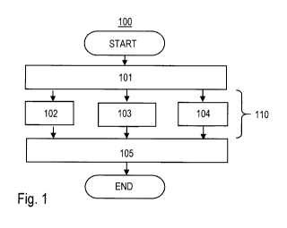
Fig. 1 shows, schematically and simplified, a flow chart of
the method 100 according to the invention. The method 100
is a method for measuring a concentration of a gas in a
container having a wall with at least one deformable
portion. The gas absorbs electromagnetic radiation at least
in a specific spectral range. First, the step of biasing
CA 03041075 2019-134-17
WO 2018/083107
PCT/EP2017/077943
- 19 -
101 the deformable portion and a further portion of the
wall opposite the deformable portion between opposite
positioning surfaces is performed. Thereby a biased volume
of the container between the opposite positioning surfaces
is formed. During a measuring time 110, three processes are
performed simultaneously. These processes are:
- transmitting 102 electromagnetic radiation into the
biased volume,
- receiving 103 transmitted or reflected radiation of the
transmitted radiation from the biased volume along
respective radiation paths, and
- relatively moving 104 at least one of the deformable
portion and of the further portion and at least one of the
radiation paths.
The final step is the determination 105 of the
concentration of the gas from the radiation received.
Fig. 2 shows, schematically and simplified, a view of the
situation occurring during the measuring time in the method
according to the invention. A radiation path 6 starts at a
transmitter 4 for electromagnetic radiation and ends at a
detector 5 for electromagnetic radiation. A first 1 and a
second 2 opposite positioning faces define a volume for
receiving at least a part of the container. Cross sections
through elements that define the positioning faces are
indicated by diagonal hatching, cross sections through the
positioning faces are visible as lines in this figure. The
positioning faces are arranged opposite to each other. A
CA 03041075 2019-134-17
WO 2018/083107
PCT/EP2017/077943
- 20 -
container 20 is placed between the first 1 and the second 2
positioning face. As result of previous steps of the
method, the first section 21 of a wall of the container is
in contact with the first positioning face. On the opposite
side of the contents volume of the container 20, a second
section 22 of a wall of the container is in contact with
the second positioning face 2. This way, a section of the
radiation path inside the container is properly defined. A
manipulating element 16 is moved by means of an actuator
element 12 against the wall of the container, as indicated
by the double-arrow 17. This movement induces a movement -
indicated by double-arrow 24 - of a section of the wall of
the container with respect to the radiation path.
Fig. 3 shows a schematic and partially cross-sectional view
of an embodiment of an apparatus according to the
invention. In this embodiment, the first positioning
surface 1 is a surface of a manipulating element 16 and is
movable parallel to the second positioning surface 2, which
is a surface of a first positioning element 1. A
transmitter 4 and a detector 5 are arranged in fixed
position with respect to the first positioning element 1'.
The radiation path 6 is established from the transmitter 4
via a reflector 11 to the detector, thereby twice crossing
the volume inside the container 20. The reflector 11 is
movable together with the second positioning face 2. The
movement of the reflector does not significantly change the
length of the radiation path, as the movement occurs nearly
perpendicular to the radiation path and the position of the
CA 03041075 2019-134-17
WO 2018/083107
PCT/EP2017/077943
- 21 -
reflection point on the reflector is not affected by the
movement. An actuator element 12 is mechanically coupled to
the manipulating element 16. The manipulating element is
translatable in the direction indicated by double-arrow 17.
A control unit 8 is operatively connected to the
transmitter 4, the detector 5 and the actuator element 12,
as indicated by dashed lines. An evaluation unit 9 is
operatively connected to the detector 5. The situation
during the measuring time is shown in this figure.
Electromagnetic radiation follows the radiation path, as
indicated by arrows and the manipulating element 16 is in
movement, as indicated by two slightly displaced contours.
This movement induces a slight movement at least in the
section 22 of the wall of the container 20. The container
20 as shown here may e.g. be a bag made of plastic being
sealed and containing a gas under over-pressure relative to
its surrounding.
Fig. 4.a) to 4.c) show schematic views of different
arrangements defining a radiation path. For ease of
orientation, these arrangements are shown in relation to a
simplified representation of the embodiment of the
apparatus shown in Fig. 3, however, the arrangements may be
combined with other embodiments as well.
Fig. 4.a) shows an arrangement of a transmitter 4 and a
detector being arranged each in proximity of a first 1 and
a second 2 positioning surface. A radiation path 6 once
traverses the space between the first and second
CA 03041075 2019-134-17
WO 2018/083107
PCT/EP2017/077943
- 22 -
positioning surface in a direction perpendicular to the
positioning surfaces.
In the arrangement in Fig. 4.b) a similar configuration as
in 4.a) is shown. Here, the positions the transmitter and
the detector are replaced by a transmitter head 14 and a
receiver head 15. Transmitter 4 and detector 5 are placed
at some distance and two optical fibers 13 connect each the
transmitter 4 with the transmitter head 14 and the detector
5 with the receiver head 15, respectively.
Fig. 4.c) shows an arrangement comprising two mirrors 11
positioned on each of the opposing positioning surfaces 1,
2. Here, a radiation path 6 traverses the space in between
the positioning surfaces four times on the way from the
transmitter 4 to the detector 5.
Fig. 5 shows schematic view of a further embodiment of an
apparatus 10 according to the invention. Compared to the
embodiment shown in Fig. 3, the apparatus in addition
comprises a gas-flow introducing device 7. The gas-flow
introducing device is operable to inflate or deflate the
container 20. Here, the situation during the measuring time
is shown. As a preparing step, the container 20 having
deformable walls has been inflated by means of the gas-flow
introducing device 7, such that opposing walls of the
container are in contact with the first 1 and second 2
positioning surface. With this embodiment of the apparatus,
a gas concentration inside the container may be measured
directly after introduction of the filling gas. A
succession of inflating and deflating may be applied in
CA 03041075 2019-134-17
WO 2018/083107
PCT/EP2017/077943
- 23 -
order to flush the container with a filling gas, until a
previously specified composition of the gas inside the
container is reached. This composition may e.g. be a low
oxygen concentration, such as an oxygen concentration below
1 % or even below 100 ppm, in particular below 10 ppm,
further in particular below 1 ppm.
Fig. 6.a), 6.b) and 6.c) show schematic views of the
situation occurring in steps of an embodiment of the method
according to the invention. An empty container, which may
have the form of a flexible bag, is arranged between
opposing positioning surfaces 1, 2. The container 20 is
connected to the gas-flow introducing device 7. In Fig.
6.b), the container is inflated by introducing gas through
an opening 23 of the container. Thereby a diameter D2 of
the container is increased until it coincides with the
distance D1 between the first and second positioning
surface, which is indicated in Fig. 6.a). Fig. 6.c) shows
the situation during the measuring time, with
electromagnetic radiation 30 being transmitted from the
transmitter 4 via a reflection on the reflector 11 to the
detector 5.
Fig. 7 shows a method 200 of producing a sealed container
containing a filling gas volume having a concentration of a
monitored gas, in particular oxygen, lying in a
predetermined concentration range, in particular a
concentration below 100 ppm, in particular below 10 ppm,
CA 03041075 2019-04-17
WO 2018/083107
PCT/EP2017/077943
- 24 -
further in particular below 1 ppm. The method comprises the
sequence of steps:
a) providing 201 a filling gas having a concentration of
the monitored gas lying in the predetermined concentration
range,
b) at least once filling 202 a container with the provided
filling gas,
c) applying 203 the steps of the method according to the
invention or any one of its embodiments to determine a
concentration of the monitored gas.
Then, depending on the determined concentration the
decision 210 is made.
If the concentration lies outside the predetermined
concentration range (arrow "no"), then the step
d) extracting 204 at least a part of the provided filling
gas from the container is performed and steps b) and c) are
repeated to arrive at the decision 210 point again.
If the concentration lies in the predetermined
concentration range (arrow "yes"), the step
e) sealing 205 the container is performed.
As result, the sealed container fulfilling the
predetermined requirements regarding the gas concentration
of the monitored gas is produced.
CA 03041075 2019-04-17
WO 2018/083107
PCT/EP2017/077943
- 25 -
List of reference signs
1 first positioning surface
l' first positioning element
2 second positioning surface
2' second positioning element
3 space between first and second positioning surface
4 transmitter
5 detector
6 radiation path
7 gas-flow introducing device
8 control unit
9 evaluation unit
10 apparatus
11 reflector
12 actuator element
13 optical fiber
14 transmitter head
15 receiver head
16 manipulating element
17 movement of manipulating element
20 container
21 first section of wall
22 second section of wall
23 opening
24 movement of section of wall
electromagnetic radiation
D1 distance (between first and second positioning face)
D2 diameter (of the container)
100 method (for measuring a concentration of a gas)
30 101, 102, 103, 104, 105 steps of the method
CA 03041075 2019-04-17
WO 2018/083107
PCT/EP2017/077943
- 26 -
110 measuring time
200 method (of producing a sealed container)
201, 202, 203, 204, 205 steps of the method
210 decision