Note: Descriptions are shown in the official language in which they were submitted.
CA 03041117 2019-04-18
WO 2018/072023 PCT/CA2017/051243
- 1 -
Title: DIGESTER SYSTEM FOR PROCESSING A PLURALITY OF SAMPLES FOR
CHEMICAL ANALYSIS
Technical Field
[0001] The embodiments disclosed herein relate to a system for preparing
multiple samples simultaneously for chemical analysis and, in particular to
apparatus,
systems and methods for digesting samples into liquids prior to undergoing
chemical
analysis.
Introduction
[0002] The primary objective of the sample preparation process in
inorganic
chemical analyses is to bring the analytical components of interest (the
"analytes") from
solid/semi-solid/suspended liquid matrices into aqueous so as to be analyzed
by
analytical instruments such as Inductively Coupled Plasma Mass Spectrometer
(ICP-
MS), Inductively Coupled Plasma Spectrometer (ICP-OES), Atomic Absorption
Spectrometer and the like.
[0003] The types of samples for preparation prior to analysis include
wastewater,
sludge, sediments, soils, rocks, foods, powder, industrial and manufactured
products,
animal and plant tissue, plastics, oils, steel, greases, coal, cements, and
paint chips.
The areas of analytical applications are also diverse and include
environmental,
geological, food, agriculture and forestry, pharmaceutical, industrial quality
control etc.
One common trait among these applications is that in most cases, each sample
undergoes sample preparation, before they can be analyzed using analytical
equipment.
[0004] There are different types of sample preparation procedures for
solubilization of the analyte into a liquid medium, generally aqueous. In
order to achieve
full solubilization, the analyte is completely released from the solid or semi-
sloid sample
and converted into a form which is readily soluble in the liquid medium. For
quantitative
results, such sample preparation procedures should also take into
consideration
volatility and decomposition of the analyte. The following are a few examples
of these
sample preparation procedures.
CA 03041117 2019-04-18
WO 2018/072023 PCT/CA2017/051243
- 2 -
[0005] Acid digestion is a procedure in which a sample reacts with hot
liquid acid
or acid mixture resulting in dissolving the sample completely or partially
into the liquid
medium. Generally, this is carried out in a suitable beaker placed on a hot
plate. This
procedure uses large volumes of acids, which evaporate and escape into the
environment at temperatures used for digestion. For safety reasons, such open-
vessel
digestion process must be carried out inside large and expensive acid
resistance fume
hoods with appropriate exhaust scrubbers, in order, to vent harmful gaseous
emissions
and corrosive acid vapours to the atmosphere. The scrubbers are used to
minimize the
release of corrosive acids into the atmosphere. Unfortunately, the scrubbers
produce
large volumes of acidified wastewater, which still represents an environmental
disposal
issue. Conventional acid digestion also has a number of other problems. In
particular,
digestion can take many hours, requires continuous monitoring, large
quantities of acids
and is manual and labour intensive. Conventional acid digestion is also prone
to
element loss, contamination problems and generally has poor precision. It is
also
difficult to automate and computerize the digestion process on hot plate. The
handling
of quantities of hot acid also represents a safety issue.
[0006] In some laboratories, acid digestions are performed using "hot
block"
digestion vessels, which are large heated blocks having a number of openings
for
receiving test tubes containing samples and acid. While this allows some
degree of
automation and control, acid digestion in a hot block is still prone to the
other
disadvantages noted above.
[0007] Microwave acid digestion is another sample preparation process
whereby
a sample and acid are placed into a closed vessel and heated by microwave
radiation.
Volatile elements are contained within the closed vessel, which can offer
better control
of exhaust fumes and can reduce environmental impact. Microwave acid digestion
also
tends to use less acid compared to hot block digestion because the acid is
contained
within the closed vessel. However, microwave acid digestion still suffers from
a number
of problems. For example, some samples can take longer to digest in comparison
to
acid digestion in a beaker or hot block. Furthermore, the pressurized closed
vessels can
be expensive to make, hard to clean, and difficult to work with. Sample sizes
are often
limited to 0.2-1.0 grams. Another drawback is that the digestion vessel is
often made
CA 03041117 2019-04-18
WO 2018/072023 PCT/CA2017/051243
- 3 -
from Teflon, which limits the maximum digestion temperature to about 245 C,
otherwise
the Teflon lining might distort or deteriorate and can contaminate the sample.
With
these limitations, microwave digestion can be hard to automate, expensive, and
typically results in low production rates with limited batch capacity.
Accordingly, while
microwave acid digestion might be appropriate for low volume laboratories that
focus on
digesting certain difficult samples, the process is less attractive to high
volume
laboratories, which tend to focus on productivity and costs while analyzing a
diverse
range of samples.
[0008] Apparatus, systems and methods for preparing samples for chemical
analysis are described in PCT Patent Application No. W02011/054086, to the
same
inventors. The system comprises at least one sample container, and a container
receptacle apparatus for receiving the sample container. The sample container
comprises an elongate tubular body having a crucible portion proximal to a
closed end
for receiving a sample therein, and an expansion portion proximal to an open
end. The
container receptacle apparatus comprises a housing having a heating
compartment, a
cooling compartment spaced apart from the heating compartment, and an
insulating
region located between the heating compartment and the cooling compartment.
The
heating compartment is shaped to receive the crucible portion of the sample
container,
and the cooling compartment is shaped to receive the expansion portion of the
sample
container. The apparatus also includes a heating mechanism for heating the
sample
within the crucible portion of the sample container, and a cooling mechanism
for cooling
the expansion portion of the sample container.
[0009] While the apparatus, system and method described in US Patent
application publication number 2015/0160106 may address the drawbacks
identified
above in respect of conventional sample preparation processes, further
refinements
have been made to accommodate multi sampling system for simultaneous sample
preparation procedure. These refinements and improvements are described below.
Summary
[0010] According to some embodiments, there is an apparatus for preparing
samples for chemical analysis. The apparatus includes a housing having a
heating
CA 03041117 2019-04-18
WO 2018/072023 PCT/CA2017/051243
- 4 -
compartment, a cooling compartment spaced apart from the heating compartment,
and
an insulating region located between the heating compartment and the cooling
compartment for thermally insulating the heating compartment from the cooling
compartment. The heating compartment is shaped to receive a crucible portion
of a
sample container and the cooling compartment is shaped to receive an expansion
portion of the sample container.
[0011] The apparatus includes an infrared system including a least one
infrared
heating tube within the heating compartment for heating the sample within the
crucible
portion of the sample container while the sample container is received within
the
housing. The infrared heating tube includes an elongated tube positioned below
the
crucible portion.
[0012] The apparatus includes a cooling mechanism for cooling the
expansion
portion of the sample container while the sample container is received within
the
housing.
[0013] The infrared system may include two infrared heating tubes that
are
spaced apart.
[0014] The infrared system may include two infrared heating tubes that
are fused
together.
[0015] The infrared system may include a reflector positioned below and
adjacent
the infrared heating tube for reflecting infrared heat towards the crucible
portion.
[0016] The apparatus may further include a first sample container
arranged
adjacent a second sample container.
[0017] The infrared heating tube may simultaneously heat the crucible
portions of
both the first and second sample containers.
[0018] The crucible portions of the first and second sample containers
may be
separated by an opening for providing air flow.
[0019] The apparatus may further include a fan for providing airflow
through the
opening.
CA 03041117 2019-04-18
WO 2018/072023 PCT/CA2017/051243
- 5 -
[0020] The apparatus may further include plurality of container
receptacles
arranged in rows and columns.
[0021] The apparatus may further include a stopper for enclosing the
expansion
portion and having pinholes therein for allowing condensation in the expansion
portion
of the sample container.
[0022] The apparatus may further include a controller for controlling the
infrared
heating tube, the cooling system and the fan.
[0023] The sample container may include an elongate tubular body
extending
from an open end to a closed end, the tubular body having a crucible portion
proximal to
the closed end for receiving the sample therein, and an expansion portion
proximal to
the open end.
[0024] According to some embodiments, there is a system for preparing a
plurality of samples for chemical analysis. The system includes a housing that
is
configured to receive a plurality of sample containers aligned in rows. The
housing
includes a plurality of elongated heating compartments, a plurality of cooling
compartments spaced apart from the heating compartments, and a plurality of
insulating
regions located between the heating compartments and the cooling compartments
for
thermally insulating the heating compartments from the cooling compartments.
Each of
the heating compartments is shaped to receive crucible portions of at least
two sample
containers in a row, and the cooling compartments are shaped to receive
expansion
portions of the sample containers.
[0025] The system includes an infrared system having a pair of elongated
infrared heating tubes that extend along the heating compartment so as to be
capable
of heating the crucible portions of the at least two sample containers while
the sample
containers are received within the housing.
[0026] The system includes a cooling mechanism for cooling the expansion
portion of the sample container while the sample container is received within
the
housing.
CA 03041117 2019-04-18
WO 2018/072023 PCT/CA2017/051243
- 6 -
[0027] The sample container may include an elongate tubular body
extending
from an open end to a closed end, the tubular body having a crucible portion
proximal to
the closed end for receiving the sample therein, and an expansion portion
proximal to
the open end.
[0028] Other aspects and features will become apparent, to those
ordinarily
skilled in the art, upon review of the following description of some exemplary
embodiments.
Brief Description of the Drawings
[0029] The drawings included herewith are for illustrating various
examples of
articles, methods, and apparatuses of the present specification. In the
drawings:
[0030] Figures 1A, 1B, and 1C are perspective, front, and top views,
respectively,
of a chemical analysis apparatus, in accordance with an embodiment;
[0031] Figures 2A, 2B, and 2C are perspective, front, and top views,
respectively,
of a chemical analysis apparatus, in accordance with a second embodiment;
[0032] Figures 3A, 3B, and 3C are perspective, front, and top views,
respectively,
of a sample preparation system having a plurality of the chemical analysis
apparatus of
Figure 1A;
[0033] Figures 4A and 4B are perspective and front end views,
respectively, of a
heating mechanism of the chemical analysis apparatus of Figure 1A;
[0034] Figures 5A and 5B are perspective and front end views,
respectively, of a
heating mechanism of the chemical analysis apparatus of Figure 2A; and
[0035] Figure 6 is a block diagram of a system for chemical analysis, in
accordance with an embodiment.
Detailed Description
[0036] Various apparatuses or processes will be described below to
provide an
example of each claimed embodiment. No embodiment described below limits any
claimed embodiment and any claimed embodiment may cover processes or
SUBSTITUTE SHEET (RULE 26)
CA 03041117 2019-04-18
WO 2018/072023 PCT/CA2017/051243
- 7 -
apparatuses that differ from those described below. The claimed embodiments
are not
limited to apparatuses or processes having all of the features of any one
apparatus or
process described below or to features common to multiple or all of the
apparatuses
described below.
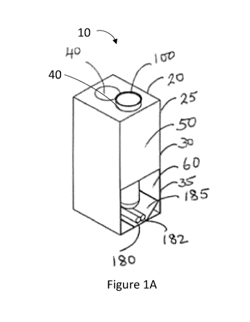
[0037] Referring now to Figures 1A-1C, illustrated therein is an
apparatus 10 for
preparing samples for chemical analysis, in accordance with an embodiment. The
apparatus 10 comprises at least one removable sample container 100 for holding
a
sample 400, and a container receptacle 20 (digester unit) for receiving the at
least one
sample container 100.
[0038] The sample container 100 may include a removable sample container
stopper 22 for enclosing the sample container 100. The sample container 100 is
tapered
towards the bottom and has a narrow elongated protrusion at the bottom, which
typically
defines a crucible portion 152 of the sample container 100. The crucible
portion 152
serves as a hot reaction chamber for digesting, dissolving or otherwise
preparing
samples for chemical analysis. At the same time, an upper larger chamber of
the
sample container defines an expansion portion 150 of the sample container.
[0039] The container receptacle 20 generally includes a compartment or
housing
25, which has an upper block 30 on the top of the housing 25 that is shaped to
receive
or otherwise accommodate the sample container 100 and which defines a cooling
compartment 50. Below the upper block 30 is a digester base 35, which defines
a
heating compartment 60 of the housing 25. The upper block 30 of the housing 25
has
first and second cavities 40 to receive first and second sample containers
100. The
upper block 30 and the digester base 35 may be generally rectangular. The
cavity 40
may be generally cylindrical to receive the sample container 100 that is
generally
cylindrical.
[0040] The heating compartment 60 includes one or more infrared systems
180,
with an infrared heating tube 182 for emitting infrared heat to the sample 400
when the
sample container 100 is received within the housing 25. In the illustrated
embodiment,
the infrared system 180 has an emitter made up an infrared heating tube 182
placed at
the bottom of the digester base 35 within the heating compartment 60. The
infrared
CA 03041117 2019-04-18
WO 2018/072023 PCT/CA2017/051243
- 8 -
system 180 may include two infrared heating tubes 182 fused together.
Underneath the
infrared heating tube 182 is a light reflector plate 185 which is shaped to
focus the
scattered light back to the crucible portion 152 of the sample container 100.
The infrared
heating tube 182 is connected to a controller (described with respect to
Figure 6) for
controlling heat output, and in particular for increasing and maintaining the
temperature
of the sample 400 at a predetermined heating temperature for a predetermined
amount
of time.
[0041] Figures 4A and 4B illustrate the infrared system 180. The infrared
system
180 includes the infrared emitter 182 and the light reflector plate 185 placed
inside the
heating compartment. The controller, power connections and computer systems
with
custom software may also be part of the infrared system 180.
[0042] The infrared system 180 includes a pair of elongated heating tubes
182
that extend along the heating compartment 60 so as to be capable of heating
the
crucible portions 152 of several containers 100 while the sample containers
100 are
received within the housing 25.
[0043] Referring again to Figures 1A-1C, the digester base 35 is shaped
to
receive a crucible portion 152 of the sample container 100, which tapers
downward from
the rest of the tubular body of the sample container 100 and generally forms a
protrusion extending outward from the bottom therefrom. When the sample
container
100 is received within the housing 25 of the container receptacle 20, the
crucible portion
152 sits just above the infrared heating tube 182 with an air gap between the
infrared
heating tube 182 and crucible portion 152 of the sample container. The
crucible portion
152 of the sample container 100 receives the sample 400, and the infrared
emitter 182
directly heats the sample 400 within the crucible portion 152 while the sample
container
100 is received within the housing 25 of the container receptacle 20.
[0044] The upper portion of the container receptacle 20, above the
digester base
35, defines a cooling compartment 50 of the housing 25, which houses a cooling
mechanism 51 such as a condenser coil, Peltier or another suitable cooling
mechanism.
The condenser coil may contain circulating refrigerant, cold water or another
appropriate coolant and may be thermostatically controlled to maintain the
cooling
CA 03041117 2019-04-18
WO 2018/072023 PCT/CA2017/051243
- 9 -
compartment 50 at a predetermined cooling temperature (for example 5-10 C, or
less
than about 0 C). The cooling compartment 50 generally surrounds and generally
cools
the expansion portion 150 of the sample container 100.
The chemical digestion
apparatus 10, may also include a second cooling mechanism for cooling the
heating
compartment 60.
[0045]
The housing 25 also has an insulating region 70 located between the
heating compartment 60 of the digester base 35 and the cooling compartment 50
of the
upper block 30. The insulating region 70 thermally insulates the heating
compartment
60 from the cooling compartment 50. More particularly, the insulating region
70
maintains a cold temperature in the cold zone inside the cooling compartment
50 of the
upper block 30 and maintains a hot temperature in a heating compartment 60 of
the
digester base 35.
[0046]
Figures 2A-2C, illustrates an apparatus 12 for preparing samples for
chemical analysis, in accordance with an embodiment. The apparatus may have a
similar configuration to the apparatus 10 as described in Figures 1A-1C except
for the
infrared system 190.
[0047]
The heating compartment 60 includes one or more infrared systems 190,
including infrared heating tube emitters 191, 192 for directly heating the
sample 400
when the sample container 100 is received within the housing 25. In the
illustrated
embodiment, the infrared system 190 has two independent infrared heating tube
emitters 191 and 192 placed at the bottom of the digester base 35 within the
heating
compartment 60. The infrared heating tubes 191, 192 are spaced apart from each
other
such that when the sample container 100 is placed in the container receptacle
20, the
crucible portion 152 sits just above and in between the infrared heating tubes
191, 192
with an air gap between the emitter and crucible portion of the sample
container.
[0048]
The infrared heating tubes 191, 192 are strategically placed above and
adjacent the light reflector plate 195 which is shaped to focus the scattered
light back to
the crucible portion 152 of the sample container 100. The infrared heating
tubes 191,
192 are positioned on top of the reflector 195 so as to focus the emitted
infrared
radiation to the bottom of the crucible portion 152 of the sample container
100. The
CA 03041117 2019-04-18
WO 2018/072023 PCT/CA2017/051243
- 10 -
infrared heating tubes 191, 192 are connected to a controller (described with
respect to
Figure 6) for controlling heat output, and in particular for increasing and
maintaining the
temperature of the sample 400 at a predetermined heating temperature for a
predetermined amount of time.
[0049] Figures 5A and 5B illustrate the infrared system 190. The infrared
system
190 includes the infrared heating tubes 191, 192 and the reflector plate 195
placed
inside the heating compartment. The controller, power connections and computer
systems with custom software may be part of the infrared system 190.
[0050] The infrared system 190 includes a pair of elongated heating tubes
191,
192 that extend along the heating compartment 60 so as to be capable of
heating the
crucible portions 152 of several containers 100 while the sample containers
100 are
received within the housing 25.
[0051] Referring now to Figures 3A-3C, therein is a sample preparation
system
200, in accordance with an embodiment. The sample preparation system 200
includes
a container apparatus 210 with plurality of single chemical analysis units 227
(as shown
in Figures 1A-1C) for receiving plurality of removable sample containers 300.
The
removable sample containers 300 hold the sample 400, in each sample container
300.
[0052] The sample containers 300 may include removable sample container
stoppers 322 for enclosing each sample container 300. Each sample container
300 is
tapered towards the bottom and has a narrow elongated protrusion at the
bottom, which
typically defines the crucible portion 350 of the sample container. The
crucible portion
serves as a hot reaction chamber for digesting, dissolving or otherwise
preparing
samples for chemical analysis. At the same time, the upper larger chamber of
the
sample container defines an expansion portion 340 of the sample container.
[0053] The container apparatus 210 generally includes a rectangular
compartment or housing 225, which has an upper block 230 on the top of the
housing
225 that is shaped to receive or otherwise accommodate the sample containers
300
and defines a cooling compartment 250. Below the upper block 230 is a digester
base
235, which defines a heating compartment 260 of the housing 225. The upper
block 230
of the housing 225 has a generally cylindrical plurality of cavities 240 to
receive the
CA 03041117 2019-04-18
WO 2018/072023 PCT/CA2017/051243
- 1 1 -
generally cylindrical sample containers 300. The upper block 230 and the
digester base
235 may be generally rectangular.
[0054] The heating compartment 260 includes plurality of infrared systems
290,
each with at least one infrared heating tube 292, for directly heating the
sample 400
when the sample container 300 is received within the housing 225. In the
illustrated
embodiment, each infrared system 290 has an emitter made up of two fused
infrared
heating tubes 292 placed at the bottom of the digester base 235 within the
heating
compartment 260. Underneath and adjacent the infrared heating tube 292 is a
light
reflector plate 295 which is shaped to focus the scattered light back to the
crucible
portion 350 of the sample container 300. The infrared heating tube 292 is
connected to
a controller (described with respect to Figure 6) for controlling heat output,
and in
particular for increasing and maintaining the temperature of the sample 400 at
a
predetermined heating temperature for a predetermined amount of time. The
infrared
heating tube 292 and the light reflector plate 295 placed inside the heating
compartment
along with the controller board makes up the infrared system 290.
[0055] In the illustrated embodiment, there are thirty of the upper block
30 such
infrared systems 290 arranged in a six row by five column configuration within
the
heating compartment 260 of the digester base 235. Single controller board may
be used
to control all infrared systems and may be programmed and operated
simultaneously or
independently. In the illustrated embodiment in Figures 3A-3C, all thirty
upper block 30
infrared systems 290 are arranged within the same heating compartment 260 of
the
digester base 235 in such a way that each infrared system along with each
corresponding to generally rectangle section of the upper block 230 with the
cavity 240
as illustrated in Figures 1A-1C constitutes as one chemical analysis unit 227.
Thus it is
to be understood that in the illustrated embodiment in Figures 3A-3C there are
thirty
upper block 30 such chemical analysis units 227 as illustrated in Figures 1A-
1C exists
for simultaneous sample digestion of a plurality of the samples 400.
[0056] The digester base 235 is shaped to receive crucible portions 350
of
sample containers 300, which tapers downward from the rest of the tubular body
of the
sample container 300 and generally forms a protrusion extending outward from
the
CA 03041117 2019-04-18
WO 2018/072023 PCT/CA2017/051243
- 12 -
bottom therefrom. When the sample containers 300 are received within the
housing 225
of the container apparatus 210, the crucible portion 350 of sample container
300 sits
just above the infrared heating tube 292 with an air gap between the infrared
heating
tube 292 and crucible portion 350 of the sample container 300. The crucible
portion 350
of the sample container 300 receives the sample 400, and the infrared heating
tube 292
directly heats the sample 400 within the crucible portion 350 while the sample
container
300 is received within the housing 225 of the container apparatus 210.
[0057] The upper block 230 of the housing 225 of the container apparatus
210,
above the digester base 235, defines a cooling compartment 250, which houses a
cooling mechanism 251 (shown schematically) such as a condenser coil, Peltier
or
another suitable cooling mechanism. The condenser coil may contain circulating
refrigerant, cold water or another appropriate coolant and may be
thermostatically
controlled to maintain the cooling compartment 250 at a predetermined cooling
temperature (for example 5-10 C, or less than about 0 C). The cooling
compartment
250 generally surrounds the upper part of the cavity 240, and generally cools
the
expansion portion 340 of the sample container 300.
[0058] The housing 225 also has an insulating region 270 located between
the
heating compartment 260 of the digester base 235 and the cooling compartment
250 of
the upper block 230. The insulating region 270 thermally insulates the heating
compartment 260 from the cooling compartment 250. More particularly, the
insulating
region 270 maintains a cold temperature in a cold zone 252 within the cavity
240 of the
upper block 230 and maintains a hot temperature in a heating compartment 260
of the
digester base 235.
[0059] The sample container 300 could be made from quarts or other
materials
such as borosilicate glass (e.g. PyrexTM glass), or clear crystalline
materials. In some
cases, cooling the crucible portion 135 may allow the sample container 300 to
be made
from materials that would otherwise decompose or break-down at temperature
commonly used with hot block digestion.
[0060] The sample container 300 may include one or more graduation
markings
such as a 25mL mark, and a 50mL mark. The markings may assist a technician
when
CA 03041117 2019-04-18
WO 2018/072023 PCT/CA2017/051243
- 13 -
adding the acids, or when adding a liquid to the sample container 300 so as to
prepare
a final volume of sample solution for subsequent chemical analysis.
[0061] In some embodiments, the sample container may also include a bar
code.
This may be useful during atomization of the digestion process.
[0062] When using the sample container 300, the crucible portion 135 may
serve
as a digestion zone or a hot zone where the sample 400 is heated for
digesting,
dissolving or otherwise preparing samples for chemical analysis. Furthermore,
the
expansion portion 340 may serve as a refluxing area or cooled expansion zone
where
vaporized acid and other volatile vapors can initially expand, and then
condense and
reflux back to the crucible portion. This can prevent the loss of acid and
other volatile
components being analyzed. However, some of the unwanted reaction gases may be
separated from the vaporized acid and other volatile vapors and those unwanted
reaction gases can escape through the open mouth of the sample container or if
used a
suitable stopper 522, through the gas escaping holes of stopper place on the
mouth of
the sample container. The stoppers 522 may enclose the expansion portion 340
and
have pinholes therein for allowing condensation in the expansion portion 340
of the
sample container 300.
[0063] Each infrared system 290 is configured to emit infrared radiation
towards
the sample 400 within the crucible portion 350 placed inside the corresponding
chemical
analysis unit 227. The wavelength of the infrared radiation is generally
selected to be
absorbed by the sample 400 so as to heat the sample 400. For example, the
infrared
radiation may have a wavelength of between about 700-nm and about 1-mm. More
particularly, the infrared radiation may have a wavelength of less than about
3-pm, or
more particularly still, less than about 1.4-pm. In some cases, the infrared
radiation may
have a peak energy at about 1¨pm.
[0064] The infrared system 290 includes two fused infrared heating tubes
292 in
one infrared emitter system 290. It is also to be understood that the
embodiment such
as that illustrated in Figures 3A-3C can also be constructed according to unit
described
in Figures 2A-2C using infrared system 190.
CA 03041117 2019-04-18
WO 2018/072023 PCT/CA2017/051243
- 14 -
[0065] The infrared emitter systems are sized and shaped to provide
infrared
radiation to the bottom of the crucible portion 350 of the sample container
300, placed
inside the corresponding chemical analysis unit 227 of the housing 225, having
quartz
tube, ceramic or gold reflectors, halogen or tungsten filaments, and a max
power of
250W. Such infrared emitter tubes are sold by vendors such as Anderson Thermal
Devices Inc. These infrared emitters are capable of emitting short infrared
wavelengths
of about 1.15-pm at peak energy with filament temperatures of up to about 2400
C.
[0066] The illustrated number of samples and configuration is an example
and
that other configurations other than 30 sample in 5x6 configuration are
possible. An
advantage of the system 200 may include the replacement of 30 separate heating
rings
with the five pairs of heating rods.
[0067] The infrared system 290 may be a series of elongated emitter tubes
placed at the bottom of the digester base 235 within the heating compartment
260 and
spaced apart such that each emitter tube sits just below the crucible portion
350 of a
row of sample containers 300 placed within the container receptacle. Thus one
single
infrared emitter tube will provide infrared radiation to a row of the samples
400 placed
inside the crucible portion 350 of the sample containers 300.
[0068] Figure 3B is the cross section view of the container apparatus 210
of the
sample preparation system 200 showing the configuration of the crucible
portions 350 of
a row of sample containers 300 placed above a single infrared emitter system
290
placed at the bottom of the digester base 235, across the length of the row of
the
sample containers.
[0069] The apparatus 200 as illustrated in may include a first cooling
mechanism
251 for cooling the expansion portion 340 of the sample container 300, and if
needed, a
second cooling mechanism 252 for cooling the crucible portion 350 of the
sample
container 300. The first cooling mechanism 251 includes a thermoelectric
cooler such
as a Peltier cooler or coolant liquid circulating system, and the second
cooling
mechanism 252 may include a fan such as a variable speed exhaust fan or
mechanical
ventilation. In other embodiments, the cooling mechanisms could include other
types of
thermoelectric coolers, fans, refrigeration units, heat pumps, and the like,
or
CA 03041117 2019-04-18
WO 2018/072023 PCT/CA2017/051243
- 15 -
combinations thereof. Furthermore, a single cooling mechanism could be used to
cool
both the crucible portion 350 and the expansion portion 340 of all sample
containers
300 placed inside the chemical analysis units 227 of the housing 225 of the
container
apparatus 210 of the sample preparation system 200.
[0070] The first cooling mechanism 251 cools the expansion portion 340 of
the
sample container 300. Cooling the expansion portion 340 of the sample
container 300
can help minimize vaporization by reflux condensation of the acid mixture and
analytes
during digestion of the sample 400. For example, when the sample 400 undergoes
decomposition during digestion, some of the acid or acid mixture and volatile
analytes
may evaporate and rise to the expansion portion 340. The first cooling
mechanism 251
may help condense and reflux these vapors back to the crucible portion 350.
[0071] The first cooling mechanism 251 circulates colder air within the
cooling
compartment 250. For example, the first cooling mechanism within the cooling
compartment 250 may be configured to maintain the cooling compartment 250 at a
desired cooling temperature of, for example, less than about 10 C, or more
particularly,
less than about 5 C. Circulating air within the cavities 240 within the
cooling
compartment 250 can indirectly cool the expansion portion 340 of the sample
container
300.
[0072] In other embodiments, the first cooling mechanism 251 may cool the
expansion portion 340 in other ways, which may include direct or indirect
cooling. For
example, another type of coolant or cooling medium may indirectly cool the
expansion
portion 340 (e.g. using a refrigeration unit). Alternatively, the expansion
portion 340
may be cooled through conductive heat transfer, for example, using a cooling
block, in
which the first cooling mechanism cools the upper block 230, which then cools
the
expansion portion 340. The second cooling mechanism 252 could also use these
and
other cooling techniques.
[0073] Removing heat from the crucible portion 350 of the sample
container 300
can be desirable in order to help maintain the temperature of the acid or acid
mixture
below the boiling point in order to reduce vaporization of the acid or acid
mixture. This
can help reduce escape of vapour as described above. Moreover, less
vaporization can
CA 03041117 2019-04-18
WO 2018/072023 PCT/CA2017/051243
- 16 -
also reduce the amount of cooling for maintaining the expansion portion 340 of
the
sample container 300 at a desired temperature.
[0074] The second cooling mechanism 252 can generally configured to
maintain
the heating compartment 260 at a temperature below the boiling point of the
acid or acid
mixture other liquid reactants. The second cooling mechanism 252 can be
configured to
provide cooling of the heating compartment 260. The cooling can be as
described
above and may simply be a natural air flow through openings, apertures, or
windows
253 in the digester base 235 of the housing 225. The second cooling may be
achieved
simply by the natural flow of room air through the heating compartment 260 of
the
digester base 235 through windows 253 strategically placed on the opposite
walls of the
digester base 235.
[0075] In some embodiments, the second cooling mechanism 252 may be
configured to maintain the heating compartment 260 at a temperature of below
100 C,
or more particularly, near room temperature (e.g. about 20-22 C). This may be
useful
when using the acid, acid mixture or other liquid reactants have boiling
points near
100 C (which is common with aqueous solutions and some acids such as
hydrochloric
acid, nitric acid, and hydrofluoric acid). In other examples, the temperature
may be
higher or lower. For example, sulphuric acid and phosphoric acid have higher
boiling
points near 300 C, and in such cases, the second cooling mechanism 252 may be
configured to maintain the heating compartment 260 at a temperature below 300
C.
[0076] The second cooling mechanism 252 may include one or more fans. For
example, there may be a first fan for removing hot air from the heating
compartment
260, and a second fan for introducing cool air into the heating compartment
260. The
first and second fans may be positioned on opposite sides of the heating
compartment
260 for cooling the crucible portions 350 of the row of sample containers 400.
[0077] The second fan may be configured to draw cool air into the heating
compartment 260 from cooling compartment 250. In such cases, there may be a
third
fan for directing air from the cooling compartment 250 towards the second fan
in the
heating compartment 260. The second cooling mechanism 252 may also be used for
the chemical analysis systems 10, 12, described with reference to Figures 1A-
2C.
CA 03041117 2019-04-18
WO 2018/072023 PCT/CA2017/051243
- 17 -
[0078] Additionally or alternatively, the second fan may be configured to
draw in
cool air from an external source such as room temperature air, or from another
external
source of cool air. In such cases, the container apparatus 210 may have one or
more air
intake apertures or windows 253 extending through the walls of digester base
235 and
into the heating compartment 260.
[0079] As described previously, the infrared system 290 may be selected
to emit
infrared radiation that is absorbed by the sample 400. The infrared radiation
may also
be selected to be partially or completely transmitted through the sample
container 300
and the acid or acid mixture or other sample processing liquid or liquid
mixture. Thus,
the infrared radiation may be selected to directly energize the sample 400
without
appreciably heating the sample container 300 or the liquid therein.
[0080] For example, liquid reactants such as acids and other aqueous
solutions
tend to be more transparent to infrared radiation as compared to microwave
radiation,
particularly for near-infrared and short infrared wavelengths. Accordingly,
infrared
radiation can offer a greater amount of input radiation energy to energize the
sample
400 directly, and thereby initiate chemical transformation of the sample in
the presence
of the liquid reactant (e.g. the acid or acid mixture). Furthermore, excess
thermal energy
released from transformation of the sample 400 to the acid can be removed by
the
second cooling mechanism 252 which may help maintain the temperature of the
acid
below its boiling point.
[0081] Thus, removal of thermal energy from the acid, though against
conventional theories, can enhance sample digestion and can allow more input
energy
to further enhance or speed up the digestion process. In some examples, the
increased
input energy may be equivalent to 800 to 900 C at the surface of the sample
400,
which can provide faster sample decomposition or allow more complete digestion
of
difficult samples. Moreover, in some examples, the infrared heating mechanism
may be
capable of producing temperatures of up to 2000 C at the surface of the sample
400,
which can further enhance sample decomposition.
[0082] In some embodiments, it may be desirable to pressurize the sample
container 300 during digestion. For example, increased pressure in the
crucible portion
CA 03041117 2019-04-18
WO 2018/072023 PCT/CA2017/051243
-18-
350 can increase the boiling points of the acid or other liquids. This can
help reduce
vaporization of both the acid and analytes while also allowing even more input
energy to
the sample 400. Moreover, increased pressure in the expansion portion 340 can
enhance condensation of any vaporized gases.
[0083] In some applications, partial pressure can be achieved through the
use of
the removable stoppers 522 loosely placed on top of the mouth of the sample
containers 300. The removable stopper 322 may be designed such a way to
provide
refluxing condition while allowing slow escape of unwanted gaseous bi-products
produced during the chemical reaction in the crucible portion 350.
[0084] When directly heating the sample 400 with radiation, it may be
desirable
for the crucible portion 350 of the sample container 300 to be substantially
or completely
transparent to the radiation being used to heat the sample 400. For example,
when
using infrared radiation, it may be desirable for the sample container 300 to
be made
from quartz, which is substantially transparent to infrared radiation. This
can help
prevent hot spots on the crucible portion 350, and can also provide more even
heating
to the sample 400.
[0085] In a further embodiment, one or more of the infrared system 290,
may be
moveable lengthwise (e.g., on a track), parallel to the length of the crucible
portion 350
and proximal to the crucible portion 350 of the sample container 300. This may
allow the
infrared heating tube 292 to emit radiation transversely along some of, or the
entirety of
the crucible portion 350. The infrared system 290 could be moved manually or
through
an actuator. As an example, the actuator could be controlled mechanically,
electrically,
or through computer software.
[0086] The angular direction of the infrared system 290 rods could also
be
controlled with the reflector 295, for example, to focus radiation at a narrow
region or
disperse radiation over a wider region. In some embodiments, the region may
range
from 5mm-10mm of the bottom curvature of the crucible portion 350 or from 5-mm
to
45-mm in length along the crucible portion 350. The angular direction of the
radiation
may be adjusted using a gold coating on the reflector 295, or using another
reflective
CA 03041117 2019-04-18
WO 2018/072023 PCT/CA2017/051243
- 19 -
material such as quartz powder or a ceramic. The reflector 295 may be located
on or
near the infrared system 290.
[0087] Figure 6 illustrates the system 200 schematically, in accordance
with an
embodiment. The system 200 includes a controller 500 for operating the
infrared
system 290. The controller 500 may control and adjust continuously and/or
separately
the output power of the infrared emitters 290. This may allow the sample to
reach a
desired heating temperature for sample digestion. The heating time may also be
controlled.
[0088] In addition to controlling the infrared system 290, the controller
500 may
also control other components of the sample preparation system 200 such as
other
cooling mechanisms, 251, 252 including the Peltier cooler of the first cooling
mechanism in the cooling compartment 250. Thus, the controller can be used to
control
temperatures in both the heating compartment 260 and the cooling compartment
250.
[0089] The controller 500 can also be configured to control cool-down
times. For
example, the controller 500 may activate the first or second cooling
mechanisms 251,
252 after sample digestion is complete in order to cool down the sample
container 300.
This can allow users to pick up and handle the sample container 300 after
digestion. In
some cases, the cool-down time may be about 1-minute in comparison to 4-hours
or
more for hot block digestion devices.
[0090] The infrared system 290 may be configured to emit near-infrared
wavelengths (e.g. 0.75-pm to 1.4-pm), short infrared wavelengths (e.g. 1.4-pm
to 3-pm),
medium infrared wavelengths (e.g. 3-pm to 8-pm), long infrared wavelengths
(e.g. 8-pm
to 15-pm), far-infrared wavelengths (e.g. 15-pm to 1000-pm), or combinations
thereof.
The controller 500 may select a specific infrared wavelength, for example,
depending on
the type of sample being digested or other aspects of the digestion being
performed.
For example, when the sample container 300 is made of quartz and the acids
used are
water-based, it may be desirable to select near-infrared wavelengths and short
infrared
wavelengths because quartz and water tend to have low absorption coefficients
at these
wavelengths. Thus, these wavelengths tend to allow more infrared radiation to
be
transmitted to the sample 400.
CA 03041117 2019-04-18
WO 2018/072023 PCT/CA2017/051243
- 20 -
[0091] The controller 500 may also control the output energy of the
infrared
system 290. This may help maintain the sample 400 at a particular temperature
for a
particular time, for example, depending on the type of sample being digested
or other
aspects of the digestion being performed.
[0092] In view of the above, one or more embodiments herein may be capable
of
enhancing chemical dynamics of the digestion process, which can help achieve
faster
or more complete digestion. Volatile analyte and reactants can also be
preserved, which
can lead to better recovery of analyte elements of interest.
[0093] While the above description provides examples of one or more
apparatus,
methods, or systems, it will be appreciated that other apparatus, methods, or
systems
may be within the scope of the claims as interpreted by one of skill in the
art.