Note: Descriptions are shown in the official language in which they were submitted.
CA 03041133 2019-04-18
WO 2018/072026
PCT/CA2017/051246
SYSTEM AND METHOD FOR MAGNETIC FIELD CONTROL IN A WELD REGION
CROSS-REFERENCE TO RELATED APPLICATIONS
[0001] The present application claims the benefit of United States Provisional
Patent
Application No. 62/410,602 filed on October 20, 2016, the contents of which
are hereby
incorporated in their entirety by reference.
TECHNICAL FIELD
[0002] The present disclosure relates to systems and methods for controlling
the magnetic
field in a weld region where high ambient magnetic fields are present.
BACKGROUND OF THE ART
[0003] Industrial processes used to extract metals, such as aluminum welding,
typically
employ large currents, which cause local magnetic fields greater than 50
Gauss. However,
the high ambient magnetic field environment affects electric arcs that result
from such
welding operations, leading to arc instability and low quality welds. Welding
repair work is
therefore frequently required, which increases costs and reduces efficiency.
[0004] Several methods have been proposed to overcome the known challenge of
arc
instability in high ambient magnetic field welding environments. One method
involves
positioning an excited coil adjacent the welding head to lower the ambient
magnetic field
and stabilize the electric arc at the weld position. However, this method
generates parasitic
forces on the welding head and negatively impacts the welder's ergonomics. The
ability to
reorient the magnetic fields is also limited, thus decreasing the overall
efficiency of the
process. Other proposed systems and methods require bulky and expensive
hardware
components to achieve arc stability, thus proving time consuming, cumbersome,
and
unsuitable for use on the field.
[0005] There is therefore a need to address the problem of arc instability
during welding
operations.
SUMMARY
[0006] The present disclosure describes the use of a permanent magnet for
controlling
magnetic fields, and accordingly weld arcs, during welding operations
performed in high
magnetic field environments (e.g. greater than 50 Gauss). The permanent magnet
creates
- 1 -
CA 03041133 2019-04-18
WO 2018/072026
PCT/CA2017/051246
a low magnetic field zone in the weld region, thereby improving the quality of
resulting
welds.
[0007] In accordance with a first broad aspect, there is provided an arc
welding system
comprising a welding apparatus configured to be displaced along a welding path
in a weld
region and to perform an arc weld along the welding path, and at least one
permanent
magnet provided adjacent the welding apparatus and configured for displacement
therewith along the welding path, the at least one permanent magnet configured
to
generate a nulling magnetic field that opposes an ambient magnetic field
present in the
weld region.
[0008] In some embodiments, the system further comprises a support member
configured
to support the welding apparatus and the at least one permanent magnet thereon
and to
position the welding apparatus and the at least one permanent magnet adjacent
a surface
on which the arc weld is to be performed.
[0009] In some embodiments, the welding apparatus is configured to be
displaced along a
non-longitudinal welding path.
[0010] In some embodiments, the welding apparatus is configured to be
displaced along a
longitudinal welding path and the support member comprises a stationary
guiding rail
extending along an axis substantially parallel to the longitudinal welding
path and a frame
releasably attached to the guiding rail and configured for linear movement
relative thereto
along the axis, the frame configured to support the welding apparatus and the
at least one
permanent magnet thereon.
[0011] In some embodiments, the support member comprises a first arm and a
second
arm, the welding apparatus configured to be secured to the first arm and the
at least one
permanent magnet configured to be secured to the second arm.
[0012] In some embodiments, the first arm and the second arm are articulated
and at least
one of an axial position and an angular position of a given one of the welding
apparatus
and the at least one permanent magnet relative to the surface is adjusted by
adjusting a
positioning of a corresponding one of the first arm and the second arm.
- 2 -
CA 03041133 2019-04-18
WO 2018/072026
PCT/CA2017/051246
[0013] In some embodiments, the system further comprises a sensing device
adapted to
be positioned in place of the welding apparatus prior to the arc weld being
performed and
configured for displacement with the at least one permanent magnet along the
welding
path, the sensing device configured to measure a direction and a magnitude of
the
ambient magnetic field for determining a position of the at least one
permanent magnet
that achieves a desired level of attenuation of the ambient magnetic field.
[0014] In some embodiments, the at least one permanent magnet comprises one
permanent magnet.
[0015] In some embodiments, the at least one permanent magnet comprises two
permanent magnets, a longitudinal axis of a first one of the two permanent
magnets at an
angle relative to a longitudinal axis of a second one of the two permanent
magnets.
[0016] In some embodiments, the at least one permanent magnet comprises four
permanent magnets having their longitudinal axes at an angle relative to one
another.
[0017] In some embodiments, the angle is comprised between 60 and 120 degrees.
[0018] In some embodiments, the angle is 90 degrees such that the longitudinal
axes of
the permanent magnets are substantially perpendicular to one another.
[0019] In accordance with a second broad aspect, there is provided a method
for
controlling an ambient magnetic field present in a weld region where an arc
weld is to be
performed along a welding path using a welding apparatus. The method comprises
positioning a permanent magnet adjacent the weld region, the permanent magnet
adapted
for movement along the welding path synchronously with the welding apparatus
and
configured to generate a nulling magnetic field that opposes the ambient
magnetic field,
measuring the ambient magnetic field as the permanent magnet advances along
the
welding path, comparing the measured ambient magnetic field to a magnetic
field
threshold, and, if the measured ambient magnetic field is not within the
magnetic field
threshold, causing a position of the permanent magnet to be adjusted to bring
the
measured ambient magnetic field within the magnetic field threshold.
[0020] In some embodiments, a method for controlling an ambient magnetic field
present
in a weld region where an arc weld is to be performed along a welding path
using a
- 3 -
CA 03041133 2019-04-18
WO 2018/072026
PCT/CA2017/051246
welding apparatus, the method comprising positioning at least one permanent
magnet
adjacent the weld region, the at least one permanent magnet adapted for
movement along
the welding path synchronously with the welding apparatus and configured to
generate a
nulling magnetic field that opposes the ambient magnetic field, acquiring a
measurement
of the ambient magnetic field as the at least one permanent magnet advances
along the
welding path, comparing the measured ambient magnetic field to a threshold,
and
responsive to determining that the measured ambient magnetic field is not
within the
threshold, causing a position of the at least one permanent magnet to be
adjusted to bring
the measured ambient magnetic field within the threshold.
[0021] In some embodiments, positioning the at least one permanent magnet
comprises
positioning one permanent magnet adjacent the weld region.
[0022] In some embodiments, positioning the at least one permanent magnet
comprises
positioning two permanent magnets adjacent the weld region, a longitudinal
axis of a first
one of the two permanent magnets at an angle relative to a longitudinal axis
of a second
one of the two permanent magnets.
[0023] In some embodiments, positioning the at least one permanent magnet
comprises
positioning adjacent the weld region four permanent magnets having their
longitudinal
axes at an angle relative to one another.
[0024] In some embodiments, the angle is comprised between 60 and 120 degrees.
[0025] In some embodiments, the angle is 90 degrees such that the longitudinal
axes of
the permanent magnets are substantially perpendicular to one another.
[0026] In some embodiments, the measurement of the ambient magnetic field is
acquired
from a sensing device adapted to be positioned in place of the welding
apparatus prior to
the arc weld being performed and configured for displacement with the at least
one
permanent magnet along the welding path, the sensing device configured to
measure a
direction and a magnitude of the ambient magnetic field.
[0027] In some embodiments, the at least one permanent magnet is configured to
be
secured to at least one articulated arm of a support member and causing a
position of the
at least one permanent magnet to be adjusted comprises adjusting a positioning
of the at
- 4 -
CA 03041133 2019-04-18
WO 2018/072026
PCT/CA2017/051246
least one arm for adjusting at least one of an axial position and an angular
position of the
at least one permanent magnet relative to a surface on which the arc weld is
to be
performed.
[0028] In some embodiments, the at least one permanent magnet comprises at
least two
magnets and causing a position of the at least one permanent magnet to be
adjusted
comprises adjusting at least one of a spacing between the at least two magnets
and an
angle between longitudinal axes of the at least two magnets.
[0029] In accordance with a third broad aspect, there is provided a system for
controlling
an ambient magnetic field present in a weld region where an arc weld is to be
performed
along a welding path using a welding apparatus, the system comprising a
memory, a
processor, and at least one application stored in the memory and executable by
the
processor for outputting a first control signal comprising instructions for
causing at least
one permanent magnet to be positioned adjacent the weld region, the at least
one
permanent magnet adapted for movement along the welding path synchronously
with the
welding apparatus and configured to generate a nulling magnetic field that
opposes the
ambient magnetic field, acquiring a measurement of the ambient magnetic field
as the at
least one permanent magnet advances along the welding path, comparing the
measured
ambient magnetic field to a threshold, and responsive to determining that the
measured
ambient magnetic field is not within the threshold, outputting a second
control signal
comprising instructions for causing a position of the at least one permanent
magnet to be
adjusted to bring the measured ambient magnetic field within the threshold.
[0030] In some embodiments, the at least one application is executable by the
processor
for positioning the at least one permanent magnet comprising positioning one
permanent
magnet adjacent the weld region.
[0031] In some embodiments, the at least one application is executable by the
processor
for positioning the at least one permanent magnet comprising positioning two
permanent
magnets adjacent the weld region, a longitudinal axis of a first one of the
two permanent
magnets at an angle relative to a longitudinal axis of a second one of the two
permanent
magnets.
- 5 -
CA 03041133 2019-04-18
WO 2018/072026
PCT/CA2017/051246
[0032] In some embodiments, the at least one application is executable by the
processor
for positioning the at least one permanent magnet comprising positioning
adjacent the
weld region four permanent magnets having their longitudinal axes at an angle
relative to
one another.
[0033] In some embodiments, the angle is comprised between 60 and 120 degrees.
[0034] In some embodiments, the angle is 90 degrees such that the longitudinal
axes of
the permanent magnets are substantially perpendicular to one another.
[0035] In some embodiments, the at least one application is executable by the
processor
for acquiring the measurement of the ambient magnetic field from a sensing
device
adapted to be positioned in place of the welding apparatus prior to the arc
weld being
performed and configured for displacement with the at least one permanent
magnet along
the welding path, the sensing device configured to measure a direction and a
magnitude of
the ambient magnetic field.
[0036] In some embodiments, the at least one permanent magnet is configured to
be
secured to at least one articulated arm of a support member and the at least
one
application is executable by the processor for causing a position of the at
least one
permanent magnet to be adjusted comprising adjusting a positioning of the at
least one
arm for adjusting at least one of an axial position and an angular position of
the at least
one permanent magnet relative to a surface on which the arc weld is to be
performed.
[0037] In some embodiments, the at least one permanent magnet comprises at
least two
magnets and further the at least one application is executable by the
processor for causing
a position of the at least one permanent magnet to be adjusted comprising
adjusting at
least one of a spacing between the at least two magnets and an angle between
longitudinal axes of the at least two magnets.
[0038] In accordance with a fourth broad aspect, there is provided a computer
readable
medium having stored thereon program code executable by a processor for
controlling an
ambient magnetic field present in a weld region where an arc weld is to be
performed
along a welding path using a welding apparatus, the program code executable
for
outputting a first control signal comprising instructions for causing at least
one permanent
magnet to be positioned adjacent the weld region, the at least one permanent
magnet
- 6 -
CA 03041133 2019-04-18
WO 2018/072026
PCT/CA2017/051246
adapted for movement along the welding path synchronously with the welding
apparatus
and configured to generate a nulling magnetic field that opposes the ambient
magnetic
field, acquiring a measurement of the ambient magnetic field as the at least
one
permanent magnet advances along the welding path, comparing the measured
ambient
magnetic field to a threshold, and responsive to determining that the measured
ambient
magnetic field is not within the magnetic field threshold, outputting a second
control signal
comprising instructions for causing a position of the at least one permanent
magnet to be
adjusted to bring the measured ambient magnetic field within the threshold.
BRIEF DESCRIPTION OF THE DRAWINGS
[0039] Further features and advantages of the present invention will become
apparent
from the following detailed description, taken in combination with the
appended drawings,
in which:
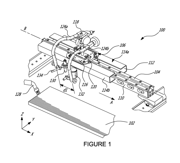
[0040] Figure 1 is a schematic perspective view of a system for magnetic field
control in a
weld region where high ambient magnetic fields are present, in accordance with
an
illustrative embodiment;
[0041] Figure 2 is a detailed view of the system of Figure 1;
[0042] Figure 3 is a schematic diagram of the magnetic fields generated during
welding
using the system of Figure 1;
[0043] Figure 4 is a schematic perspective view of a measuring device, in
accordance with
an illustrative embodiment;
[0044] Figure 5 is a detailed view of the sensing probe of Figure 1;
[0045] Figure 6A illustrates an exemplary setup for obtaining a magnetic field
measurement at a vertical weld bead using the system of Figure 1;
[0046] Figure 6B illustrates an exemplary setup for controlling the ambient
magnetic field
adjacent the vertical weld bead of Figure 6A, in accordance with a first
illustrative
embodiment;
[0047] Figure 7A illustrates an exemplary setup for performing a welding
operation on the
vertical weld bead of Figure 6A;
- 7 -
CA 03041133 2019-04-18
WO 2018/072026
PCT/CA2017/051246
[0048] Figure 7B illustrates an exemplary setup for performing a horizontal
weld bead
using the system of Figure 1;
[0049] Figure 8 illustrates an exemplary setup for controlling the ambient
magnetic field
adjacent a weld bead, in accordance with another illustrative embodiment;
[0050] Figure 9A, Figure 9B, Figure 9C, and Figure 9D illustrate work areas
achieved
around one, two, and four more permanent magnets, in accordance with an
illustrative
embodiment;
[0051] Figure 10 is a flowchart of a method for magnetic field control in a
weld region
where high ambient magnetic fields are present, in accordance with an
illustrative
embodiment; and
[0052] Figure 11 is a block diagram of a control system for magnetic field
control in a weld
region where high ambient magnetic fields are present, in accordance with an
illustrative
embodiment.
[0053] It will be noted that throughout the appended drawings, like features
are identified
by like reference numerals.
DETAILED DESCRIPTION
[0054] Referring to Figure 1 and Figure 2, a system 100 for magnetic field
control in a
weld region where high ambient magnetic fields are present will now be
described. The
system 100 may be used for controlling electric arcs produced when performing
welding
operations on a workpiece 102. In one embodiment, the system 100 is used in
aluminum
arc welding (e.g. smelting) processes, such as Metal Inert Gas (MIG) welding
processes,
Tungsten Inert Gas (TIG) welding processes, or the like. In the illustrated
embodiment, the
workpiece 102 is an elongate piece of aluminum that is welded along a welding
path or
direction A, which is substantially parallel to the x-axis. As such,
longitudinal arc welds (not
shown) can be obtained. The system 100 may be used to perform angle welding
and end-
to-end welding. It should however be understood that the system 100 may be
used for
other welding applications and that non-longitudinal arc welds may be
performed. In this
case, the system 100 may be used to weld the workpiece 102 along a non-
longitudinal
path. It should also be understood that, although the workpiece 102 is
illustrated herein as
- 8 -
CA 03041133 2019-04-18
WO 2018/072026
PCT/CA2017/051246
being formed of a single piece of material, the workpiece 102 may comprise two
separate
pieces of material having abutted edges that define a joint to be welded.
Different arc
welding positions may also apply. For example, the weld bead may be vertical
(i.e. extend
along the z-axis) or horizontal (i.e. extend along the x-axis) and the welding
direction A
may accordingly extend along the z-axis or the x-axis (as illustrated). The
arc welding
position may also be flat or overhead. Moreover, although the workpiece 102 is
illustrated
as being a substantially planar elongate piece of material, other shapes may
apply.
[0055] The system 100 illustratively comprises a stationary guiding rail 104,
which is
configured to be positioned (e.g. using suitable support means, not shown)
adjacent the
workpiece 102 to be welded, at a distance that facilitates welding to be
performed on the
workpiece 102. The guiding rail 104 extends along a longitudinal axis B, which
is
substantially parallel to the welding direction A. A frame 106 is releasably
attached to the
rail 104 and adapted for linear movement relative to the rail 104. For this
purpose, a linear
movement mechanism, such as a linear bearing mechanism, or the like may be
used. In
one embodiment, a plurality of wheels (reference 108 in Figure 2) are
positioned adjacent
opposite edges 110 of the rail 104. The wheels 108 are configured to cooperate
with and
be retained by an inner surface (reference 112 in Figure 2) of the frame 106.
A motor (not
shown) or other suitable driving means may be provided to cause axial
displacement of
the frame 106 relative to the guiding rail 104. It should however be
understood that any
suitable mechanism enabling sliding movement of the frame 106 relative to the
rail 104
may be used. A pair of elongated U-shaped protecting members 114a, 114b may
further
be provided to protect the rail 104 from aluminum particles that may be
generated by the
welding processes. For this purpose, each member 114a, 114b may be attached to
the
frame 106 and extend along the axis B so as to be positioned adjacent a
corresponding
edge 110 of the guiding rail 104.
[0056] The frame 106 illustratively comprises a substantially planar support
member 116,
such as a plate or the like, that supports thereon a rod 118, which extends
away from the
support member 116 along the z axis. In one embodiment, a plate 120, which is
connected
to an end portion (not shown) of the rod 118, is illustratively attached to
the support
member 116 via a plurality of threaded apertures (not shown) formed in the
plate 120. The
apertures formed in the plate 120 are adapted to be aligned and cooperate with
a plurality
of corresponding threaded apertures as in 122 formed in the support member
116.
- 9 -
CA 03041133 2019-04-18
WO 2018/072026
PCT/CA2017/051246
Suitable attachment means (not shown), such as screws, bolts, nuts, and the
like, may
then be received in the aligned apertures for attaching the plate 120, and
accordingly the
rod 118, to the support member 116. In one embodiment, the support member 116
is
provided with a plurality of apertures 122, which are positioned at various
positions along
the y axis. The axial position of the plate 120 along the y axis, and
accordingly that of the
rod 118, can then be adjusted (see arrow C) by selecting given ones of the
apertures 122
to be used for attaching the plate 120 to the support member 116.
[0057] Still referring to Figure 1 and Figure 2, the support member 116
comprises a first
arm 124a and a second arm 124b, which are attached to the rod 118 using
suitable
attachment means (reference 125 in Figure 2). Each arm 124a, 124b comprises a
first end
portion 126a, which is secured to the rod 118 via the attachment means 125,
and a
second free end portion 126b that extends away from the arm 124a, 124b and
towards the
workpiece 102. In one embodiment, the arms 124a, 124b are articulated and
curved
members that are secured to the support member 116 so as to be spaced from one
another. The attachment means 125 enables axial movement of a corresponding
arm
124a, 124b relative to the rod 118 so as to allow adjustment of the vertical
position (along
the z axis) of the arm 124a, 124b. Accurate positioning of each arm 124a, 124b
can then
be achieved by suitably articulating (e.g. stretching or contracting) the arm
124a, 124b, in
addition to adjusting the attachment means 125. Once the position is adjusted,
the arm
124a, 124b may be locked in place using a suitable locking means, such as a
nut (not
shown). In particular, the position of the arms 124a, 124b may be adjusted in
accordance
with the type of weld bead to be achieved and in order to cancel the high
ambient
magnetic field and ensure adequate ergonomics for the welder. In some
embodiments, the
arms 124a, 124b may be positioned so as to be substantially parallel to one
another and
spaced by a fixed distance dl, as illustrated in Figure 1 and Figure 2. In
this embodiment,
the second free end portions 126b of both arms 124a, 124b extend along an axis
D. It
should however be understood that, in other embodiments, the arms 124a, 124b
may not
be parallel to one another.
[0058] In one embodiment, the protecting members 114a and 114b are made of
rubber,
the rail 104, the rod 118, the plate 120, and the support member 116 are made
of stainless
steel, and the arms 124a, 124b are made of steel. It should however be
understood that
other suitable materials may apply.
-10-
CA 03041133 2019-04-18
WO 2018/072026
PCT/CA2017/051246
[0059] Still referring to Figure 1 and Figure 2, a welding head (reference 128
in Figure 1)
is illustratively used to weld the workpiece (reference 102 in Figure 1). In
one embodiment,
prior to using the welding head 128, a sensing device (e.g. a probe) 130 may
first be used
in cooperation with at least one permanent magnet (e.g. magnet 132) to reduce
the local
ambient magnetic field. In particular and as will be discussed further below,
the sensing
probe 130 may be used to measure the local ambient magnetic field at the weld
region
(i.e. the magnetic field that will affect the electric arc generated by the
welding head 128
once the welding operation proceeds) and accordingly determine the magnet's
position
that will suitably cancel the local magnetic field. Once the desired position
of the magnet
132 has been determined, the welding head 128 may be positioned in place of
the sensing
probe 130 and the welding operation may proceed.
[0060] Still referring to Figure 2, the sensing probe 130 is illustratively
secured to the
second end portion 126b of the first arm 124a (using an attachment means
131a). The
permanent magnet 132 is illustratively secured to the second end portion 126b
of the
second arm 124b (using an attachment means 131b). The attachment means 131a
may
be configured for rotation about a rotary axis El while the attachment means
131b may be
configured for rotation about a rotary axis E2. Rotation about the y axis may
also be
achieved. In this manner, by rotating the attachment means 131a, 131b, the
angular
position (i.e. the orientation) of the sensing probe 130 (and accordingly of
the welding
head 128 to be positioned in place of the sensing probe 130 once the desired
magnet
position has been determined) and of the magnet 132 relative to a surface (not
shown) of
the workpiece 102 can be adjusted accordingly. In one embodiment, the welding
head
128, the sensing probe 130, and the magnet 132 are oriented so as to extend
along a
direction, which is substantially perpendicular to the axis B. It should
however be
understood that the angular positioning (i.e. the orientation) of the welding
head 128, the
sensing probe 130, and the magnet 132 may be adjusted in accordance with the
welding
operation being performed. In particular, the position of the sensing probe
130 relative to
the permanent magnet 132 (and accordingly the angle between the axes El, E2)
depends
on the angle between the ambient magnetic field and the weld bead, as well as
on the
constraints of the weld bead (e.g. T-shaped or end-to-end weld bead).
[0061] The sensing probe 130 illustratively comprises a semiconductor device
(not
shown), which is responsive to local magnetic fields that arise in the
vicinity of the weld
-11-
CA 03041133 2019-04-18
WO 2018/072026
PCT/CA2017/051246
region. The flux of the local ambient magnetic field can be seen as a
plurality of concentric
circles (see dashed lines in Figure 3) in the plane of the workpiece 102. Upon
detecting
the local magnetic field, the semiconductor device outputs an electrical
voltage, which is
proportional to the strength and polarity of the local magnetic field. The
output voltage is
then detected by a suitable measuring device (not shown) as the sensing probe
130
passes along the weld bead and a corresponding reading of the magnitude and
direction
of the local magnetic field is produced. In one embodiment, the semiconductor
device is a
three-axis probe adapted to measure magnetic fields in all directions (i.e.
the x, y, and z
directions). Examples include, but are not limited to, a Hall-effect probe,
such as a
Gaussmeter. It should however be understood that any other suitable probe may
apply.
[0062] Figure 4 illustrates a measuring device 200 adapted to receive the
output voltage
measured by the sensing probe 130 and accordingly detect the magnitude and
direction
(i.e. the strength and polarity) of the local magnetic field. The device 200
may be secured
to the system 100 using a suitable attachment means 202. Alternatively, the
device 200
may be handheld. The device 200 is adapted to receive via a suitable input
means, such
as a cable 204, input data from the sensing probe 130, the input data
indicative of the
output voltage measured as the probe 130 passes along the weld bead. The
device 200
then computes the corresponding magnitude and direction of the local magnetic
field and
outputs the computed data to a suitable output means, such as a screen 206. In
one
embodiment, after use, the sensing probe 130 may be secured to the device 200
using a
suitable attachment means, such as a grommet 208 extending away from an outer
surface
(not shown) of the device 200 and adapted to receive and retain the probe 130
therein.
Other attachment means may apply.
[0063] Referring back to Figure 2 and Figure 3, the magnet 132 is
illustratively provided in
its neutral state (i.e. with null magnetization) and is shaped as a cylinder.
In one
embodiment, the magnet 132 has a diameter of two (2) inches and a length of
two (2)
inches, with a magnetic strength of 3500 Gauss at a surface thereof. Other
shapes (e.g.
rectangle), dimensions, and magnetic strengths may apply. For example, a
rectangular
magnet may be used to improve the welder's ergonomics, e.g. increase the
welder's work
area (or volume) along the z axis. For a given magnetic field to be
compensated, as used
herein, the term 'work area' (or 'work volume') refers to a space in which the
magnitude of
the magnetic field has an upper bound substantially equal to the magnitude of
the
- 12-
CA 03041133 2019-04-18
WO 2018/072026
PCT/CA2017/051246
magnetic field to be compensated plus 100 Gauss and a lower bound
substantially equal
to the magnetic field to be compensated minus 100 Gauss. In this manner, the
magnetic
field generated by the permanent magnet(s) is substantially unidirectional in
the work area.
In one embodiment, it is desirable for the work area to be greater than 14 mm,
and
preferably about 30 mm.
[0064] As understood by those skilled in the art, the permanent magnet 132 is
made from
ferromagnetic material, including but not limited to oxides (e.g. iron,
nickel, cobalt, barium,
strontium, or the like), alloys(s) (e.g. alnico, rare earth metals such as
samarium,
neodymium, or the like), and bonded material (e.g. magnetic materials powdered
and/or
mixed with plastic or rubber and molded). It should be understood that the
characteristics
of the magnet 132 may be selected in accordance with the welding application
as well as
the desired level of magnetic field attenuation to be achieved, as will be
discussed further
below.
[0065] The permanent magnet 132 has a first face 133a defining a north pole
and a
second face 133b opposite the first face 133a, the second face 133b defining
the south
pole of the permanent magnet 132, the faces 133a, 133b extending along planes
substantially transverse to a longitudinal axis (not shown) of the magnet 132.
A persistent
magnetic field is created between the north and south poles of the permanent
magnet 132.
As understood by those skilled in the art, the magnetic field lines (see
arrows between the
north and south poles in Figure 3) point away from the magnet's north pole and
towards
the south pole. The magnetic field created by the permanent magnet 132
therefore
opposes the local ambient magnetic field, thereby reducing the local ambient
magnetic
field.
[0066] Referring now to Figure 5 in addition to Figure 1 and Figure 2, the
sensing probe
130 (and subsequently the welding head 128) may be secured to the arm 124a
using a
first elongate support member 134 that extends along a direction F, which is
in one
embodiment substantially perpendicular to axis D. The sensing probe 130 may be
retained
within a second tubular support member 136, which is connected to the first
support
member 134 using a suitable adaptor 138. An opening (not shown) is
illustratively formed
in the adaptor 138, which has a threaded inner surface (not shown) that is
adapted to
cooperate with a threaded outer surface 140 provided on the second support
member 136.
-13-
CA 03041133 2019-04-18
WO 2018/072026
PCT/CA2017/051246
In this manner, the second support member 136 is received and retained in the
adaptor
138, which is in turn connected to the first support member 134. A bottom
portion (not
shown) of the sensing probe 130 then extends away from the adaptor 138 by a
predetermined distance d2, which is selected such that the electric arc, which
is generated
during the welding operation (upon the welding head 128 being positioned in
place of the
sensing probe 130), is created at a tip 142 of the second support member 136.
[0067] In operation, as the frame 106 is driven along the welding path A, the
sensing
probe 130 and the permanent magnet 132 are moved synchronously adjacent the
workpiece 102, with magnet 132 being ahead of the sensing probe 130 by the
distance dl.
As discussed above, the permanent magnet 132, which is positioned adjacent the
weld
region (not shown), generates a counterbalancing or nulling magnetic field
that offsets the
high ambient magnetic field present in the weld region. In this manner, the
local ambient
magnetic field in the weld region is compensated for and reduced, thereby
creating a low
magnetic field zone at the weld region. Welding can therefore be facilitated
and high
quality (e.g. in terms of uniformity, porosity) welds obtained. In one
embodiment, the local
ambient magnetic field is reduced to a predetermined threshold, the threshold
value being
selected such that the local ambient magnetic field is sufficiently attenuated
to stabilize the
electric arc and facilitate welding.
[0068] As discussed above, the position and orientation of the permanent
magnet 132
relative to the workpiece 102 can be selected for adjusting the desired level
of magnetic
field attenuation while facilitating access to and visibility of the weld
region. Indeed, by
rotating the attachment means (reference 131b in Figure 2) to which the
permanent
magnet 132 is secured, the angular position of the permanent magnet 132
relative to the z
axis, and accordingly to the electric arc, can be varied. By selecting
appropriate apertures
(reference 122 in Figure 2) for securing the rod 118 to the support member
116, the
horizontal position (along they axis) of the permanent magnet 132 can also be
varied. In
addition, the vertical position (along the z axis) of the permanent magnet 132
can be
adjusted using the attachment means (reference 125) that secures the arm 124b
to the rod
118. The permanent magnet 132 can therefore be positioned closer or further
away from
the weld region. In this manner, it is possible to vary the magnitude and
polarity of the
magnetic field generated by the permanent magnet 132. A desired level of
magnetic field
attenuation can therefore be achieved by adjusting the positioning of the
permanent
- 14-
CA 03041133 2019-04-18
WO 2018/072026
PCT/CA2017/051246
magnet 132 relative to the electric arc. For example, using the system 100, a
magnetic
field between about 25 and 30 Gauss can be achieved. It should be understood
that other
magnetic field attenuation levels may apply.
[0069] As discussed above, the sensing probe 130 measures the local magnetic
field
adjacent the weld bead and accordingly determines the position of the magnet
132 that
allows to achieve the level of magnetic field attenuation most suitable for
the welding
operation at hand. In one embodiment, a magnetic field of substantially zero
Gauss is
desired. Once the position and orientation that achieves the desired level of
magnetic field
attenuation has been determined and the magnet 132 placed in this position and
orientation, the sensing probe 130 may be removed from the system 100 and the
welding
head 128 positioned in its place. The welding operation may then proceed at
the low
ambient magnetic field. This is illustrated in Figure 6A, Figure 6B, and
Figure 7A, which
illustrate an exemplary welding setup 300. Figure 6A illustrates that a
magnetic field
measurement of 272.10 Gauss may be obtained using a measuring unit 302, when
no
magnetic field control mechanism is in place. The measuring unit 302 receives
the
magnetic field measurement from a sensing probe 304 positioned (on an
articulated arm
306) adjacent a vertical weld bead 308. Figure 6B illustrates that suitably
positioning a
permanent magnet 310 adjacent the weld region allows to significantly reduce
the local
magnetic field. Indeed, a magnetic field measurement of 17.67 Gauss is
obtained from the
sensing probe 304. It should be understood that the magnet position and/or
orientation
may be adjusted a number of times prior to achieving the reading of 17.67
Gauss, which in
the illustrated example corresponds the desired level of magnetic field
attenuation. As
shown in Figure 7A, once the magnet position and/or orientation, which
achieves the
desired magnetic field attenuation, have been determined, the welding head 312
may be
positioned in place of the sensing probe (reference 304 in Figure 6A), i.e.
attached to the
arm 306, and the welding operation performed as needed. As discussed above,
using the
system 100 of Figure 1, both vertical and horizontal weld beads may be
performed at low
magnetic field levels. Figure 7B illustrates an exemplary setup 400 for
welding a horizontal
weld bead 402. As also discussed above, although the system 100 of Figure 1 is
described and illustrated herein as used to perform longitudinal welds along a
linear path,
non-longitudinal welds may also be performed along non-longitudinal paths. For
this
purpose, the system 100 may cause the welding head (reference 128 in Figure 1)
and the
magnet(s) (reference 132 in Figure 1) to move along a path stored in memory.
-15-
CA 03041133 2019-04-18
WO 2018/072026
PCT/CA2017/051246
Alternatively, the characteristics of the ambient magnetic field may be stored
in memory
and the system 100 may cause the welding head 128 and the magnet(s) (e.g.
magnet
132) to move accordingly. Other embodiments may apply.
[0070] In addition, although the system 100 is described and illustrated
herein as
comprising one permanent magnet 132, it should be understood that more than
one
magnet may be used. This may for example improve the welder's ergonomics (e.g.
increase the work area) and improve welding capabilities. For example, by
using more
than one permanent magnet, the area of magnetic field correction goes beyond
the area
between the magnets and it then becomes possible to move the work area away
from the
surfaces of the magnets. As will be understood by those skilled in the art,
using two
magnets 4041 and 4042 allows to create a space were all magnetic field lines
are
substantially parallel in a same plane.
[0071] In one embodiment illustrated in Figure 8, a first permanent magnet
4041 and a
second permanent magnet 4042 are positioned with their longitudinal axes (not
shown) at
forty-five (45) degrees to the system's axis of symmetry (shown in dotted
lines), both
magnets 4041 and 4042 thus having their longitudinal axes at ninety (90)
degrees relative
to one another (i.e. substantially perpendicular). It should however be
understood that
other angles may apply. In one embodiment, all magnets are positioned with
their
longitudinal axes at a same angle relative to the system's axis of symmetry.
Preferably,
when more than one permanent magnet is used, it is desirable for each magnet
to be
positioned with its longitudinal axis at an angle between thirty (30) degrees
and sixty (60)
degrees to the system's axis of symmetry. In this case, adjacent magnets
illustratively
have their longitudinal axes at an angle between 60 and 120 degrees. Although
two
magnets 4041 and 4042 are illustrated in Figure 8, it should also be
understood that any
other suitable number of permanent magnets (e.g. four) may apply, as will be
discussed
further below.
[0072] The magnets (e.g. magnets 4041 and 4042) are illustratively held on a
support base
406 configured to be secured to the second arm (reference 124b in Figure 1).
In the
illustrated embodiment, the support base 406 comprises a plurality of surfaces
(not
shown), which are angled relative to one another and are configured to support
the
magnets as in 4041 and 4042. The angle between the surfaces of the support
base 406 is
- 16-
CA 03041133 2019-04-18
WO 2018/072026
PCT/CA2017/051246
selected so as to position the magnets as in 4041 and 4042 such that their
longitudinal
axes are at a desired angle relative to one another and to the system's axis
of symmetry.
In this manner, the magnets as in 4041 and 4042 can be accurately positioned
relative to
the workpiece and the surface on which the arc weld is to be performed, in the
manner
described above with reference to Figure 1 and Figure 2 for example. In
particular, the
distance between the magnets as in 4041 and 4042 and/or the angle of the
magnets'
longitudinal axes may be dynamically adjusted to achieve a desired level of
magnetic field
attenuation. In one embodiment, a controller may also be used to adjust the
spacing
between the magnets as in 4041 and 4042 and/or the angle between the
longitudinal axes
of the magnets and the axis of symmetry of the system. It should however be
understood
that any other suitable means may apply. For example, mechanical means, such
as shims,
or the like, may be used. In one embodiment, the distance d3 between the
magnets 4041
and 4042 is 50 mm.
[0073] Figure 9A illustrates the work area 408 generated around a single
magnet 410
used to compensate an ambient magnetic field of 300 Gauss, Figure 9B
illustrates the
work area 412 generated around two magnets 4141 and 4142 used to compensate an
ambient magnetic field of 300 Gauss, with a spacing of 50 mm between the
magnets 4141
and 4142, and Figure 9C illustrates the work area 416 generated around the two
magnets
4141 and 4142 when the spacing is 10 mm. It can be seen that using more than
one
permanent magnet allows to significantly increase the work area (work area 412
greater
than work area 408). When more than one magnet is used, it can also be seen
(from
Figure 9B and Figure 9C) that the size of the work area and the level of
magnetic field
attenuation varies depending on the distance between the magnets. As such, by
precisely
controlling the spacing between the magnets, accurate control of the ambient
magnetic
field present in the weld region can be achieved. In one embodiment, a
suitable controller
and corresponding control logic (e.g. that correlates the spacing between the
magnets to
the desired level of magnetic field attenuation) may be used. As discussed
above,
accurate control of the ambient magnetic field may also be achieve by
controlling (e.g.
using the controller and corresponding control logic) the angle between the
magnets'
longitudinal axes and the axis of symmetry of the system.
[0074] As discussed above, more than one or two magnets may be used. Figure 9D
illustrates an embodiment with four magnets as in 418 whose longitudinal axes
(shown in
-17-
CA 03041133 2019-04-18
WO 2018/072026
PCT/CA2017/051246
dotted lines) are substantially perpendicular to one another, the magnets 418
spaced by
50 mm for compensating an ambient magnetic field of 600 Gauss. It can be seen
that
increasing the number of magnets increases the overall work area 420.
[0075] As previously mentioned, the magnet position and orientation, which
achieve the
desired level of magnetic field attenuation, may be arrived at after one or
more iterations.
This is shown in Figure 10, which illustrates a method 500 for magnetic field
control in a
weld region where high ambient magnetic fields are present. At step 502, the
permanent
magnet(s) (e.g. reference 132 in Figure 1) may be placed in a first position
and orientation
relative to the weld region. The resulting local magnetic field may then be
measured at
step 504 using the sensing probe (reference 130 in Figure 1) and a suitable
measuring
device, as discussed above. At step 504, the magnetic field measurement is
compared to
the magnetic field threshold to be reached and it is assessed at step 506
whether the
measured magnetic field is within the threshold. If the threshold has been
reached, the
welding head (reference 128 in Figure 1) is positioned in place of the sensing
probe so the
welding operation may proceed (step 510). Otherwise, the position and/or
orientation of
the permanent magnet(s) are adjusted accordingly (step 508) to cause the
permanent
magnet(s) to generate a counterbalancing magnetic field that further reduces
the local
magnetic field. When more than one permanent magnet is provided, step 508 may
comprise adjusting the spacing between the magnets and/or the angle between
the
longitudinal axes of the magnets and the axis of symmetry of the system to
achieve the
desired magnetic field attenuation. A new magnetic field measurement may then
be
obtained and compared to the threshold (step 504). As long as the threshold is
not
reached, the process (steps 504 to 508) is repeated. The final magnet position
and
orientation are the position and orientation, which ensure that the magnetic
field
measurement meets the threshold. It should be understood that, in some
embodiments, it
may be acceptable for the magnetic field measurement to be within a
predetermined
tolerance of the threshold.
[0076] It should also be understood that the various steps of the process of
adjusting the
position and/or orientation of the permanent magnet(s) (e.g. magnet 132)
relative to the
electric arc may be effected manually by an operator. Alternatively, the steps
may be semi-
or fully automated. For this purpose and as illustrated in Figure 11, a
control system 600
may be used to perform real-time adjustment of the magnet position and
orientation, and
-18-
CA 03041133 2019-04-18
WO 2018/072026
PCT/CA2017/051246
accordingly of the local ambient magnetic field. The control system 600 may
comprise a
controller 602, which is connected to a permanent magnet unit 604, a welding
apparatus
606, and a magnetic field sensing probe 608. The permanent magnet unit 604 may
comprise a permanent magnet and a support frame associated therewith. The
welding
apparatus 606 illustratively comprises a welding head (reference 128 in Figure
1) adapted
to perform arc welds along a welding path.
[0077] The controller 602 may comprise a processing unit and a memory, which
has
stored therein computer-executable instructions (none shown). The processing
unit may
comprise any suitable devices configured to cause a series of steps to be
performed so as
to implement the methods described herein. The processing unit may comprise,
for
example, any type of general-purpose microprocessor or microcontroller, a
central
processing unit (CPU), an integrated circuit, a field programmable gate array
(FPGA), a
reconfigurable processor, other suitably programmed or programmable logic
circuits, or
any combination thereof. The memory may comprise any suitable known or other
machine-readable storage medium. The memory may comprise any storage means
(e.g.,
devices) suitable for retrievably storing machine-readable instructions
executable by the
processing unit. The computer-executable instructions may be in many forms,
including
program modules, executed by one or more computers or other devices.
Generally,
program modules include routines, programs, objects, components, data
structures, etc.,
that perform particular tasks or implement particular abstract data types.
Typically, the
functionality of the program modules may be combined or distributed as desired
in various
embodiments.
[0078] During the welding operation, the controller 602 may control the
movement of the
welding apparatus 606 along the weld path. The controller 602 may also set the
permanent magnet(s) to an initial position and orientation relative to the
weld region, as
discussed above. The magnetic field sensing probe 608 may then continuously
measure
the local magnetic field at the weld region and provide the controller 602
with the magnetic
field measurement. The controller 602 may compare the received magnetic field
measurement to a predetermined magnetic field threshold to determine whether
further
adjustment of the position and/or orientation of the permanent magnet(s) is
required. If this
is the case, i.e. the local magnetic field is not sufficiently reduced to
achieve high quality
welds, the controller 602 may output a control signal to the permanent magnet
unit 604 to
-19-
CA 03041133 2019-04-18
WO 2018/072026
PCT/CA2017/051246
cause adjustment of the position and/or orientation of the permanent
magnet(s). The
spacing between the magnets and/or the angle between the longitudinal axes of
the
magnets and the axis of symmetry of the system may also be adjusted by the
controller
602, as discussed above, A new measurement of the local magnetic field may
then be
obtained by the magnetic field sensing probe 608 and sent to the controller
602 in real-
time. The process may then repeat until a final magnet position and
orientation, which
ensures that the local magnetic field is within the threshold, is reached, as
discussed
above. In this manner, welding is facilitated and high quality welds can be
obtained.
[0079] Various aspects of the methods and systems for magnetic field control
in a weld
region disclosed herein may be used alone, in combination, or in a variety of
arrangements
not specifically discussed in the embodiments described in the foregoing and
is therefore
not limited in its application to the details and arrangement of components
set forth in the
foregoing description or illustrated in the drawings. For example, aspects
described in one
embodiment may be combined in any manner with aspects described in other
embodiments. Although particular embodiments have been shown and described,
changes and modifications may be made. The scope of the following claims
should not be
limited by the embodiments set forth in the examples, but should be given the
broadest
reasonable interpretation consistent with the description as a whole.
- 20 -